MN-612
4
INSTALLING THE AIR SPRING KIT
Your vehicle may be equipped with a rear brake proportioning valve. Any type of load
assist product could affect brake performance. We recommend that you check with your
dealer before installing this type of product. If your vehicle DOES NOT have a rear brake
proportioning valve or is equipped with an anti-lock type brake system, installation of a load
assist product will have NO EFFECT on brake performance.
UNBOLT THE LOWER BRACKET FROM THE LEAF SPRING IF THE VEHICLE IS TO BE
SERVICED BY A FRAME CONTACT HOIST.
1. Remove the stock jounce bumper from under the frame (g. 1).
Some late model jounce bumpers have alignment pins that will need to be removed (g. 1).
Grind pins ush to the jounce bumper once removed.
2. Insert the J-bolts (K) through the upper bracket (B or C) with the curved part facing
inboard.
3. Attach the lower portion of the upper bracket (B or C) to the frame using the stock jounce
bumper. Secure in place with the supplied M10-1.25 x 45 bolt (F) or M10-1.50 x 45 bolt
Installing the RideControl System
TOOLS LIST
Description .............................................. Qty
Hoist or oor jacks ................................................ 1
Safety stands ........................................................ 2
Safety glasses ...................................................... 1
Torque wrench...................................................... 1
5/16” open-end or box wrench.............................. 1
7/16” open-end or box wrench.............................. 1
9/16” open-end or box wrench.............................. 1
Description .............................................. Qty
Crescent wrench................................................... 1
Ratchet with 9/16”, metric, & 1/2” deep well
sockets ................................................................. 1
Hose cutter, razor blade, or sharp knife ............... 1
Air compressor or compressed air source ............ 1
Spray bottle with dish soap/water solution ........... 1
DANGER
Missing or damaged parts? Call Air Lift customer
service at (800) 248-0892 for a replacement part.
STOP!
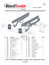
Item Part # Description................................Qty
A1 58486 Air spring ............................................. 2
A2 58571 Air spring .............................................2
B 07028 Right upper bracket.............................1
C 07329 Left upper bracket ...............................1
D 03008 Lower bracket .....................................2
E 10583 3/8” U-bolt ...........................................4
F 17297 M10-1.25 x 45 Bolt .............................. 2
G 17330 M10-1.50 x 45 Bolt .............................. 2
H 18540 M10 Lock washer ................................ 2
I 18435 3/8” Nyloc nut ..................................... 8
J 18444 3/8” Flat washer ..................................8
K 17309 3/8” J-bolt ............................................4
L 18422 3/8” Serrated ange nut ......................4
Item Part # Description................................Qty
M 17124 1/2” Bolt ...............................................2
N 18414 1/2” Flat washer ..................................2
O 18454 3/4” Nylon nut......................................2
P 18450 3/4” Lock washer.................................2
Q 21837 1/4” Elbow ...........................................2
AA 20086sub Air line assembly .................................1
BB 10466 Zip tie ..................................................6
CC 21230 Valve cap ............................................2
DD 18405 5/16” Flat washer ................................2
EE 21234 Rubber washer....................................2
FF 18411 Star washer ......................................... 2
GG 21233 5/16” Hex nut ......................................4
HARDWARE LIST
NOTE
RideControl