
DFD-2S/8
INTRODUCTION
INSTALLATION
STRUCTURAL SECTIONS AND THEIR FUNCTIONS
CIRCUIT DIAGRAM
PRINCIPLES OF OPERATION
CHECKING PROCEDURES FOR TROUBLESHOOTING
ILLUSTRATION AND PARTS LIST
MAINTENANCE AND REGULAR INSPECTIONS
ACCESSORIES
BLADE BREAKAGE DETECTOR
A
B
C
D
E
F
G
J
H

i
920610
DFD-2S/8
CONTENTS
Page
INTRODUCTION
A INSTALLATION
I Installation Environment ................................................................................................ A-1
II Necessaries for Installation ........................................................................................... A-2
III Other Notice ................................................................................................................... A-2
IV Installation Leveling ....................................................................................................... A-2
V Wiring Connection ......................................................................................................... A-4
VI Transportation ................................................................................................................ A-6
B STRUCTURAL SECTIONS AND THEIR FUNCTIONS
I Structures ....................................................................................................................... B-1
II Functions ........................................................................................................................ B-2
1 X-axis Section .......................................................................................................... B-2
2 Y-axis Section .......................................................................................................... B-3
3 Z-axis Section .......................................................................................................... B-4
4 θ-axis Section ......................................................................................................... B-6
5 Spinner Section ....................................................................................................... B-9
6 Elevator Section ...................................................................................................... B-10
7 Transfer Section ...................................................................................................... B-12
8 Microscope Section ................................................................................................. B-13
9 Main Body Section ................................................................................................. B-18
10 Electrical System...................................................................................................... B-20
(1) Construction ........................................................................................................ B-20
(2) Power Supply Section ........................................................................................ B-24
(3) Main Control Section ......................................................................................... B-32
(4) Sub-control Section ............................................................................................. B-53
(5) Attachment Section ............................................................................................ B-62

ii
920610
DFD-2S/8
C CIRCUIT DIAGRAM
Block Diagram 1 (Main) (for DFD-2S/8) ............................................................................ C-1
Block Diagram 1 (Main) (for DFD-2D/8) ........................................................................... C-1A
Block Diagram 2 (Main) ....................................................................................................... C-2
Block Diagram 3 (Main & Sub) (for DFD-2S/8) ................................................................ C-3
Block Diagram 3 (Main & Sub) (for DFD-2D/8) ............................................................... C-3A
Main AC Power Circuit (for DFD-2S/8) ............................................................................. C-4
Main AC Power Circuit (for DFD-2D/8) ............................................................................. C-4A
Main Box AC Power Source ................................................................................................. C-5
Main Box DC Power Source ................................................................................................. C-6
Sub Control Power Circuit (for DFD-2S/8) ........................................................................ C-7
Sub Control Power Circuit (for DFD-2D/8) ....................................................................... C-7A
Main Control Signal Diagram ............................................................................................. C-8
Sub Control Box Wiring Diagram (Y-axis AC Servo) ...................................................... C-9
Sub Control Box Wiring Diagram (Y-axis Pulse Motor) (for DFD-2S/8) ...................... C-10
Sub Control Box Wiring Diagram (Y-axis Pulse Motor) (for DFD-2D/8) ..................... C-10A
ALU Block Diagram .............................................................................................................. C-11
Hard Disk Wiring Diagram ................................................................................................. C-12
Floppy Disk Wiring Diagram .............................................................................................. C-13
Main-Sub/ALU (S I O) Wiring Diagram ............................................................................ C-14
SI/O Wiring Diagram ............................................................................................................ C-15
MCN1 Wiring Diagram (for DFD-2S/8) ............................................................................. C-16
MCN1 Wiring Diagram (for DFD-2D/8) ............................................................................ C-16A
MCN2 Wiring Diagram (for DFD-2S/8) ............................................................................. C-17
MCN2 Wiring Diagram (for DFD-2D/8) ............................................................................ C-17A
MCN3 Wiring Diagram (for DFD-2S/8) ............................................................................. C-18
MCN3 Wiring Diagram (for DFD-2D/8) ............................................................................ C-18A
MCN4 Wiring Diagram (for DFD-2S/8) ............................................................................. C-19
MCN4 Wiring Diagram (for DFD-2D/8) ............................................................................ C-19A
MCN5 Wiring Diagram ........................................................................................................ C-20
MCN6 Wiring Diagram (for DFD-2S/8) ............................................................................. C-21
MCN6 Wiring Diagram (for DFD-2D/8) ............................................................................ C-21A
MCN7 Wiring Diagram ........................................................................................................ C-22
MCN9 Wiring Diagram ........................................................................................................ C-23

iii
920610
DFD-2S/8
CNS Wiring Diagram ............................................................................................................ C-24
Camera & TV Monitor Wiring Diagram (for DFD-2S/8) ................................................ C-25
Camera & TV Monitor Wiring Diagram (for DFD-2D/8) ................................................ C-25A
SCN1 Wiring Diagram (for DFD-2S/8) .............................................................................. C-26
SCN1 Wiring Diagram (for DFD-2D/8) .............................................................................. C-26A
SCN2 Wiring Diagram (for DFD-2S/8) .............................................................................. C-27
SCN2 Wiring Diagram (for DFD-2D/8) .............................................................................. C-27A
SCN4 Wiring Diagram .......................................................................................................... C-28
SCN5 Wiring Diagram .......................................................................................................... C-29
SCN6 Wiring Diagram (for DFD-2S/8) .............................................................................. C-30
SCN6 Wiring Diagram (for DFD-2D/8) .............................................................................. C-30A
SCN7 Wiring Diagram .......................................................................................................... C-31
Outside Relay P.C.B. Circuit Diagram ............................................................................... C-32
Set Up P.C.B. Circuit Diagram ............................................................................................ C-33
PCB (Axis) ............................................................................................................................... C-34
Signal Tower I/F P.C.B. Circuit Diagram .......................................................................... C-35
Spinner Control P.C.B. Circuit Diagram ............................................................... ........... C-36
Spinner Circuit Diagram .......................................................................................... ........... C-37
D PRINCIPLES OF OPERATION
I Linear Scale .................................................................................................................. D-1
1. Main Components .................................................................................................... D-2
2. Block Diagram .......................................................................................................... D-3
3. Principles ................................................................................................................... D-4
4. Scale Specifications .................................................................................................. D-5
E TROUBLESHOOTING GUIDE
I Spinner Pump Problems and Remedies ................................................................... E-1
II Feedback Unit Problems and Remedies ................................................................... E-4
III Checking Procedures for Troubleshooting of Electrical System ............................. E-6
(1) POWER ................................................................................................................ E-6
(2) Servomotor/driver ............................................................................................... E-8
(3) PM motor/driver ................................................................................................. E-10
IV Error Code .................................................................................................................... E-12

iv
920610
DFD-2S/8
1. General ......................................................................................................................... E-12
2. Error Code Tables ...................................................................................................... E-12
3. Details of Error Code ................................................................................................. E-24
F ILLUSTRATION AND PARTS LIST
EXPLODED VIEW OF MAIN BODY (A) .............................................................. F-1
EXPLODED VIEW OF MAIN BODY (B) .............................................................. F-2
EXPLODED VIEW OF MAIN BODY (C) .............................................................. F-3
EXPLODED VIEW OF MAIN BODY (D) .............................................................. F-4
EXPLODED VIEW OF MAIN BODY (E) .............................................................. F-5
EXPLODED VIEW OF MAIN BODY (F) .............................................................. F-6
EXPLODED VIEW OF X-AXIS (A) ........................................................................ F-7
EXPLODED VIEW OF X-AXIS (B).......................................................................... F-8
(Not Assigned) ........................................................................................................................ F-9
EXPLODED VIEW OF Y-AXIS (A) ......................................................................... F-10
EXPLODED VIEW OF Y-AXIS (B) ......................................................................... F-11
EXPLODED VIEW OF Y-AXIS (C) ......................................................................... F-12
EXPLODED VIEW OF Y-AXIS (D) ........................................................................ F-13
EXPLODED VIEW OF y-AXIS (A) (DFD-2D/8 ONLY) ........................................ F-13A
EXPLODED VIEW OF y-AXIS (B) (DFD-2D/8 ONLY) ........................................ F-13B
EXPLODED VIEW OF Z-AXIS (A) (DFD-2S/8 ONLY) ........................................ F-14
EXPLODED VIEW OF Z-AXIS (B) (DFD-2S/8 ONLY) ........................................ F-14A
EXPLODED VIEW OF Z-AXIS (C) (DFD-2S/8 ONLY) ........................................ F-14B
EXPLODED VIEW OF Z-AXIS (D) (BLADE BREAKAGE DETECTOR)
(DFD
-2S/8 ONLY) (OPTION) .................................................................................... F-14C
EXPLODED VIEW OF Z-AXIS (E) (DFD-2D/8 ONLY) ........................................ F-15
EXPLODED VIEW OF Z-AXIS (F) (DFD-2D/8 ONLY) ........................................ F-15A
EXPLODED VIEW OF Z-AXIS (G) (DFD-2D/8 ONLY) ....................................... F-15B
EXPLODED VIEW OF Z-AXIS (H) (DFD-2D/8 ONLY) ....................................... F-15C
EXPLODED VIEW OF MICROSCOPE ................................................................. F-16
EXPLODED VIEW OF θ-AXIS (A) ....................................................................... F-17
EXPLODED VIEW OF θ-AXIS (B) ....................................................................... F-18
EXPLODED VIEW OF LOADING/UNLOADING (A) ......................................... F-19
EXPLODED VIEW OF LOADING/UNLOADIING (B) ....................................... F-20

v
920610
DFD-2S/8
EXPLODED VIEW OF LOADING/UNLOADIING (C) ....................................... F-21
EXPLODED VIEW OF TRANSFER (A) ................................................................ F-22
EXPLODED VIEW OF TRANSFER (B) ................................................................ F-23
EXPLODED VIEW OF TRANSFER (C) ................................................................ F-24
EXPLODED VIEW OF TRANSFER (D) ................................................................ F-25
EXPLODED VIEW OF TRANSFER (E) ................................................................ F-26
EXPLODED VIEW OF TRANSFER (F) ................................................................. F-27
EXPLODED VIEW OF SPINNER (A) .................................................................... F-28
EXPLODED VIEW OF SPINNER (B) .................................................................... F-29
EXPLODED VIEW OF SPINNER (C) .................................................................... F-30
EXPLODED VIEW OF PNEUMATIC PIPING (A) .............................................. F-31
EXPLODED VIEW OF PNEUMATIC PIPING (B) .............................................. F-31A
EXPLODED VIEW OF PNEUMATIC PIPING (C) .............................................. F-32
EXPLODED VIEW OF PNEUMATIC PIPING (D) .............................................. F-33
EXPLODED VIEW OF PNEUMATIC PIPING (E) .............................................. F-34
EXPLODED VIEW OF PNEUMATIC PIPING (F) .............................................. F-35
EXPLODED VIEW OF PNEUMATIC PIPING (G) .............................................. F-36
EXPLODED VIEW OF PNEUMATIC PIPING (H) .............................................. F-37
EXPLODED VIEW OF WATER PIPING (A) ......................................................... F-38
EXPLODED VIEW OF WATER PIPING (B) (DFD-2S/8 ONLY) ........................ F-39
EXPLODED VIEW OF WATER PIPING (C) (DFD-2D/8 ONLY) ....................... F-39A
EXPLODED VIEW OF WATER PIPING (D) ........................................................ F-40
EXPLODED VIEW OF WATER PIPING (E) (DFD-2S/8 ONLY) ........................ F-41
EXPLODED VIEW OF WATER PIPING (F) (DFD-2D/8 ONLY) ........................ F-41A
EXPLODED VIEW OF N2 PIPING (A) .................................................................. F-42
EXPLODED VIEW OF N2 PIPING (B) .................................................................. F-42A
EXPLODED VIEW OF N2 PIPING (C) .................................................................. F-43
EXPLODED VIEW OF N2 PIPING (D) .................................................................. F-44
EXPLODED VIEW OF N2 PIPING (E) .................................................................. F-45
INDEX

vi
920610
DFD-2S/8
G MAINTENANCE AND REGULAR INSPECTIONS
I Maintenance ................................................................................................................. G-1
1 Cleaning ................................................................................................................... G-1
2 Consumables Replacement .................................................................................. G-2
II Regular Inspections ..................................................................................................... G-18
Daily Inspection .................................................................................................. G-18
Weekly Inspection .............................................................................................. G-19
Semiannual Inspection ...................................................................................... G-20
H ACCESSORIES
1 Tape Frames ............................................................................................................ H-1
2 Cassettes .................................................................................................................. H-3
3 Chuck Tables ........................................................................................................... H-3
4 Type MR Flange Set .............................................................................................. H-4
J BLADE BREAKAGE DETECTOR (OPTIONAL)
I Construction ................................................................................................................. J-1
1 Components .................................................................................................................J-1
II Installation ..................................................................................................................... J-4
1 Detection Unit Mounting Position (Component ⑤ in Section I) .................. J-4
2 Photo-amplifier Mounting Position (Component ④ in Section I) ................ J-4
III Fiber Installation ........................................................................................................... J-5
IV Connection ................................................................................................................... J-8
V Operating Procedures ................................................................................................. J-9
1 Preparation for Power ON .................................................................................. J-9
2 Power ON ................................................................................................................. J-9
3 Adjustment .............................................................................................................. J-9
4 Idling ......................................................................................................................... J-10
5 Breakage Detection Function Activation and Reset ........................................ J-11
6 Total Loss Detection Function Activation and Reset ....................................... J-11
7 DIP Switch Setup ................................................................................................... J-12
8 Rotary Switch Setup .............................................................................................. J-13
VI Precautionary Concerns ............................................................................................. J-14
VII Maintenance ................................................................................................................. J-14

INTRODUCTION
DFD-2S/8

910228
INTRODUCTION
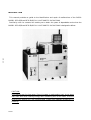
This manual provides an guide to the identification and repair of malfunctions of the DISCO
MODEL DFD-2S/8 and DFD-2D/8 FULLY AUTOMATIC DICING SAW.
Familiarity with its contents will enable you to obtain the years of dependable service that the
MODEL DFD-2S/8 and DFD-2D/8 FULLY AUTOMATIC DICING SAW is designed to deliver.
CAUTION:
This manual uses lint free paper. Since this paper is weakened by heat, do not place
near heat. Also when rubbing strongly with something such as an eraser, since the
printing will become thin and contaminated. Please take adequate precautions in
handling.
DFD-2S/8

A INSTALLATION
DFD-2S/8
A

A-1
910228
DFD-2S/8
A. INSTALLATION
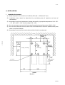
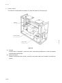
I Installation Environment
(1) Required space for this machine is 1,420mm (56″) (W)×1,100mm (43″) (D).
(2) Installation place should be determined by considering ease of operation and ease of
maintenance.
(3) Keep away from where temperature changes abnormally. Appropriate temperature is 20~25℃
±1℃ (68~69.5°F±1.8°F) and humidity is 55±15%.
(4) Do not use a power source which flucturates frequently. Appropriate power is 200V±10%.
(5) Do not use a power source which emits noise. Permitted noise is less than 2,000V and its pulse
width is less than 500n/sec.
(6) Keep away from where the shock and/or sensible vibration are observed.
Fig. A
-
--
-
1
Wall
Jack sheet
Space
need
electronics
drawer
(Loading, Unloading) (Main body)

A-2
910228
DFD-2S/8
II Necessaries for Installation
(1) Power supply cord
(2) Piping hose
A hose provided as a standard accessory is 2m (79″) long. If you need a longer one, please tell
us previously. When you use other hoses, select those which have sufficient durability against
the proper fluids.
(3) Precision level
A small sized one.
(4) Tools
Supplied with the machine.
III Other Notice
(1) Install where floor has enough strength.
(2) Install where air, water, drain pipes, and power etc. can be supplied nearby.
(3) Connect piping hoses after cleaning their inside.
(4) Use dry air that’s filter is 0.003PPMWT/wt and its dew point is below than -15℃ (5°F).
(5) Be sure to ground the machine.
(6) During installation do not load shock and /or use excessive force against the machine.
(7) After installation, remove all the hanging fittings and metal fittings for fixing.
(8) After installation, check that all the wiring terminals and piping joints are connected safely.
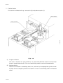
IV Installation leveling
Level the machine using the jack provided within the machine.
(1) Patch a jack sheet under the six jack bolts. Raise up equally until all casters are above the
floor.
(2) Place a level on a chucktable.
(3) Adjust level for four directions (before and behind, left and right) by turns shifting the jack
bolt.
(4) Set the level within 1 scale (0.02mm/1m)(0.0008″/39″) for all four directions.
(5) Check and confirm that all the jack bolts touch the jack sheet.

A-3
910228
DFD-2S/8
Illustration Of Installed Bearing
Fig. A
-
--
-
2
Fig. A
-
--
-
3
Jack bolt
Jack
sheet
Caster
Chuck table Level
90mm
(3.5")

A-4
910228
DFD-2S/8
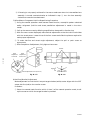
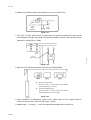
V Wiring Connection
(1) The following illustration shows the piping points and junction points at the rear of the
machine.
(2) Please verify the coupling connections.
(3) Be sure to connect the power source cord.
(4) The power source cord for the monitor is to be connected to a 100V table tap within the
machine through the cover.
(5) Signal cables for the monitor and for the signal lamp are to be linked to each connecter by the
cords leading from the machine.

A-5
910228
DFD-2S/8
Fig. A
-
--
-
4
NO Name Remarks NO Name Remarks
1 Main drain Duct hose 50
MSTDH50T 8 Cooling water out Blade hose ID15
MSTBH22X15C
2 Main duct Duct hose 100
MSTDH100T 9 Exhaust drainage
(chuck table) Blade hose ID12
MSTBH18X12C
3 Spinner duct Duct hose 100
MSTDH100T 10 DI water Blade hose ID15
MSTBH22X15C
4 Spindle exhaust Junron tube8×5 11 N2 Blade hose ID15
MSTBH22X15C
5 Cooling water in Blade hose ID15
MSTBH22X15C 12 Rinse Blade hose ID15
MSTBH22X15C
6 Water for cutting Blade hose ID15
MSTBH22X15C 13 Spinner drainage Blade hose ID32
MSTBH41X32C
7 Air Blade hose ID15
MSTBH22X15C 14 Exhaust
drainage (spinner) Blade hose ID32
MSTBH41X32C

A-6
910228
DFD-2S/8
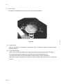
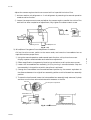
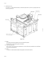
VI Transportation
(1) Take off all piping and wiring.
(2) Draw water out of the machine.
(3) Take off the monitor.
(4) Take off the monitor base, the signal lamp, and the upper cover.
(5) Fix the Y-axis and the Z-axis with proper fittings.
(6) Fix the transfer arm with a thin string.
(7) Put on a hanging fittings for transportation.
(8) Run a pole through the hanging fitting and raise the machine with a crane.
(9) Notes for craning:
●Pay attention that ropes, etc. do not touch the machine.
●Do not shock the machine.
●Do not incline the machine excessively.
●Do not weigh on the cover.
(10) After raising up the machine, all the jack bolts are to be pulled in to the utmost. If they
remain below the casters, it is possible to break them when the machine is placed on the
ground the next time.

A-7
910228
DFD-2S/8
Illustration Of Transport Method
Fig. A
-
--
-
5

B STRUCTURAL SECTIONS AND THEIR FUNCTIONS B
DFD-2S/8

B-
--
-1
910228
DFD-2S/8
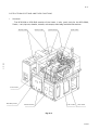
B. STRUCTURAL SECTIONS AND THEIR FUNCTIONS
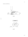
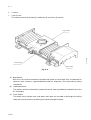
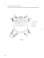
I. Structures
The DFD-2S/8 or DFD-2D/8 consists of the X-axis, Y-axis, y-axis (only for the DFD-2D/8),
Z-axis,θ-axis, spinner, elevator, transfer, microscope, main body, and electrical sections.
Elevator section Spinner section Transfer section Z-axis section
Fig. B
-
--
-
1
θ-axis section
Main body section Electrical section X-axis section Y-axis section

B-2
910228
DFD-2S/8
II. Functions
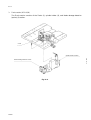
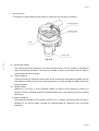
1. X-axis Section
This section consists of the base (1), leadscrew (2), and cover (3) sections.
Fig. B
-
--
-
2
(1) Base Section
With theθ-axis section mounted on the table that slides on the straight rails, the base section
performs work transport, rightward/leftward feed for alignment, and reciprocating cutting
movements.
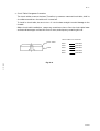
(2) Leadscrew Section
This section moves the slide table by means of the ball -bearing leadscrew coupled direct to the
AC servomotor.
(3) Cover Section
The splash cover, bellows cover, and water drain duct are provided to discharge the cutting
water out from the machine, protecting the mechanism against water.
Cover section
Screw section
Base section
Page is loading ...
Page is loading ...
Page is loading ...
Page is loading ...
Page is loading ...
Page is loading ...
Page is loading ...
Page is loading ...
Page is loading ...
Page is loading ...
Page is loading ...
Page is loading ...
Page is loading ...
Page is loading ...
Page is loading ...
Page is loading ...
Page is loading ...
Page is loading ...
Page is loading ...
Page is loading ...
-
 1
1
-
 2
2
-
 3
3
-
 4
4
-
 5
5
-
 6
6
-
 7
7
-
 8
8
-
 9
9
-
 10
10
-
 11
11
-
 12
12
-
 13
13
-
 14
14
-
 15
15
-
 16
16
-
 17
17
-
 18
18
-
 19
19
-
 20
20
-
 21
21
-
 22
22
-
 23
23
-
 24
24
-
 25
25
-
 26
26
-
 27
27
-
 28
28
-
 29
29
-
 30
30
-
 31
31
-
 32
32
-
 33
33
-
 34
34
-
 35
35
-
 36
36
-
 37
37
-
 38
38
-
 39
39
-
 40
40


DISCO DFD-2S/8 User manual
- Type
- User manual
- This manual is also suitable for
Ask a question and I''ll find the answer in the document
Finding information in a document is now easier with AI
Other documents
-
Fagor CNC 8058elite M User manual
-
Omega PHP-800 Series Owner's manual
-
Fagor CNC 8070 for other applications User manual
-
Fagor Laser 8060 CNC User manual
-
Greenheck 463543 Field Supplied Sleeves on Fire Smoke Dampers Operating instructions
-
Greenheck Fan DFD-M210 User manual
-
-
Keysight U8903B User manual
-
-