TUXEDO Distributors TC-950 Tire Changer Installation guide

Type
Installation guide
TC-950 & TC-950-WPA
July 2017
TC-950 & TC-950-WPA
2
TC-950 & TC-950-WPA
July 2017
WARNING
This instruction manual is the important part of the product. Please read it carefully and keep it properly in order
to use it when maintain and examine the machine.
This machine is only applied to mount, demount and inflate the tire in the specified scope and not for any other
purpose.
The manufacturer will not be responsible for the damage or injury caused for the operation not properly and out
of the range.
NOTE: This machine should be operated by the special trained qualified personnel. When operating, the
unauthorized person will be kept far away from the machine.
Please note the safety label stuck on the machine.
Operators should wear safety protective facilities such as working suit, protective glasses, and earplug and
safety shoes. Keep your hands and body from the movable parts as possible as you can. Necklace, bracelet
and loosen clothing may cause dangerous to the operators.
Tire changer should be installed and fixed on the flat and solid floor. The more than 0.5m of distance from the
rear and lateral side of the machine to the wall can guarantee the perfect air flow and enough operation space.
Do not place the machine in the site of high temperature, high humidity, and dust and with flammable and
corrosion gas.
Without the permission from the manufacturer, any change on the machine parts will cause injury/damage to the
machine/operator.
Pay attention that the tire changer should be operated under the specified voltage and air pressure.
If you want to move the tire changer, you should under the guidance of the professional service personnel.
3
TC-950 & TC-950-WPA
July 2017
SAFETY LABEL INSTRUCTIONS
Electrical Shock
Do not place any part of your body under
the demount tool.
When breaking tire bead, the bead
breaking blade will quickly move to the left.
Note: When pressing the tire to the rim, the
opened clamp cylinder may cause injury to the
hand of the operator. Ensure not touch the
sidewall of the tire during pressing operation.
When clamping the rim, do not place hand or
other parts of the body in between the clamp &
the rim.
CAUTION LABELS
4
TC-950 & TC-950-WPA
July 2017
SAFETY LABEL POSITION DIAGRAM
Pay attention to keep the safety labels complete. When it is not clear of missing, you should change the new
label(s).
Operators should always note the safety labels to clearly understand the meaning of each label.
5
TC-950 & TC-950-WPA
July 2017
CONTENTS
CHAPTER 1 - BRIEF INTRODUCTION
1.1 INTRODUCTION
1.2 TECHNICAL PARAMETER
1.3 APPLICATION SCOPE
1.4 ENVIRONMENT REQUIREMENT
CHAPTER 2 - CONFIGURATION AND OPERATION
CHAPTER 3 - INSTALLATION AND CALIBRATION
3.1 OPEN PACKAGE CARTON
3.2 INSTALLATION OF THE COLUMN
3.3 AIR SOURCE INSTALLATION
CHAPTER 4 - DEMOUNT AND MOUNT TIRE
4.1 DEMOUNT TIRE
4.2 MOUNT TIRE
4.3 INFLATION
4.4 RAPID INFLATION
CHAPTER 5 - MAINTANENCE AND REPAIR
CHAPTER 6 - INSTALLATION & OPERATION OF THE ASSISTANT ARM (OPTIONAL)
6.1 LEFT ASSISTANT INSTALLATION
6.2 RIGHT ASSISTANT INSTALLATION
CHAPTER 7 - TRANSPORTATION
CHAPTER 8 - ELECTRICAL AND PNEUMATIC DRAWINGS
CHAPTER 9 - GENERAL TROUBLESHOOTING
ADDITIONAL INFORMATION: MACHINE OIL SAFETY DATA SHEET
LIMITED WARRANTY
6
TC-950 & TC-950-WPA
July 2017
CHAPTER 1 - BRIEF INTRODUCTION
1.1 BRIEF INTRODUCTION
This series of equipment is the tire changer with fixed column and rocker arm tire changer. It is suitable to
mount, demount and inflate all types of motorcycle tire with tube & tubeless. The operation is easy,
convenient, safety and reliable. It is the necessary equipment for the auto service shop and tire shop.
1.2 TECHNICAL PARAMETER
· Operation Pressure: 8-10 bar (115 - 145 PSI)
· Motor: 110VAC-1PH, 60Hz
· Turntable Speed: 6 RPM
· Noise Level: 70dBA
1.3 APPLICATION SCOPE
Model
#
Max. Wheel
Diameter
Max. Wheel
Width
Rim Diameter
(Outer Clamping)
Rim Diameter
(Inner Clamp)
TC-950 1250mm (47) 400mm (15.74) 12 - 23 10 - 20
1.4 ENVIRONMENT REQUIREMENT
· Ambient temperature 045 (32F - 113F)
· Relative humidity 3095%
Without dust and flammable / explosive gases
· The operation space around the machine will not smaller than the indicated in Fig.1
Fig. 1
If the tire changer is installed outdoors, you must have a protective type shed or cover to protect from
rain and sun. It is prohibited to use near flammable gases
(
2
8
)
(20)
(
20
)
7
TC-950 & TC-950-WPA
July 2017
Fig. 2
Fig. 3
CHAPTER 2 - CONFIGURATION AND OPERATION
1. Vertical Shaft Spring
2. Lock Handle
3. Hexagon Shaft
4. Demount Head
5. Claw
6. Turntable
7. Operation Label
8. Turntable Pedal
9. Clamp Pedal
10. Bead Breaker Pedal
11. Limit Handle
12. Lock Handle
13. Column
14. Inflation Nozzle
15. Clamp Cylinder
16. Blade Handle
17. Air Filter, Regulator & Lubrication Unit
18. Bead Breaking Cylinder
19. Bead Breaker Arm
20. Bead Breaking Blade
21. Crowbar Tire Tool
22. Air Tank
23. Inflation Gauge Box
8
TC-950 & TC-950-WPA
July 2017
CHAPTER 3 - INSTALLATION AND CALIBRATION
Before installation, carefully read the manual. Any unauthorized modifications and/or changes to any parts
and/or components of the tire machine, may cause damage to the machine.
Installation and assembly personnel should have the specific electrical knowledge.
Operators must be trained and authorized to operate the machine.
Before installation, carefully read the equipment list. If there are any questions, please contact the dealer or
representative.
To ensure the success of the installation, please have the following common tools:
Adjustable Wrenches, Socket Wrenches, Hex Keys, Pliers, Screw Driver & Hammer & multi-purpose Meter.
3.1 UNPACKING
3.1.1 According to the de-package instructions on the package box, detach the box and remove the
package material to check for machine damage and if all spare parts are included.
3.1.2 Keep the package material far away from the working site and dispose of properly.
3.2 INSTALLATION
3.2.1 After un-packaging the package carton, take out Accessory Boxes (Fig. 4-1), Bead Breaking Arm
(Fig 4-5) and Column Assembly (Fig. 4-2). Ensure to position the machine according to the information
noted in Chapter 1.4.ENVIRONMENT REQUIREMENT. Remove mounting bolts, lock washers & flat
washers from Column Base (Fig. 4-4) in preparation to install Column to Base (Fig. 5).
3.2.2 Place the Column on Base with the direction of the warning label facing forward. Align the Column
holes to the Base holes and mount with bolts, lock washers & flat washers, noted in the previous
Chapter.
3.2.1 Using a Torque Wrench, tighten bolts to 52 ft.-lbs. (Fig. 5.) to secure Column to Base.
Fig. 4 Fig. 5
9
TC-950 & TC-950-WPA
July 2017
3.2.3 Use the wrench to remove the screw (Fig 6-3) Hexangular Shaft (Fig. 6-1) and take off the vertical
Shaft Cap (Fig. 6-2).
When removing the screw on the vertical shaft cap, youll need use the lock handle to lock the
hexangular shaft to avoid sliding off to damage the machine or cause injury to personnel!
Install the vertical Shaft Spring (Fig. 7-1) on the vertical shaft. Mount the vertical shaft cap and mount the
removed screw and assemble the hand wheel into the nut bushing of the rocker arm (Fig. 7-2).
3.2.4 Remove the Lock nut at the front end of the bead breaking / cylinder piston rod (Fig. 8-1) and use
the wrench to remove the nut on the bead breaking arm bolt (Fig. 8-4). Remove the bolt (Fig. 8-3) and
hang the spring (Fig. 8-2).
3.2.5 Position the bead breaking Arm Shaft Bushing into the bead breaking Support Plate on the body
(Fig. 9-1) to align the hole and install the bead breaking bolt (Fig. 9-2) and assemble the nut to lock (Fig.
8-4). Insert the piston rod (Fig.10-2) through the hole of the bead breaking slide bushing (Fig. 10-1). The
surface of the slide bushing should be facing outwards (Fig. 10). Assemble the removed nut (Fig. 8-1)
into the front end of the piston rod. The distance from the edge of the bead breaking blade to the bead
breakers rubber pad is 1-3/16 to 1-1/2 (30-40mm) as shown in Fig.11. Install the return spring (Fig. 9-3)
Note: If the machine is the one with the quick inflation feature; please open the side panel and insert 2 pieces
of Ø12 hose to the inlet of the quick inflation valve and to the Ø12 nozzle. Reinstall the side panel.
Fig
Fig. 7
Fig. 8
Fig. 9
Fig. 10
10
TC-950 & TC-950-WPA
July 2017
3.2.6 If being equipped with the tool box, you must fix firmly and the column completely installed.
3.3 AFRL - AIR FILTER, REGULATOR & LUBRICATOR INSTALLATION:
Note: The AFRL has been detached and placed in the accessory box. The AFRL assembly will be installed
at the customers location during installation. This is done to prevent damages during shipment.
3.3.1 Remove the AFRL and mounting screw from the accessory box. Remove any oil or dust. Use the
screw to mount the AFRL to the right side of the body (Fig. 12).
3.3.2 To connect air hose: Detach the adapter on the ø8 hose on the side wall of the body and insert it
into the elbow fitting (Figs.13 &14). The adapter is to keep the hose from sliding into the body.
3.3.3 To connect the inflation gun or inflation gauge box: Inlay the adapter of the inflation gun or inflation
gauge box into the groove (Fig. 15) on the open nut of the air regulator fitting. Tighten nut to connect the
air regulator.
Fig. 11
Fig. 12
Fig. 13
Fig. 14
Fig. 15
11
TC-950 & TC-950-WPA
July 2017
3.3.4 The AFRL has been pre-adjusted at the factory. If it needs adjusted: Pressure: Lift up on the
pressure adjustable knob (Fig. 16-1) and turn clockwise to increase air pressure. Meanwhile, if turned
counter-clockwise, the air pressure will decrease. Oil Feed: Use a screw driver to turn the screw to
adjust flow rate (Fig. 16-2). If turned clockwise, the oil flow speed will be reduced. If turned
counter-clockwise, the oil flow will be increased.
CHAPTER 4 - DEMOUNT AND MOUNT TIRE
4.1 DEMOUNT TIRE
4.1.1 Deflate the tire completely by pulling out the valve stem and/or core. Use a special tool (Wheel
Balancer Hammer) to remove balance weights from the rim (Fig. 17).
4.1.2 Place the tire between the bead breaking blade and rubber contact pad (Fig. 18). Then step down
on the Bead Breaker Pedal (Figs. 2-10 or 3-10) to detach the rim from the tire. Repeat the same
operation on the other sections of the tire to fully detach from the rim. Place the wheel with the tire
detached from the rim on the turntable and step on the Clamp Pedal (Figs. 2-9 or 3-9) to clamp the rim.
Note: You can select either the outer clamping or inner clamping to properly clamp the wheel according
to different rim types.
Fig. 16
Fig. 17
Fig. 18
12
TC-950 & TC-950-WPA
July 2017
To detach the lip smoothly, you can use the brush to spread the lubricant or thick soap liquid between
the lip and rim.
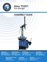
4.1.3 Position the Hexangular Shaft (Fig 2-3) to the working position to situate the demount tool to be
close to the rim of the wheel, along with using the Limit Handle knob (Fig. 3-11) to position and secure
Hex Shaft to rim. Once properly positioned, secure using the Lock Handle (Fig. 2-12).
Note: The demount tool will automatically provide a small 2mm gap to the rim (Fig. 19).
The angle of the demount tool has been calibrated according to the standard rim of 13". If handling
the extra-big or extra-small rim, you can reposition.
4.1.4 Use the included Crowbar Tire Tool to detach tire from rim as shown in Fig 20, using the Hex Shaft
as a pivot point. Once the Crowbar is positioned, then step on the Turntable Pedal (Fig. 2-8) to rotate the
turntable clockwise until the entire tire lip is completely detached from rim.
Note: If handling a tubed tire, try to avoid the damage to the tube, as the operator should keep the valve
stem 4 (10cm) from the right side of the demount tool when demounting tires.
If the demounting of the tire gets jammed, please stop the machine immediately and then lift up the
pedal to let the turntable rotate counterclockwise to remove the resistance!
4.1.5 When handling the tubed tire, Take out the tube and then move the lower lip upwards to the upper
edge of the rim and then repeat the above steps to detach the other lip.
In the process of demounting tire, you should keep your hands and the other parts of your body from
the movable parts. Any necklaces, bracelets and/or loose clothing can cause injury to personnel!
4.2 MOUNT TIRE:
Before mounting a tire, ensure to check if the tire and rim are of the same dimension!
Fig. 19
Fig. 20
13
TC-950 & TC-950-WPA
July 2017
4.2.1 Clean the dirt and rust from the rim and position on the turntable. Secure rim to turntable using the
clamps.
4.2.2 Spread the lubrication liquid or soap liquid around the lip of tire. Tilt the tire against the rim, keeping
the front end upwards. Press down on the hexangular shaft to move the demount tool arm to contact with
the rim and lock. The left lip above the tail of the demount tool and the right lip will be positioned under
the front end of the demount tool (Fig. 21). Then rotate the turntable clockwise to guide the bottom lip into
the tire detaching slot.
4.2.3 If there is tube, place it in the tire and plug the core and assemble the lip according to the above
mentioned step (Fig. 22).
4.3 INFLATION:
When inflating the tire, please be careful and follow the operational process. Ensure to check the air routing
to see if the air connection is ok. Note: the tire changer is equipped with an inflation pressure gauge to
monitoring the inflation of the tire and the tires pressure (Fig. 23).
Fig. 21
Fig. 23
Fig. 22
14
TC-950 & TC-950-WPA
July 2017
1. Loosen the tire from the turntable.
2. Connect the inflation hose with the tires preinstalled valve stem (Fig. 23)
3. In the process of inflation, you should stop the inflation periodically to confirm the pressure indicated on
the pressure gauge so not to exceed the tires pressure as specified by the manufacturer. The pressure
decrease valve equipped in the machine will make the air pressure to not exceed 3.5bar or 51psi. The
customer can obtain different inflation pressures by adjusting the regulators pressure according to the
requirement.
4. If the inflation pressures too high, you can press down on the deflation button on the inflation device to
reach the required air pressure.
4.4 Rapid Inflation
If the tubeless tire does not fit securely to the rim, you can first apply rapid inflation by using the bead
seating Inflation Jets integrated into the clamps and then use common inflation method:
1. Clamp the wheel and connect the inflation hose.
2. Step down the Inflation Pedal to the lowest position (2) and quickly release the pedal when the tire is
full to the upper position (1) as shown above in Fig 24.
3. Repeat stepping on the Inflation Pedal multiple times to confirm the pressure indicated on the
pressure gauge does not exceeds the pressure specified by the manufacturer.
During this process, you should always ensure the wheel has been tightly clamped!
Explosive Warning!
When inflating, please follow the following instructions:
o Carefully check that the tire and the rim are of the same dimension.
o Check the wear condition of the tire to confirm the tire isnt damaged before inflation!
When inflating the tire, please be carefully. Keep your hands and body away from the tire.
Fig. 24
15
TC-950 & TC-950-WPA
July 2017
CHAPTER 5 - MAINTANENCE & REPAIR
Only a qualified technician can execute the maintenance on the tire changer. Before any
maintenance is performed, shut off power. Meanwhile, shut off the air supply and push the air supply
switch to the off position and completely deflate the residual air in the machine. To correctly use the
tire changer and prolong its working life, it is necessary to periodically provide maintenance and
repairs according to the instruction manual. If maintenance and/or repairs are not made, there is a
possibility the operation and reliability of the machine may be affected, along with possible injury to
operator.
Monthly Maintenance:
· Keep tire changer and working area clean.
· Clean hexangular shaft (Fig. 25). Use machine oil to lubricate shaft.
· Clean turntable, clamps and demount head. Use lithium based oil to lubricate (Fig 26).
· Check the oil level on the AFRL. If the oil level is low, add SAE-30 lubrication oil to fill line as
required (Fig 27).
· Check the oil water separator trap and drain water, as required.
· Periodically check and adjust the tension of the drive belt. Properly adjust, by adjusting the nut in A
and B to proper tension (Fig. 28).
· Check all connection parts and tighten as required.
Fig. 25
Fig. 26
Fig. 27
Fig. 28
16
TC-950 & TC-950-WPA
July 2017
Hexangular Shaft & Lock Plate Gap Adjustment:
When pressing downward on the lock handle, the hexangular shaft will easily slide up & down vertically due to
the weight of the hexangular shaft and the return spring. When the lock handle is rotated clockwise about 100
degrees, the cam connected to the handle will push up on the lock plate to lock the hexangular shaft into
position. The gap distance can be increased or decreased by adjusting the adjustment nut (Fig. 29).
Fig. 29
17
TC-950 & TC-950-WPA
July 2017
TC-950-WPA
Left Side Press Arm Assist
Installation and Operation
(Left Side Press Arm Assembly)
18
TC-950 & TC-950-WPA
July 2017
Fig. 30
Fig. 32
-
1
CHAPTER 6 - INSTALLATION & OPERATION - LEFT SIDE PRESS ARM
6.1 INSTALLATION - LEFT SIDE PRESS ARM
6.1.1 The Left Side Press Arm assistant can be equipped on the tire changer which can handle a tire
with the rim diameter of 20 to assist in the operation of demounting stiff and/or low profile tires. The Left
Side Press Arm provides assistance for single operator capability.
Before installation, the power and air supply must be shut off!
6.1.1 The left and right side of the base plate of body of the tire changer can handle a tire with a diameter
of more than 20 all have the installation hole for the left assistant prepared. Before installation, you can
remove the side panel and take off the installation rubber plug. If there is a tool box, you should detach
the tool box and set aside.
6.1.2 Unpack the Side Press Arm package and ensure all parts & components are included according to
the packing list. After confirmation, takeout the base assembly and install using the hex socket screw and
washer (Fig. 30).
6.1.3 Position the platform of the base plate, for the base assembly into the body through base plate on
the left-back side of the body. Align the threaded holes to the reinforced holes on the bodys base and
connect using hex bolts and washers (Fig 31).
6.1.4 Install the body bracket (Fig.32-1) on the base assembly. Align holes and connect to base using the
screws that were removed. Do not fully tighten at this time.
Fig. 31
19
TC-950 & TC-950-WPA
July 2017
Fig. 33
Fig. 34
Fig. 35
Fig. 36
6.1.5 Use the fixed supporting bracket (Fig. 33) to connect the body bracket and the body. Insert the
screw to connect.
6.1.6 Connect the air source hose (Fig. 34-2) using the Y Tee fitting to connect the outlet hose and the
other end to connect with the inlet of the assistant pressure adjusting valve (Fig. 34-1).
6.1.7 According to the (Fig. 35), fit the bracket on the body that secures the tool box on the fixed bracket
and then use the lock nut to tighten.
6.1.8 Loosen the nut below the base and turn the screw clockwise until its against the ground and is tight
(Fig. 36). Re-install the side panel and tool box that was removed section 6.1.1.
The installation of the Left Side Press Arm assembly is now complete.
20
TC-950 & TC-950-WPA
July 2017
Fig. 37
Fig. 38
Fig. 39
Fig. 40
6.2 USING THE LEFT SIDE PRESS ARM
6.2.1 After detaching the tire from the rim according to the instruction of the Chapter 5, you can execute
the following operations.
6.2.2 First, position the claws according to the dimension of the tire and then clamp the rim by the claws
and position the tire press cone roller at the center of the rim (Fig. 37). Push down on the manual valve to
press the rim down until the rim is lower than the surface of the claws. At this moment, you can
immediately lock the rim. Lift up the support arm and place it at the working position and take off the
press cone roller and place it on the support.
6.2.3 Use the press (Fig. 38-1) to press down the tire by sections of the rim that is detached from the tire
and use the brush to spread the lubricant on edge of the lip. Position the demount tool (FIG 40-2) in the
demount position. Place the press beside the demount tool to press down the lip and insert the crowbar
below the demount tool in between the rim and lip (Fig. 39). Then lift up the press and move it to the
position opposite to the demount tool and press the lip into the tire detach groove and then rotate the
crowbar to lift the lip onto the demount tool (Fig. 40). Rotate the turntable to detach the upper lip.
  • Page 1 1
  • Page 2 2
  • Page 3 3
  • Page 4 4
  • Page 5 5
  • Page 6 6
  • Page 7 7
  • Page 8 8
  • Page 9 9
  • Page 10 10
  • Page 11 11
  • Page 12 12
  • Page 13 13
  • Page 14 14
  • Page 15 15
  • Page 16 16
  • Page 17 17
  • Page 18 18
  • Page 19 19
  • Page 20 20
  • Page 21 21
  • Page 22 22
  • Page 23 23
  • Page 24 24
  • Page 25 25
  • Page 26 26

TUXEDO Distributors TC-950 Tire Changer Installation guide

Type
Installation guide

Ask a question and I''ll find the answer in the document

Finding information in a document is now easier with AI