Page is loading ...

INSTALLATION INSTRUCTIONS
THESE INSTRUCTIONS MUST BE
LEFT WITH HOME OWNER
MT246D
2930, 2940 & 2950 SERIES
®
Before turning water on during either rough-in or trim-out, make sure the cartridge retainer nuts are in place. The cartridge and
cartridge retainer nuts were properly installed and tested before leaving the factory. Although it is unlikely, it is nevertheless possible
that through the handling of the faucet by any number of persons the cartridge retainer nuts may not be properly installed. This
should be carefully checked at time of rough-in and trim-out. If the cartridge retainer nuts are not properly installed, water pressure
could force the cartridge out of the faucet body. Personal injury or water damage to the premises could result.
CAUTION:
Always turn water OFF before disassembling the faucet. Open both faucet handles to relieve
water pressure to insure that COMPLETE water shut-off has been accomplished.
WARNING:
Do not solder the threads
or apply heat to the valve.
Serious internal damage
could result.
Pipe, ells and nipples are not
furnished with the valve.
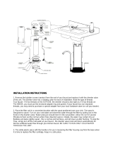
MEASUREMENTS: These are shown in the
drawings. The depth measurement is critical.
The center line of the supply and discharge
piping should be a maximum of 3-1/16" and a
minimum of 2" behind the finished wall sur-
face, including tile. This is 1-1/16" of adjust-
ment. It is suggested that for best appear-
ance of the handles on the finished valve, the
rough-in should be made near the maximum
limit.
LEVER & CROSS TWO-HANDLE
TUB/SHOWER VALVE
SHOWERHEAD, ARM AND FLANGE
(NOT INCLUDED)
FINISHED
WALL LINE
ESCUTCHEON
HANDLE
HUB
DIVERTER
SPOUT
(NOT INCLUDED)
MIN 2"
MAX 3-1/16"
1/2" ELL IRON
PIPE OR TUBING
USE 1/2"
COPPER
TUBING
FOR TUB
DROP
SHOWER
45" - 48"
32" FOR
TUB/SHOWER
COMBINATIONS
AND TUB
ONLY MODELS
FLOOR
LOOKOUT
NIPPLE
6'6"
HANDLE
INSERTS
(NOT INCLUDED)
3/4" MAX
WALL THICKNESS
1-5/8" VALVE
OPENING
IMPORTANT: SEE FLUSHING
INSTRUCTIONS PAGE 2

MT246D
For Connecting Supply Lines:
Solder the supply lines to the valve body supply ports.
CAUTION: Applying excessive heat to the valve body may damage the cartridge.
PLUG
BUTTON
HANDLE
SCREW
HANDLE
HUB
ESCUTCHEON
HANDLE
INSERT
(NOT INCLUDED)
ACRYLIC
HANDLE
INSERT
(NOT INCLUDED)
O-RING
O-RING
HANDLE
INSERT
(NOT INCLUDED)
O-RING
BOLT
Flow Director Instructions:
Flow director is set-up for piping from floor to ceiling. For water supply lines, plumbed
ceiling to floor, please follow these instructions.
1. Use a large flat blade screwdriver and remove the flow director located in the
center port as illustrated.
2. Hold the valve with the supply ports in the up position (pointing toward ceiling). Re-install
the flow director in the center port.
Flushing:
IMPORTANT: Before closing all wall openings, pressure test valve and complete system using
flushing instructions.
IMPORTANT:
Pipe chips, sand, stones and other solids found in new and renovated plumbing can damage the sealing surfaces of the
cartridge and cause a leak. To avoid damage, DO NOT TURN ON SUPPLY VALVES until instructed below:
1. After installing and connecting your new faucet, be sure a tube spout and shower arm are installed, open both hot and
cold cartridges.
2. Turn on both hot and cold water supply valves and allow the water to run from tub spout for 15 seconds.
3. Pull up on the diverter knob on the tub spout and run water through the shower riser for 15 seconds.
4. Turn off the hot and cold cartridges, install the showerhead.
5. Check the system for leaks.
To Install Handle Insert:
Be sure O-ring is in place on insert, as
shown. Thread insert into handle hub.
Insert handle screw and tighten se-
curely. Replace plug button.

Reassembly:
TO INSTALL LEVER & CROSS HANDLES:
Place the handle hubs onto the upper handle adapters, do not install handle screws. Rotate hot handle clockwise and cold
handle counterclockwise until they stop in the OFF position. If it is necessary to adjust handle orientation note handle position.
Remove handle, pull out on the upper handle adapter, replace the handle and turn to the desired position. Push in on handle
to reengage with lower handle adapter. Install the wall tube, escutcheon retainer and escutcheon. Replace handles and install
handle screws and tighten securely, then install plug buttons.
FLOW
DIRECTOR
CENTER
PORT
VALVE
BODY
CARTRIDGE
LOWER
HANDLE
ADAPTER
UPPER
HANDLE
ADAPTER
CARTRIDGE
NUT
STEM
GUIDE
WALL
TUBE
ESCUTCHEON
RETAINER
ESCUTCHEON

MT246D AUG 96
25300 Al Moen Drive, North Olmsted, OH 44070
®
HELPLINE: Call our toll free Helpline number,
(800) BUY-MOEN
(289-6636)
for answers to any product, installation, replacement
parts, or warranty questions.
© Moen Incorporated 1996
Printed in U.S.A
/