Page is loading ...

For additional product information visit our website at http://www.apextoolgroup.com
Instruction Manual
PL92-5001EN
09/02/2015
230Q Series
Inline & Right Angle Adaptive Drills
230QR Series 230QB Series

Page 2
PL92-5001EN
09/02/2015 Quackenbush®
General Information
For this Instruction Manual
This Instruction Manual is the Original Instruction Manual intended for all persons who will operate and maintain
these tools.
This Instruction Manual
• provides important notes for the safe and efcient use of these tools.
• describes the function and operation of the 230Q series tools.
• serves as a reference guide for technical data, service intervals and spare parts ordering.
• provides information on optional equipment.
Identication text:
230Q represents all models of the right angle pnuematic nutrunner as described in this manual
Ú indicates a required action
• indicates a list
<..> indicates a reference number from the exploded parts drawings
Arial indicates an important feature or instruction written in Arial Bold
Identication graphic:
¢ indicates a directional movement
ò indicates a function or force
Copyright protection:
Apex Tool Group, LLC reserves the right to modify, supplement or improve this document or the product without
prior notice. This document may not be reproduced in any way, shape or form, in full or parts thereof, or copied
to another natural or machine readable language or to a data carrier, whether electronic, mechanical, optical or
otherwise without the express permission of Apex Tool Group, LLC.

Page 3
PL92-5001EN
09/02/2015
Quackenbush®
Nomenclature
230 Q X A - 9/3 - XX - X X X - X XXX
Tool Series
230
Brand
Q = Quackenbush
Tool Configuration
B = Inline
R = Right Angle
Adaptive
-- = Not Required
V = Variable RPM
Spindle Speed (RPM)
9/3 = 900 - 300
Feed Rate (select from catalog)
10 = .001
20 = .002
Nose Attachment Thread
A = 2-1/4 - 20
B = 1-9/16 - 20 (Standard)
E = Indexer w/2-1/4 - 20 (add 2.5" to spindle length)
F =
Indexer w/1-9/16 - 20 (add 2.5" to spindle length)
Forward Thrust (Lbs.)
A = 2,400
B = 1,800 (Standard)
C = 1,200
D = 800
E = 600
F = 400
Shear Pin
A = 10 - 51 ft. lbs.
B = 7 - 35 ft. lbs.
C = 4 - 23 ft. lbs.
D = 10 - 62 ft. lbs.
Accessories
A = Nose
B = Spindle
C = Chuck
D = Lubricator
E = Depth Sensing
F = Fluid Inducer
G = None
Last 3 digits of material number

Page 4
PL92-5001EN
09/02/2015
Quackenbush®
Contents
1 Safety 6
1.1 Warning and notes ................................................................................................. 6
1.2 Basic requirements for safe working practices ...................................................... 7
1.3 Operator training .................................................................................................... 7
1.4 Personal protective equipment .............................................................................. 7
1.4.1 Caution and Warning labels ................................................................................... 8
1.5 Designated use ...................................................................................................... 9
1.6 Codes and standards ............................................................................................ 9
1.7 Noise and vibration ................................................................................................ 9
2 Scope of supply, transport and storage 10
2.1 Items supplied ..................................................................................................... 10
2.2 Transport ............................................................................................................. 10
2.3 Storage ................................................................................................................ 10
3 Product description 11
3.1 General description ............................................................................................. 11
3.2 Operation and functional elements ...................................................................... 11
4 Accessories 12
4.1 Spindles and Spindle Guards .............................................................................. 12
5 Before initial operation 13
5.1 Ambient conditions .............................................................................................. 13
5.2 Air supply .............................................................................................................13
5.3 Connecting the air supply to the tool ................................................................... 13
5.4 Tool set up ........................................................................................................... 14
5.4.1 Taper-Lok xturing ............................................................................................... 14
6 First operation 16
6.1 Tool function check .............................................................................................. 16
6.2 Putting into use .................................................................................................... 17
6.2.1 Emergency stop ................................................................................................... 17
6.2.2 Rapid advance ..................................................................................................... 17
6.2.3 Drilling ..................................................................................................................17
6.2.4 Depth adjustment ................................................................................................ 17
7 Troubleshooting 18
8 Maintenance 19
8.1 Service schedule ................................................................................................. 19
8.2 Lubricants ............................................................................................................ 19

Page 5
PL92-5001EN
09/02/2015
Quackenbush®
Contents
9 Repair instructions 20
9.1 Shear pin may shear because ............................................................................. 20
9.2 Spindle Installation .............................................................................................. 20
9.3 Changing feed gears ........................................................................................... 21
9.4 Changing the rapid advance clutch spring .......................................................... 21
9.5 Changing the thrust package ............................................................................... 21
10 Spare parts 24
10.1 642099PT Handle Assembly ............................................................................... 24
10.2 Backhead and Sensor Assemblies ...................................................................... 26
10.3 Motor Assembly ................................................................................................... 28
10.4 Single Stage Gearing .......................................................................................... 30
10.5.1 Inline Drill Head Assembly ................................................................................... 32
10.5.2 Inline Drill Head Assembly ................................................................................... 34
10.5.3 Inline Drill Head Assembly ................................................................................... 36
10.6.1 Right Angle Drill Head Assembly ......................................................................... 38
10.6.2 Right Angle Drill Head Assembly ......................................................................... 40
10.6.3 Right Angle Drill Head Assembly ......................................................................... 42
10.6.4 Right Angle Drill Head Assembly ......................................................................... 44
11 Technical data 46
11.1 230Q Specications .............................................................................................46
12 Service 47
12.1 Replacement parts .............................................................................................. 47
12.2 Tool repairs .......................................................................................................... 47
12.3 Warranty repairs .................................................................................................. 47
13 Disposal 48

Page 6
PL92-5001EN
09/02/2015
Quackenbush®
Safety
1 Safety
1.1 Warnings and notes
Warning notes are identied by a signal word and a pictogram.
• The signal word indicates the severity and probability of the impending danger.
• The pictogram indicates the type of danger.
---------------------------------------------------------------------------------------------------------------------------------------
WARNING identies a potentially hazardous situation which, if not avoided, may result in serious
injury.
---------------------------------------------------------------------------------------------------------------------------------------
---------------------------------------------------------------------------------------------------------------------------------------
CAUTION identies a potentially hazardous situation which, if not avoided, may result in minor or
moderate injury or property and environmental damage.
---------------------------------------------------------------------------------------------------------------------------------------
---------------------------------------------------------------------------------------------------------------------------------------
NOTE identies general information which may include application tips or useful information but no
hazardous situations.
---------------------------------------------------------------------------------------------------------------------------------------
---------------------------------------------------------------------------------------------------------------------------------------
Important information that must be read and understood by all personnel installing, operating or
maintaining this equipment.
---------------------------------------------------------------------------------------------------------------------------------------

Page 7
PL92-5001EN
09/02/2015
Quackenbush®
Safety
1.2 Basic requirements for safe working practices
All personnel involved with the installation, operation or maintenance of these tools must read and
understand all safety instructions contained in this manual. Failure to comply with these instructions
could result in serious injury or property damage.
These safety instructions are not intended to be all inclusive. Study and comply with all applicable
National, State and Local regulations.
---------------------------------------------------------------------------------------------------------------------------------------
Work Area:
ÚEnsure there is enough space in the work area.
ÚKeep the work area clean.
ÚKeep the work area well ventilated.
Personnel Safety:
ÚInspect the air supply hoses and ttings. Do not use damaged, frayed or deteriorated hoses.
ÚMake sure the air supply hose is securely attached to the tool.
ÚEnsure a secure standing position and maintain balance.
ÚKeep the tool clean and dry to provide the best possible grip.
ÚFirmly grasp the handle of the 230Q when the tool is in operation.
Safety working with and around fastening tools:
ÚUse only cutters recommended by or available from Apex Tool Group.
ÚInspect the cutter for visible damage and cracks. Replace damaged items immediately.
ÚDisconnect the air supply before removing the tool from service.
ÚDisconnect the air supply before installing or replacing the cutter.
ÚMake sure the cutter is fully assembled and locked in postion before operating the tool.
---------------------------------------------------------------------------------------------------------------------------------------
1.3 Operator training
All personnel must be properly trained before operating the 230Q tools. The 230Q tools are to be
repaired by fully trained personnel only.
1.4 Personal protective equipment
Follow good machine shop practices. Rotating shafts and moving components can entangle or entrap
and may result in serious personal injuries.
When working
• Impact resistant eye protection must be worn while operating or working near this tool.
• Wear hearing protection
Danger of injury by being caught by moving equipment.
• Wear a hairnet
• Do not wear lose tting clothing, ties or gloves
• Do not wear jewelry

Page 8
PL92-5001EN
09/02/2015
Quackenbush®
Safety
1.4 Personal protective equipment (continued)
Danger of injury from sharp object
• Cutting tools used with the 230Q tool are sharp and can cause personal injury if not handled
carefully.
The spindle retracts at a much faster rate than it feeds. Care must be
taken to avoid entrapment.
Nosepieces used with these drills are normally slotted for visibility and
access to the chuck, cutter and retract stop adjustments. A spindle guard
should be used when operating this tool.
Spindle guards in one inch increments are available to accommodate any
length spindle. Slotted spindle guards are available for tools with uid
swivels.
• Keep hands and ngers away from the slot in the spindle guard and
nosepiece when handling or operating this tool.
Respirator and Combustion:
Drilling or other use of the 230Q tool may produce hazardous fumes or
dust. To avoid adverse health effects utilize adequate ventilation and wear
a respirator if necessary. Read the Material Safety Data Sheet (MSDS) for
any cutting uids or material involved in the drilling process.
• Most dusts are combustable. Refer to the Material Safety Data Sheet
(MSDS) for combustability of a specic dust.
• Non ferrous metal dusts are particularly hazardous. Examples:
Aluminum, Titanium, Magnesium (never collect Magnesium in a dry
dust collector.)
• Never collect spark generating material in the same dust collector with
combustable material. Examples: Steel and Aluminum dust or Steel
and Titanium dust.
• Never use ammable nishing lubricants
1.4.1 Caution and Warning labels
The caution and warning labels on the 230Q are an essential part of this product. Labels should never
be removed and should be checked periodically for legibility. Replace any labels that are missing or
when the information can no longer be read. Replacement labels can be ordered from the manufacturer.
Refer to the parts list section of this manual for label numbers.

Page 9
PL92-5001EN
09/02/2015
Quackenbush®
Safety
1.5 Designated use
The air powered 230Q adaptive positive feed drill is designed exclusively for drilling holes in different
material stacks. Use only for it’s designated purpose. Do not use in any improper manner that can
cause tool damage or operator injury.
• Do not modify the 230Q, any guard or accessory.
• Use only with accessory parts which are approved by the manufacturer.
• Do not use as a hammer, pry-bar or any other improper usage.
1.6 Codes and standards
It is mandatory that all national, state and local codes and standards be followed.
1.7 Noise and vibration
Noise level ≤ 82 dB(A) free speed (without load) according to ISO 12100: 2011
Vibration values < 2.5 m/s2 according to ISO 12100: 2011

Page 10
PL92-5001EN
09/02/2015
2 Scope of supply, transport and storage
2.1 Items supplied
Check shipment for transit damage and ensure that all items have been supplied:
1 230Q adaptive feed drill
1 PL92-5001EN instruction manual
1 Declaration of Conformity
1 Lubrication sheet
1 Warranty statement
2.2 Transport
Transport and store the 230Q in the original packaging. The packaging is recyclable.
2.3 Storage
For short term storage (less than 2 hours) and protection against damage:
ÚPlace the 230Q in a location on a workbench or shelf to avoid equipment damage
For storage longer than 2 hours:
ÚDisconnect the air supply from the 230Q
Quackenbush®
Scope of Supply, Transport and Storage
Object Time Period Storage Temperature
230Q without air supply No guideline -13°F to 104°F (-25°C to 40°C)

Page 11
PL92-5001EN
09/02/2015
Quackenbush®
Product Description
3 Product description
3.1 General description
• 230QB: Inline adaptive positive feed drill
230QR: Right angle adaptive positive feed drill
• Used with DMP series pneumatic drill manager
• Decreased drill cycle time
• Feed rate options: .001”/.002”
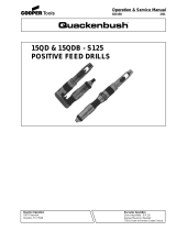
3.2 Operation and functional elements
This section describes the operational and functional elements of the 19RA.
6
1
2
3
4
5
Ref. Description
1 Air Inlet
2 Emergency Stop
3 Hall Effect Sensor
4 Motor and Gearing
5Drill Head Assembly
6 Rear Spindle Guard
7 Spindle Guard
7

Page 12
PL92-5001EN
09/02/2015
Quackenbush®
Accessories
4 Accessories
4.1 Spindles and Spindle Guards
Spindle: Solid or Fluid
Spindle Guard with Guard Cap
Guard Cap
Number Length (in.) Number Length (in.)
Number
382390 9.00
382628 9.00
382391 9.50 624500 7.00
382617 10.75
382708 10.50
382349 12.00
382616 12.00
382631 16.00
623853 16.00
382639 18.00 624403 15.00
Guard Cap Guard Shim *
Number Length (in.) Number Length (in.)
Number Number
------ ---- 624404 4.00
382373 6.750 624505 5.00
------ ---- 624405 6.00
382346 9.000
382599 9.000
382614 11.875 624407 8.00
382607 12.750
623856 11.000
382554 12.000
382636 12.000
382661 15.00
382605 14.500 624506 11.00
------ ---- 624410 12.00
382399 15.000
382555 15.000
382371 16.000
623855 16.000
* Note: Shim thickness = .010", quantity of 2
Spindle
Spindle Guard
Solid Spindles and Guards
624397 6.00
624409 10.00
624411 13.00
624502 14.00
Fluid Spindles and Guards
624359
624406 7.00
624408 9.00
624402 13.00
Spindle
Spindle Guard
624398 8.00
624399 9.00
624359 624358

Page 13
PL92-5001EN
09/02/2015
Quackenbush®
Before Initial Operation
5 Before initial operation
5.1 Ambient conditions
Ambient temperature: 41°F (5°C) to a maximum of 104°F (40°C)
Acceptable relative humidity: 25% to 90%, non-condensing
5.2 Air supply
Excessive air pressure can increase the load and stress on tool parts and drills and make result in
equipment damage.
To attain consistent results, maintain a constant working pressure using a suitable air line unit consisting
of a lter, regulator and lubricator.
ÚThe inside diameter of the air hose must be free of residue, clean if necessary.
ÚSpray a few drops of light air tool oil into the air inlet adapter.
ÚAdjust the lubricator to a minimum setting to reduce the amount of excess oil in the exhaust air.
Oil identification
5.3 Connecting the air supply to the tool
---------------------------------------------------------------------------------------------------------------------------------------
The air hose can disconnect from the tool by itself and whip around uncontrollably.
ÚTurn off the compressed air before connecting to the tool.
ÚSecurely connect the air hose to the tool.
ÚTurn on the compressed air.
---------------------------------------------------------------------------------------------------------------------------------------
Parameter Description
Air Hose
Minimum inside diameter: 1/2" (12,7 mm)
Maximum length: 20' (6,1 m)
Working pressure range
80 to 110 psig (551 to 758 kPa)
Recommended: 90 psi (620 kPa)
Compressed air
Air quality according to ISO 8573-1, quality class 2.4.3
The compressed air must be clean and dry.
Part No. Packaged Designation Vendor
540397 1 Quart (0.94 liter) Airlube 10W/NR-420LB DR Fuchs Lubricants Co.
533485 1 US Gallon (3.78 liter) Airlube 10W/NR-420LB DR Fuchs Lubricants Co.

Page 14
PL92-5001EN
09/02/2015
5.4 Tool set up
The tool must be congured for the application.
5.4.1 Taper-Lok xturing
---------------------------------------------------------------------------------------------------------------------------------------
Danger of injury from accidental start up.
Always disconnect the air supply before installing or removing a cutter and other accessories or
performing any maintenance on the tool.
---------------------------------------------------------------------------------------------------------------------------------------
Customized fixtures are constructed to accept Taper-Lok bushing tips. The 230Q adaptive drill
equipped with a drill bushing tip is inserted into the fixture, twisted and cam-locked into position.
The drill bushing tip’s tapered flanges fit under the shoulder of the lock screws in the fixture. The
drill bushing tip holds the 230Q in alignment and absorbs the thrust and torque of drilling. At the
completion of the drilling cycle, the 230Q is rotated to unlock, withdrawn from the fixture and moved
to the next application.
Several different styles of Taper-Lok fixturing are available. Following are the more common types.
Quackenbush®
Before Initial Operation
Standard Threaded
Drill Bushing Tip
Tool
Nosepiece
Lock
Screws
Tooling
Fixture
Lock Liners
Method for mounting to
a xture. A hole is bored
in the jig to accomodate
the lock liner bushing in
position with the jig.
Direct Mounting
The serrated liner is used
in potted or cast-in-place
installations.
Taper-Lok Bushing

Page 15
PL92-5001EN
09/02/2015
5.4.1 Taper-Lok xturing (continued)
Quackenbush®
Before Initial Operation
Direct Mounting
Most common mounting
method has lock screws
mounted directly into the
xture plate. The shank
of the drill bushing tip ts
directly into a bored hole
in the xture plate.
Lock Strip
This method for closely
spaced holes employes a
lock strip along each side
of the row of holes in the
xture plate. The anges
on the drill bushing tip lock
under the extended edges
of the lock strip.
Taper-Lok Bushing
B - Radius
(for Taper-Lok clamp or lock screw)
Taper-Lok clamp or
lock screw design
1/4-20 hex
head screw
Lock Strip
design
A
Drill Bushing
Tip Series
A B
Tool Nose Thread
(I.D.)
21000 0.312 0.625 3/4 - 16
22000 0.609 0.922 1 - 14
23000 0.734 1.047 1-1/4 - 12
24000 0.859 1.172 1-1/2 - 12
25000 None 1.562 2 - 16
Location Data for Taper-Lok Clamp, Lock Screw and
Lock Strip Mounting

Page 16
PL92-5001EN
09/02/2015
Quackenbush®
First Operation
6 First operation
6.1 Tool function check (refer to section 10 for identication of parts)
1. With the air supply shut off, remove the rear spindle guard.
2. Remove the depth stop (left hand thread)
Keep hands and clothing clear of the rotating spindle.Turn the air supply on and use rapid advance
to remove the spindle.
3. Shut off the air supply
4. Depress the 5/16” diameter steel end of the throttle piston. The throttle piston must spring return
quickly when released.
5. With the air supply on, move the rapid advance lever all the way. The motor will run and the
spindle feed gear (threaded I.D.) must not rotate. The spindle driver gear (splined I.D.) rotates.
The shear pin is whole and intact.
6. Release the rapid advance lever and press the green drill button all the way in to start the
motor. Release the drill button; the motor should continue to run and both gears (splinded and
threaded) rotate.
7. Lift the manual retract lever and release. An audible “snap” indicates the retract valve is shifting
properly. The spindle feed gear (threaded I.D.) stops rotating.
8. Using a screwdriver, depress the signal valve and release. The motor will stop and the retract
valve must reset (manual retract lever should drop). Depress the red stop button slowly. There
should be no venting of air as the stop button is depressed.
9. The lift arm assembly must be intact, undamaged, and in place in the upper block. The lift arm
assembly is factory adjusted (new tool) for little or no play.
10. Press the green drill button and release to start the motor. Press the stop button to stop the
motor. Do not proceed with testing if steps 1 through 10 indicate a malfunction.
11. Keep hands and clothing clear of the rotating spindle. Using the spindle installation tool
(382593), install the spindle with the retract stop collar locked in position. The spindle will
retract fully into the head and the motor will stop automatically. The retract valve must reset
(manual retract lever should drop) and there should be no venting of air when the stop button is
depressed.
12. Screw the depth stop (left hand thread) onto the rear end of th spindle and lock in place. Rapid
advance until the depth stop bears against the back of the drill head. The rapid advance clutch
will “chatter”. The manual retract lever must not rise as the clutch “chatters”. Release the rapid
advance lever.
13. Press the green drill button and release to start the motor. The retract lever rises and the spindle
retracts automatically to the full retract position. The motor will stop automatically.
14. Replace the rear spindle guard.
382593
Spindle Installation Tool

Page 17
PL92-5001EN
09/02/2015
Quackenbush®
First Operation
6.2 Putting into use
The 230Q is designed to drill holes in different material stacks and is for use only with the
Quackenbush DMP control box and should not be connected directly to a standard air line.
Refer to manual PL92-DMP for operation and use of the DMP control box. These instructions must
be read and understood before initiating any drilling operation.
The operating parameters for the tool are programmed using the adaptive interface kit and DMP-
TMS programming software, refer to manual PL92-DMP-PROG for details on programming the tool
memory. These instructions must be read and understood before initiating any drilling operation.
Before mounting any 230Q positive feed drill, check the lock screws in the tooling fixture and drill
bushing. Make sure both are in good condition and securely tightened.
Positive feed drills can exert high torques and high thrust loads. If failure of the lock screws or drill
bushing occurs, the drill may suddenly spin and back away from the drill fixture.
ÚMake sure the cutter is securely installed.
ÚMake sure all guards are in place and secured.
ÚMake sure the 230Q is properly connected to the DMP control box.
ÚMake sure the air supply is securely attached and the compressed is turned on.
6.2.1 Emergency stop
Depressing the red emergency stop button will stop the tool, except when the rapid advance mode is
being utilized. In this situation, releasing the rapid advance lever will stop the tool.
6.2.2 Rapid advance
Depressing the rapid advance lever will advance the cutting tool to the work surface faster than the
regular feed rate and stops advancing automatically until the green drill button is depressed. Note:
When the rapid advance lever is depressed, the exhaust deflector will move forward (toward the drill
head) approximately 3/8” and return to its original position when the lever is released.
6.2.3 Drilling
Press the green drill button firmly and release to start the drilling cycle. The cutter will feed to a
predetermined depth, dwell and then retract. The drill motor will shut offf automatically at the end of
the retract stroke. The cutter may be manually retracted at any time by raising the retract lever.
IMPORTANT: The spindle retracts at a much faster rate than it feeds. Care should be taken to avoid
entrapment.
Do not hold the drill button down during the end of the retract stroke, this prevents the motor from
stopping.
6.2.4 Depth adjustment
The depth collar has four (4) holes for adjusting the depth in increments of .005”. Going from one
hole to the next and using the same slot in the spindle will either increase (clockwise) or decrease
(counterclockwise) the depth by .005”. Using the same hole and rotating the collar 90° will give an
adjustment of .020” and 360° will give an adjustment of .080° Tighten the lock screw after each
depth adjustment. The tip of the lock screw must go into a spindle slot. IMPORTANT NOTE: To
insure maximum repeatability, the work surface, fixtures and depth stop must be cleared of any
chips or foreign material before beginning the next hole. Always replace the rear spindle guard after
making a depth adjustment.

Page 18
PL92-5001EN
09/02/2015
Quackenbush®
Troubleshooting
7 Troubleshooting
Malfunction Possible causes Remedy
No or low air pressure !
Make sure there is adequate air pressure at
the tool air inlet
Reversing ring out of position !
Make sure the reversing ring is in the
clockwise or counterclockwise position
Trip rod spring out of position !Tool disassembly required
Broken gears !
Tool disassembly required (parts
replacement)
Torque set to high !Reduce the torque setting
Working pressure < 58 psi (400 kPa) !Increase the working air pressure
Teeth on adjusting wrench worn or
broken
!Replace adjusting wrench
Teeth on adjustment nut worn or
broken
!
Clutch disassembly required (parts
replacement)
Reduced air pressure !Check air supply line for any obstructions
Lack of lubrication !
Check the air line lubricator to make sure it is
full of lubricant and is working properly
Motor exhaust air is obstructed !Clean or replace bronze mufflers
Swollen rotor blades from excessive
moisture
!
Check the air line filter, empty reservoir if
necessary
Worn rotor blades !
Tool disassembly required (parts
replacement)
Worn gears or bearings !
Tool disassembly required (parts
replacement)
Loose inlet adapter !Tighten inlet adapter
Worn o-ring on inlet adapter !Replace o-ring
Tool does not
start
Tool does not shut
off
Unable to adjust
torque
Tool loses power
Air leak at inlet
adapter

Page 19
PL92-5001EN
09/02/2015
Quackenbush®
Maintenance
8 Maintenance
---------------------------------------------------------------------------------------------------------------------------------------
Danger of injury from accidental start up.
Turn off the compressed air before performing any maintenance.
---------------------------------------------------------------------------------------------------------------------------------------
8.1 Service schedule
Only qualied and trained personnel are permitted to perform maintenance on these tools.
Regular maintenance reduces operating faults, repair costs and downtime. In addition to the following
service schedule, implement a safetu related maintenance program that takes the local regulations for
repair and maintenance for all operating phases of the tool into account.
This maintenance schedule uses values that are valid for most applications. For a specic maintenance
interval, refer to 8.1.1 Calculating a customer-specic maintenance plan.
8.2 Lubricants
For proper function and long service life, use of the correct grease is essential.
Grease lubricants recommended for this tool.
Maintenance
Interval
Rundowns
Daily Daily
!
!
!
!
Visual inspection of air supply hose and connections
Inspect airline filter, regulator and lubricator for proper operation
Check the tool excessive vibration or unusual noises
Visual inspection of all external components of the tool
W1 100,000
!
!
!
!
Inspect the air hose for damage or wear
inspect the square drive output spindle for damage or wear
Inspect the air inlet adapter for a secure fit
Check the maximum free speed
W2 500,000
!
!
!
Check individual parts and replace if necessary
Replace O-rings and seals
Clean bronze mufflers
W3 1,000,000
!
!
!
!
!
!
Check individual parts and replace if necessary
Throttle valve
Motor
Gearing
Clutch (19RAA)
Angle attachment
Designation
Part No. Packaged Designation Vendor
540450 18 oz. (0.51 kg) Black Pearl EP-NLGI-0 Chevron
540395 2 oz. (0.06 kg) Magnalube-G Carleton-Stuart Corp.
513156 16 oz. (0.45 kg) Magnalube-G Carleton-Stuart Corp.
541444 2 oz. (0.06 kg) Rheolube 363AX-1 Nye Lubricants, Inc.
541445 16 oz. (0.45 kg) Rheolube 363AX-1 Nye Lubricants, Inc.

Page 20
PL92-5001EN
09/02/2015
Quackenbush®
Repair Instructions
9 Repair instructions
9.1 Shear pin may shear because:
1. Motor does not stop at full retract, or the retract valve did not reset. Retract collar jams into the
housing cover and the pin shears.
Corrective action does not require disassembly, the spindle may be freed as follows:
• Turn off the air supply
• Remove the tool from the drilling xture
• Using a wrench, rotate the spindle 2 or 3 turns opposite the drilling direction. This will require
high torque.
• When the spindle is free, replace the shear pin. Leave the pin guard in place. Supply air
pressure and rapid advance the spindle out of the drill head.
• Correct the malfunction and run a “Tool Function Check”, see section 6.1.
2. Packed chips or dull cutter may overload the spindle. The feed rate may be too high. Drilling or
reaming may be beyond the torque capability of the tool. These conditions may cause the pin to
shear.
Corrective action:
• Turn off the air supply
• Remove the tool from the drilling xture
• Correct the torque overload problem
• Replace the shear pin
• Make sure the pin guard is in good condition and in place
• Return the tool to service
3. Improper adjustment of the lift arm assembly may prevent automatic retract when the depth stop
contacts the drill head. This condition could cause damage to the gears and shearing of the pin.
Corrective action:
• Tool disassembly is required to replace all damaged drill head parts.
• Reassemble the tool and run a “Tool Function Check”, see section 6.1.
4. Gear teeth have broken, spindle threads have been damaged, or parts inside the drill head have
failed.
Corrective action:
• Tool disassembly is required to replace all damaged drill head parts.
• Reassemble the tool and run a “Tool Function Check”, see section 6.1.
9.2 Spindle installation
IMPORTANT: The retract stop collar must be in place and locked onto the spindle. Install the spindle in
the spindle drive gear and use the spindle tool (382593) to push the spindle in. Depress the green drill
button to start the motor and raise the manual retract lever. The spindle will retract. Release the drill
button. The spindle will continue to retract until the retract stop collar depresses the signal valve and
the tool will automatically shut off.
Note: Do not press the green drill button when the retract stop collar is near or touching the signal valve.
This will prevent the tool from shutting off and will jam the spindle into the head.
/