Mindray DP-5 User manual
- Category
- Measuring, testing & control
- Type
- User manual
This manual is also suitable for

DP-5/DP-7 Series
Digital Ultrasonic Diagnostic Imaging
System
Service Manual
Revision 14.0


i
Table of Content
Table of Content ................................................................................................................... i
Revision History ................................................................................................................... I
Intellectual Property Statement .......................................................................................... II
Applicable for ...................................................................................................................... II
Statement ............................................................................................................................. II
Responsibility on the Manufacturer Party ........................................................................ III
Customer Service Department .......................................................................................... III
1 Preface ....................................................................................................................... 1-1
1.1 Meaning of Signal Words ................................................................................................. 1-1
1.2 Meaning of Symbols......................................................................................................... 1-1
1.2.1 Meaning of Safety Symbols ...................................................................................... 1-1
1.2.2 Warning Labels ......................................................................................................... 1-2
1.2.3 General Symbols ...................................................................................................... 1-2
1.3 Safety Precautions ........................................................................................................... 1-3
1.3.1 Electric Safety .......................................................................................................... 1-3
1.3.2 Mechanical Safety .................................................................................................... 1-4
1.3.3 Personnel Safety ...................................................................................................... 1-5
1.3.4 Others ...................................................................................................................... 1-5
2 Specifications ............................................................................................................ 2-1
2.1 Overview ......................................................................................................................... 2-1
2.1.1 Intended Use ............................................................................................................ 2-1
2.1.2 Introduction of Each Unit ........................................................................................... 2-1
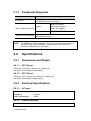
2.1.3 Peripherals Supported .............................................................................................. 2-6
2.2 Specifications ................................................................................................................... 2-6
2.2.1 Dimensions and Weight ............................................................................................ 2-6
2.2.2 Electrical Specifications ............................................................................................ 2-6
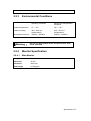
2.2.3 Environmental Conditions ......................................................................................... 2-7
2.2.4 Monitor Specification................................................................................................. 2-7
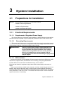
3 System Installation .................................................................................................... 3-1
3.1 Preparations for Installation .............................................................................................. 3-1
3.1.1 Electrical Requirements ............................................................................................ 3-1
3.1.2 Installation Condition ................................................................................................ 3-2
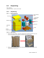
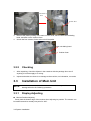
3.2 Unpacking ........................................................................................................................ 3-3
3.2.1 Unpacking ................................................................................................................ 3-3
3.2.2 Checking .................................................................................................................. 3-4
3.3 Installation of Main Unit .................................................................................................... 3-4
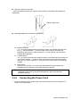
3.3.1 Display Adjusting ...................................................................................................... 3-4
3.3.2 Connecting the Power Cord ...................................................................................... 3-5
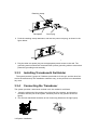
3.3.3 Installing Transducer& Gel Holder ............................................................................. 3-6
3.3.4 Connecting the Transducer ....................................................................................... 3-6
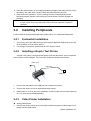
3.4 Installing Peripherals ........................................................................................................ 3-7
3.4.1 Footswitch Installation............................................................................................... 3-7
3.4.2 Installing a Graph / Text Printer ................................................................................. 3-7
3.4.3 Video Printer Installation ........................................................................................... 3-7

ii
3.5 System Configuration ....................................................................................................... 3-8
3.5.1 Running the System ................................................................................................. 3-8
3.5.2 Enter Doppler ........................................................................................................... 3-8
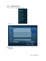
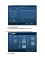
3.5.3 System Preset .......................................................................................................... 3-9
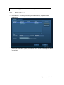
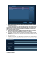
3.5.4 Print Preset ............................................................................................................ 3-11
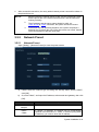
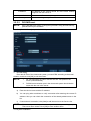
3.5.5 Network Preset ....................................................................................................... 3-13
3.5.6 System Information ................................................................................................. 3-15
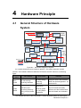
4 Hardware Principle .................................................................................................... 4-1
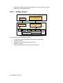
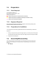
4.1 General Structure of Hardware System ............................................................................ 4-1
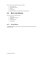
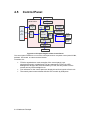
4.2 Main Unit Module ............................................................................................................. 4-2
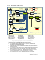
4.2.1 Probe Board ............................................................................................................. 4-2
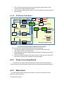
4.2.2 Probe Connecting Board ........................................................................................... 4-4
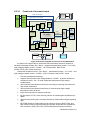
4.2.3 Main board ............................................................................................................... 4-4
4.2.4 IO Interface Board .................................................................................................... 4-7
4.2.5 IO Rear board ........................................................................................................... 4-8
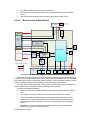
4.3 Power supply Module ....................................................................................................... 4-9
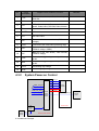
4.3.1 Power Output of the Power supply module and Supporting Function Distribution ...... 4-9
4.3.2 System Power-on Control ....................................................................................... 4-10
4.4 Monitor .......................................................................................................................... 4-13
4.5 Control Panel ................................................................................................................. 4-14
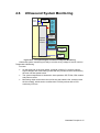
4.6 Ultrasound System Monitoring ....................................................................................... 4-15
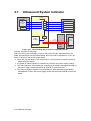
4.7 Ultrasound System Indicator .......................................................................................... 4-16
5 Function Checking and Testing ............................................................................... 5-1
5.1 Preparation ...................................................................................................................... 5-1
5.1.1 Personnel ................................................................................................................. 5-1
5.1.2 Tool .......................................................................................................................... 5-1
5.2 Checking System Status .................................................................................................. 5-1
5.2.1 System Running Status............................................................................................. 5-1
5.2.2 System Running Status............................................................................................. 5-1
5.3 General exam .................................................................................................................. 5-2
5.3.1 Check Flow .............................................................................................................. 5-2
5.3.2 Checking Content ..................................................................................................... 5-2
5.4 Function Checks .............................................................................................................. 5-4
5.4.1 Check Flow .............................................................................................................. 5-4
5.4.2 Checking Content ..................................................................................................... 5-5
5.4.3 Checking Content ..................................................................................................... 5-5
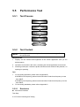
5.5 Performance Test ........................................................................................................... 5-10
5.5.1 Test Process ........................................................................................................... 5-10
5.5.2 Test Content ........................................................................................................... 5-10
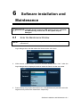
6 Software installation and Maintenance .................................................................... 6-1
6.1 Enter the Maintenance Window .......................................................................................... 6-1
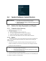
6.2 System Software Install/ Restore ...................................................................................... 6-2
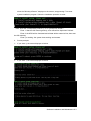
6.2.1 Restore the Operating System and Doppler .............................................................. 6-2
6.2.2 Doppler Restoration .................................................................................................. 6-5
6.3 Installation of Optional Devices ........................................................................................ 6-8
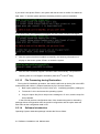
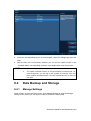
6.4 Data Backup and Storage ................................................................................................ 6-9
6.4.1 Manage Settings....................................................................................................... 6-9
6.4.2 Patient Data Backup and Restore ........................................................................... 6-10
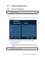
6.5 Software Maintenance ................................................................................................... 6-11

iii
6.5.1 Product Configuration ............................................................................................. 6-11
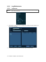
6.5.2 Log Maintenance .................................................................................................... 6-12
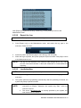
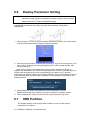
6.6 Display Parameter Setting .............................................................................................. 6-14
6.7 HDD Partition ................................................................................................................. 6-14
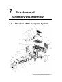
7 Structure and Assembly/Disassembly ..................................................................... 7-1
7.1 Structure of the Complete System .................................................................................... 7-1
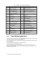
7.2 Field Replaceable Unit ..................................................................................................... 7-2
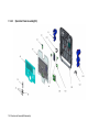
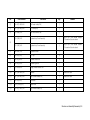
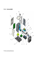
7.2.1 Explosive View ......................................................................................................... 7-3
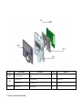
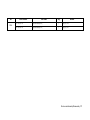
7.2.2 Assembly Explosive View ......................................................................................... 7-4
7.3 Preparation .................................................................................................................... 7-21
7.3.1 Tools Required ....................................................................................................... 7-21
7.3.2 Engineers Required ................................................................................................ 7-21
7.3.3 Preparations for Installation .................................................................................... 7-21
7.4 Assembly/Disassembly .................................................................................................. 7-21
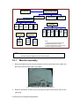
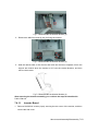
7.4.1 Monitor assembly ................................................................................................... 7-22
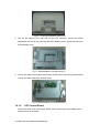
7.4.2 IO Rear board ......................................................................................................... 7-25
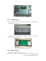
7.4.3 Machine Fan........................................................................................................... 7-25
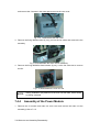
7.4.4 Assembly of the Power Module ............................................................................... 7-26
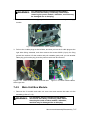
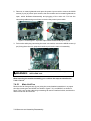
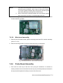
7.4.5 Main Unit Box Module ............................................................................................. 7-27
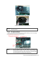
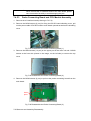
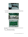
7.4.6 Probe Board Assembly ........................................................................................... 7-31
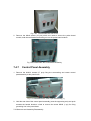
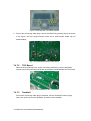
7.4.7 Control Panel Assembly .......................................................................................... 7-32
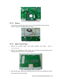
7.4.8 DVD Assembly ....................................................................................................... 7-36
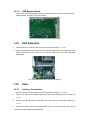
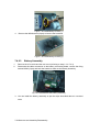
7.4.9 Other ...................................................................................................................... 7-36
8 System Diagnosis and Support ................................................................................ 8-1
8.1 General Status Indicator ................................................................................................... 8-1
8.1.1 The Status Indicators on the Control Panel ............................................................... 8-1
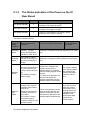
8.1.2 The Status Indicators of the Power on the IO Rear Board .......................................... 8-2
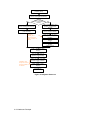
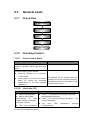
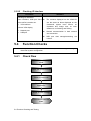
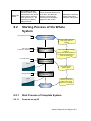
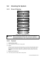
8.2 Starting Process of the Whole System .............................................................................. 8-3
8.2.1 Start Process of Complete System ............................................................................ 8-3
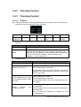
8.2.2 The start-up Process of BIOS ................................................................................... 8-4
8.2.3 The Start-up of Linux ................................................................................................ 8-5
8.2.4 The Start-up of Doppler............................................................................................. 8-5
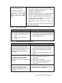
8.3 Alarming and Abnormal Information.................................................................................. 8-8
8.3.1 Turning on the System Configuration File is Abnormal............................................... 8-8
8.3.2 The voltage of system power is abnormal ................................................................. 8-8
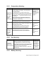
8.3.3 Temperature Alarming ............................................................................................... 8-9
8.3.4 Fan Alarming ............................................................................................................ 8-9
8.3.5 Battery Alarming ....................................................................................................... 8-9
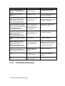
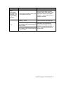
8.3.6 PHV Related Alarming ............................................................................................ 8-10
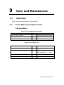
9 Care and Maintenance .............................................................................................. 9-1
9.1 Overview ......................................................................................................................... 9-1
9.1.1 Tools, Measurement Devices and Consumables ....................................................... 9-1
9.1.2 Care and Maintenance Frequency ............................................................................ 9-2
9.2 Cleaning the System ........................................................................................................ 9-3
9.2.1 Flow of Cleaning ....................................................................................................... 9-3
9.2.2 Content .................................................................................................................... 9-3
9.3 Maintenance Check ......................................................................................................... 9-5
9.3.1 System Function ....................................................................................................... 9-5
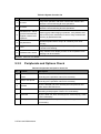
9.3.2 Peripherals and Options Check................................................................................. 9-6

iv
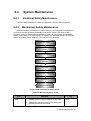
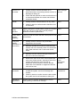
9.4 System Maintenance........................................................................................................ 9-7
9.4.1 Electrical Safety Maintenance ................................................................................... 9-7
9.4.2 Mechanical Safety Maintenance ............................................................................... 9-7
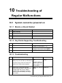
10 Troubleshooting of Regular Malfunctions ............................................................. 10-1
10.1 System cannot be powered on ....................................................................................... 10-1
10.1.1 Module or Board Related ........................................................................................ 10-1
10.1.2 Key Points Supporting Troubleshooting ................................................................... 10-1
10.1.3 Troubleshooting ...................................................................................................... 10-1
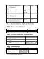
10.2 System Cannot Start up Normally ................................................................................... 10-2
10.2.1 Module or Board Related ........................................................................................ 10-2
10.2.2 Key Points Supporting Troubleshooting ................................................................... 10-2
10.2.3 Troubleshooting ...................................................................................................... 10-2
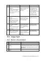
10.3 Image Fault .................................................................................................................... 10-3
10.3.1 Module or Board Related ........................................................................................ 10-3
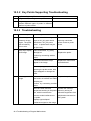
10.3.2 Key Points Supporting Troubleshooting ................................................................... 10-4
10.3.3 Troubleshooting ...................................................................................................... 10-4
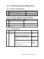
10.4 Probe Socket System Malfunction .................................................................................. 10-5
10.4.1 Module or Board Related ........................................................................................ 10-5
10.4.2 Key Points Supporting Troubleshooting ................................................................... 10-5
10.4.3 Troubleshooting ...................................................................................................... 10-5
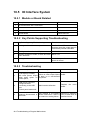
10.5 IO Interface System ....................................................................................................... 10-6
10.5.1 Module or Board Related ........................................................................................ 10-6
10.5.2 Key Points Supporting Troubleshooting ................................................................... 10-6
10.5.3 Troubleshooting ...................................................................................................... 10-6
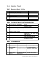
10.6 Control Panel ................................................................................................................. 10-7
10.6.1 Module or Board Related ........................................................................................ 10-7
10.6.2 Key Points Supporting Troubleshooting ................................................................... 10-7
10.6.3 Troubleshooting ...................................................................................................... 10-7
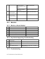
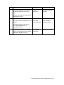
10.7 Monitor .......................................................................................................................... 10-8
10.7.1 Module or Board Related ........................................................................................ 10-8
10.7.2 Key Points Supporting Troubleshooting ................................................................... 10-8
10.7.3 Troubleshooting ...................................................................................................... 10-8
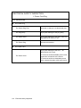
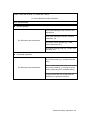
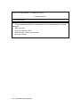
Appendix A ELECTRICAL SAFETY INSPECTION ................................................... A-1
Appendix B Phantom Usage Illustration ................................................................. B-1
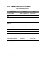
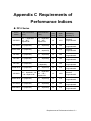
Appendix C Requirements of Performance Indices ............................................... C-1
Appendix D Boot Screen .......................................................................................... D-1

I
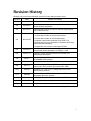
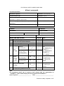
Revision History
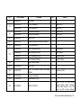
Mindray may revise this publication from time to time without written notice.
Revision Date Reason for Change
1.0 2011.10.25 Initial release
2.0 2012.9.24
Update the test items, test methods and limit values of
electrical safety inspection.
3.0 2013.04.17 Add FRU part number for HDD of different regions/types
(CE/FDA/human/vet)
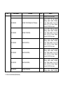
4.0 2013.05.07
In chapter 7.2:
1. Correct part number of dual-encoder board.
2. Correct part number of IO interface board.
3. Replace control panel modules of DP-5/DP-7 by
corresponding top cover assembly of keyboard (including
photos and part numbers).
4. Delete FRU unit of main control panel PCBA.
5.0 2013.6.24 Add “The attentions to the assembly/disassembly, otherwise
the hard disk will be damaged” to Chapter 7.4.9.2
6.0 2015.1.14 Section 7.2, add new main board FRU number and
compatibility description.
7.0 2015.7 Section 2.1.3, add SONY UP-D898MD and SONY
UP-X898MD video printers
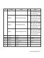
8.0 2016.8 Update the labels in 1.2.2.
9.0 2017.11 In section 7.2, add FRUs: DC-DC board (FRU), AC-DC
board (115V FRU), and AC-DC board (230V FRU)
10.0 2018.01
In section 7.3.1 and 7.4.5.1, modify the main unit fan
disassembling method
11.0 2018.04 In section 7.2, add FRUs: PC module and HDD; and update
information about the printers
12.0 2019.3 Add FRUs: Power Module Assembly and AC-DC board
13.0 2019.08 Add BayTrail PC Module and relevant comments
14.0 2020.12 Add FRU part number of panel base
© 2011-2020 Shenzhen Mindray Bio-medical Electronics Co., Ltd. All Rights Reserved.

II
Intellectual Property Statement
SHENZHEN MINDRAY BIO-MEDICAL ELECTRONICS CO., LTD. (hereinafter called
Mindray) owns the intellectual property rights to this Mindray product and this manual.
This manual may referring to information protected by copyright or patents and does not
convey any license under the patent rights or copyright of Mindray, or of others.
Mindray intends to maintain the contents of this manual as confidential information.
Disclosure of the information in this manual in any manner whatsoever without the written
permission of Mindray is strictly forbidden.
Release, amendment, reproduction, distribution, rental, adaptation, translation or any
other derivative work of this manual in any manner whatsoever without the written
permission of Mindray is strictly forbidden.
,, , , , BeneView,
WATO, BeneHeart, are the trademarks, registered or otherwise, of Mindray in China
and other countries. All other trademarks that appear in this manual are used only for
informational or editorial purposes. They are the property of their respective owners.
Applicable for
This service manual is applicable for the service engineers, authorized service personnel
and service representatives of this ultrasound system.
Statement
This service manual describes the product according to the most complete configuration;
some of the content may not apply to the product you are responsible for. If you have any
questions, please contact Mindray Customer Service Department.
Do not attempt to service this equipment unless this service manual has been consulted
and is understood. Failure to do so may result in personnel injury or product damage.

III
Responsibility on the Manufacturer
Party
Mindray is responsible for the effects on safety, reliability and performance of this product,
only if:
All installation operations, expansions, changes, modifications and repairs of this
product are conducted by Mindray authorized personnel;
The electrical installation of the relevant room complies with the applicable national
and local requirements;
The product is used in accordance with the instructions for use.
Mindray's obligation or liability under this warranty does not include any transportation or
other charges or liability for direct, indirect or consequential damages or delay resulting
from the improper use or application of the product or the use of parts or accessories not
approved by Mindray or repairs by people other than Mindray authorized personnel.
This warranty shall not extend to:
Any Mindray product which has been subjected to misuse, negligence or accident;
Any Mindray product from which Mindray's original serial number tag or product
identification markings have been altered or removed;
Any products of any other manufacturers.
Customer Service Department
WARNING:
It is important for the hospital or organization that employs
this equipment to carry out a reasonable service/maintenance
plan. Neglect of this may result in machine breakdown or
injury of human health.
Manufacturer:
Shenzhen Mindray Bio-Medical Electronics Co., Ltd.
Address:
Mindray Building,Keji 12th Road South,High-tech industrial
park,Nanshan,Shenzhen 518057,P.R.China
Website:
www.mindray.com
E-mail Address:
service@mindray.com
Tel:
+86 755 81888998
Fax:
+86 755 26582680


Preface 1-1
1 Preface
This chapter describes important issues related to safety precautions, as well as the
labels and icons on the ultrasound machine.
1.1 Meaning of Signal Words
In this operator’s manual, the signal words DANGER, WARNING, CAUTION and
NOTE are used regarding safety and other important instructions. The signal words and their
meanings are defined as follows. Please understand their meanings clearly before reading this
manual.
Signal word Meaning
DANGER
Indicates death or serious injury may occur imminently in this
hazardous situation if not avoided.
WARNING
Indicates death or serious injury may occur potentially in this
hazardous situation if not avoided.
CAUTION Indicates minor or moderate injury may occur potentially in this
hazardous situation if not avoided.
NOTE
Indicates property damage may occur potentially in this hazardous
situation if not avoided.
1.2 Meaning of Symbols
The meaning and location of the safety symbols and warning labels on the ultrasound machine
are described in the following tables, please read them carefully before using the system.
1.2.1 Meaning of Safety Symbols
Symbol
Meaning
Location
Type-BF applied part
The ultrasound transducers connected to this system are
type-BF applied parts.
The ECG module connected to this system is Type-BF
applied part.
Below the IO
panel
Caution.

1-2 Preface
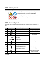
1.2.2 Warning Labels
No.
Warning Labels
Meaning
1.
a. Do not place the device with the mobile trolley on a sloped
surface. Otherwise the device may slide, resulting in
personal injury or the device malfunction. Two persons are
required to move the device over a sloped surface.
b. Do not sit on the device.
c. DO NOT push the device when the casters are locked.
d. Caution! please carefully read this manual before use
system
1.2.3 General Symbols
This system uses the symbols listed in the following table, and their meanings are explained as
well.
No. Symbol Description Location
1 Equipotentiality On the power supply panel
2
Power button On the control panel
3 Network port
On the IO panel
4 USB ports
5 Video Video output
On the IO panel
6 S-Video S-Video output
7 Remote control port
8 Reserved,Audio output
9 VGA signal output
10 Display brightness adjusting On the nether right corner
of the display
11 Display contrast adjusting
12 AC Status Indicator On the upper right corner
of the control panel
13 Battery Status Indicator
a
b
c
d

Preface 1-3
No. Symbol Description Location
14 Standby indicator
15 Hard disk indicator
16
A Probe port A
Below the probe socket
17
B Probe port B
18
C Probe port C
19 Product serial number
Product label
20 Manufacture date
21
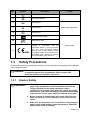
This product is provided with a CE
markin
g in accordance with the
regulations stated in Council Directive
93 / 42 / EEC concerning Medical
Devices. The number adjacent to the
CE marking (0123) is the number of the
EU-
notified body certified for meeting
the requirements of the Directive.
1.3 Safety Precautions
Please read the following precautions carefully to ensure the safety of the patient and the operator
when using the probes.
DANGER Do not operate this system in an atmosphere containing flammable
or explosive gases such as anesthetic gases, oxygen, and
hydrogen because an explosion may occur.
1.3.1 Electric Safety
WARNING: 1.
Connect the adapter power plug of this system and power
plugs of the peripherals to wall receptacles that meet the
ratings indicated on the rating nameplate. Using a
multifunctional receptacle may affect the system grounding
performance, and cause the leakage current to exceed safety
requirements. Use the power cable provided with this system.
2.
Before cleaning or disassembling the system, disconnect the
power cord from the socket. Otherwise, it may cause electric
shock.
3. Make sure all connections are correct before connecting the
power supply cable during system maintenance. Otherwise
damage may result by hot plug.

1-4 Preface
4.
Do not use this system simultaneously with equipment such
as an electrosurgical unit, high-frequency therapy
equipment, or a defibrillator, etc.; otherwise electric shock
may result.
5. This system is not water-proof. If any water is sprayed on or
into the system, electric shock may result.
CAUTION: 1.
DO NOT connect or disconnect the system’s power cord or
its accessories (e.g., a printer or a recorder) without turning
OFF the power first. This may damage the system and its
accessories or cause electric shock.
2.
Avoid electromagnetic radiation when perform performance
test on the ultrasound system.
3. In an electrostatic sensitive environment, don’t touch the
device directly. Please wear electrostatic protecting gloves if
necessary,
4. You should use the ECG lead wires provided with the ECG
module. Otherwise it may result in electric shock.
1.3.2 Mechanical Safety
WARNING:
1.
When this system is moved, please hold the handle. If other
parts of the system are held, it may cause damage due to the
abnormal force. Do not push the system from the left/right
side; otherwise, it may be toppled over.
2.
Do not subject the transducers to knocks or drops. Use of a
defective transducer may cause an electric shock.
CAUTION:
1.
When move the system on the steps, fasten and fully secure
any peripheral device before moving the system, please take
care to prevent the system from toppling.
2.
Do not expose the system to excessive vibration (during the
transportation) to avoid device dropping, collision, or
mechanical damage.
3.
Please install the system on a flat plane with the four casters
locked. Otherwise, damage may be resulted by accidental
moving.
4.
Move the system only when the system is turned off or in
standby mode, otherwise damage may result to the hard disk.

Preface 1-5
1.3.3 Personnel Safety
NOTE: 1. The user is not allowed to open the covers and panel of the system, neither
device disassemble is allowed.
2.
To ensure the system performance and safety, only Mindray engineers or
engineers authorized by Mindray can perform maintenance.
3.
Only technical professionals from Mindray or engineers authorized by Mindray
after training can perform system maintenance.
1.3.4 Others
NOTE:
For detailed operation and other information about the ultrasound system, please
refer to the operator’s manual.


Specifications 2-1
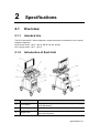
2 Specifications
2.1 Overview
2.1.1 Intended Use
The DC-5 Series/DC-7 Series diagnostic ultrasound system is intended for use in clinical
ultrasonic diagnosis.
DP-5 Series model:DP-5、DP-5T, D P -5E, DP-5S, DP-5B
DP-7 Series model:DP-7、DP-7T
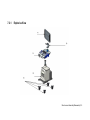
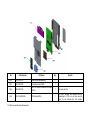
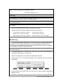
2.1.2 Introduction of Each Unit
No. Name Function
1. LCD Display
Displays the image and parameters during scanning (tilt
angle adjustable)
2.
Control Panel
Refer to the 2.1.2.3 Control Panel
.
3. Support arm Used to support the control panel and the display(Only
DP-7series support)

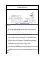
2-2 Specifications
No.
Name
Function
4.
Probe and gel
holder
Used to place the probe or gel
5. Handle Used for pushing when moving the system.
6.
Support arm control
handle
Used to adjust the height of support arm (Only DP-7 series
support)
7. DVD-RW Read and Write DVD drive
8. Probe ports Used to connect the probe
9.
Placing table
Used to place objects or video printer
10. Display support arm Used to support and adjust the position of display
11. IO Panel Interface panel used for inputting and outputting signals,
refer to 2.1.2.1 IO Panel.
12.
Power supply panel
Electrical port panel, refer to 2.1.2.2 Power Supply Panel.
13. Caster Used to secure or move the system.
14. Probe cable hook Used to place and fix the probe cable.
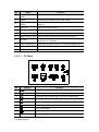
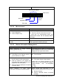
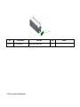
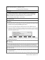
2.1.2.1 IO Panel
No.
Symbol
Function
1
USB ports
2
Separate video output, connecting video printer
3
Composite video signal output, connecting video printer
4
Remote control port
5
Audio output (left channel)
6
Audio output (right channel)
7
VGA signal output
8
Network port
9 1、2、3 Power indicators for 12V, 5V and 3.3V

Specifications 2-3
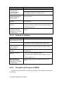
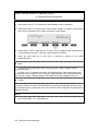
2.1.2.2 Power Supply Panel
No.
Name
Function
1 Equipotential
terminal
Used for equipotential connection, that balances the protective
earth potentials between the system and other electrical
equipment.
2
Auxiliary Power
outlet Supply power for optional peripheral devices
3 Power inlet AC power inlet
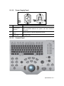
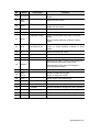
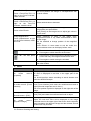
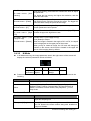
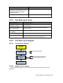
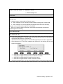
2.1.2.3 Control Panel
<2>
<3
>
<1>

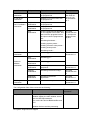
2-4 Specifications
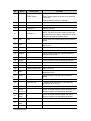
No.
Name
Description
Function
1 / Power button
Off: when system is turned off;
Green: when system is turned on by pressing
this button;
Orange: when system is in standby.
2 / Indicator 1 AC power supply indicator
3 / Indicator 2 Battery status indicator
4
/
Indicator 3
Standby indicator
5 / Indicator 4
HDD status indicator
NOTE: DO NOT move the machine when the
indicator blinking in green. Otherwise the HDD
may be damaged by sudden shake.
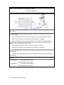
6 Esc
Exit
Press to exit the current status to the previous
status.
7 Help
/
Press to open or close the accompanying help
documents.
8 Review / Press to review the stored images.
9
Report
/
Press to open or close the diagnosis reports.
10 iStation / Press to enter or exit the patient information
management system.
11 F1~F4 User-defined key You can assign a function to the key.
12
Biopsy
/
Press to show or hide the biopsy guide line.
13 Setup / Press to open/close the setup menu.
14
Del
/
Press to delete the comment, etc.
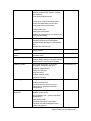
15 / Alphanumeric keys Same as on PC
16 Menu
Main menu
Press to display or hide a mode-specific
parameter menu.
17 Arrow
/
Press to enter or exit the arrow comment
status.
18 Cine Cine Review Press to enter or exit the Cine Review status.
19 /
Direction key
To adjust LCD brightness or contrast when
pressing with <Fn> key.
20 TGC / Move to adjust time gain compensation.
21 Focus
Freq./THI / Press: to switch between Focus and Freq./THI;
Rotate: to adjust corresponding parameter
22
Depth
Zoom /
Press: to switch between Depth and Zoom;
Rotate: to adjust corresponding parameter
23 Patient Patient Information Press to open/ exit patient information screen.
24 Body
Mark
/
Press to enter or exit the Body Mark status.
25
Probe
Probe switch
Press to switch Probe and Exam Type
Page is loading ...
Page is loading ...
Page is loading ...
Page is loading ...
Page is loading ...
Page is loading ...
Page is loading ...
Page is loading ...
Page is loading ...
Page is loading ...
Page is loading ...
Page is loading ...
Page is loading ...
Page is loading ...
Page is loading ...
Page is loading ...
Page is loading ...
Page is loading ...
Page is loading ...
Page is loading ...
Page is loading ...
Page is loading ...
Page is loading ...
Page is loading ...
Page is loading ...
Page is loading ...
Page is loading ...
Page is loading ...
Page is loading ...
Page is loading ...
Page is loading ...
Page is loading ...
Page is loading ...
Page is loading ...
Page is loading ...
Page is loading ...
Page is loading ...
Page is loading ...
Page is loading ...
Page is loading ...
Page is loading ...
Page is loading ...
Page is loading ...
Page is loading ...
Page is loading ...
Page is loading ...
Page is loading ...
Page is loading ...
Page is loading ...
Page is loading ...
Page is loading ...
Page is loading ...
Page is loading ...
Page is loading ...
Page is loading ...
Page is loading ...
Page is loading ...
Page is loading ...
Page is loading ...
Page is loading ...
Page is loading ...
Page is loading ...
Page is loading ...
Page is loading ...
Page is loading ...
Page is loading ...
Page is loading ...
Page is loading ...
Page is loading ...
Page is loading ...
Page is loading ...
Page is loading ...
Page is loading ...
Page is loading ...
Page is loading ...
Page is loading ...
Page is loading ...
Page is loading ...
Page is loading ...
Page is loading ...
Page is loading ...
Page is loading ...
Page is loading ...
Page is loading ...
Page is loading ...
Page is loading ...
Page is loading ...
Page is loading ...
Page is loading ...
Page is loading ...
Page is loading ...
Page is loading ...
Page is loading ...
Page is loading ...
Page is loading ...
Page is loading ...
Page is loading ...
Page is loading ...
Page is loading ...
Page is loading ...
Page is loading ...
Page is loading ...
Page is loading ...
Page is loading ...
Page is loading ...
Page is loading ...
Page is loading ...
Page is loading ...
Page is loading ...
Page is loading ...
Page is loading ...
Page is loading ...
Page is loading ...
Page is loading ...
Page is loading ...
Page is loading ...
Page is loading ...
Page is loading ...
Page is loading ...
Page is loading ...
Page is loading ...
Page is loading ...
Page is loading ...
Page is loading ...
Page is loading ...
Page is loading ...
Page is loading ...
Page is loading ...
Page is loading ...
Page is loading ...
Page is loading ...
Page is loading ...
Page is loading ...
Page is loading ...
Page is loading ...
Page is loading ...
Page is loading ...
Page is loading ...
Page is loading ...
Page is loading ...
Page is loading ...
Page is loading ...
Page is loading ...
Page is loading ...
Page is loading ...
Page is loading ...
Page is loading ...
Page is loading ...
Page is loading ...
Page is loading ...
Page is loading ...
Page is loading ...
Page is loading ...
Page is loading ...
Page is loading ...
Page is loading ...
Page is loading ...
Page is loading ...
Page is loading ...
-
 1
1
-
 2
2
-
 3
3
-
 4
4
-
 5
5
-
 6
6
-
 7
7
-
 8
8
-
 9
9
-
 10
10
-
 11
11
-
 12
12
-
 13
13
-
 14
14
-
 15
15
-
 16
16
-
 17
17
-
 18
18
-
 19
19
-
 20
20
-
 21
21
-
 22
22
-
 23
23
-
 24
24
-
 25
25
-
 26
26
-
 27
27
-
 28
28
-
 29
29
-
 30
30
-
 31
31
-
 32
32
-
 33
33
-
 34
34
-
 35
35
-
 36
36
-
 37
37
-
 38
38
-
 39
39
-
 40
40
-
 41
41
-
 42
42
-
 43
43
-
 44
44
-
 45
45
-
 46
46
-
 47
47
-
 48
48
-
 49
49
-
 50
50
-
 51
51
-
 52
52
-
 53
53
-
 54
54
-
 55
55
-
 56
56
-
 57
57
-
 58
58
-
 59
59
-
 60
60
-
 61
61
-
 62
62
-
 63
63
-
 64
64
-
 65
65
-
 66
66
-
 67
67
-
 68
68
-
 69
69
-
 70
70
-
 71
71
-
 72
72
-
 73
73
-
 74
74
-
 75
75
-
 76
76
-
 77
77
-
 78
78
-
 79
79
-
 80
80
-
 81
81
-
 82
82
-
 83
83
-
 84
84
-
 85
85
-
 86
86
-
 87
87
-
 88
88
-
 89
89
-
 90
90
-
 91
91
-
 92
92
-
 93
93
-
 94
94
-
 95
95
-
 96
96
-
 97
97
-
 98
98
-
 99
99
-
 100
100
-
 101
101
-
 102
102
-
 103
103
-
 104
104
-
 105
105
-
 106
106
-
 107
107
-
 108
108
-
 109
109
-
 110
110
-
 111
111
-
 112
112
-
 113
113
-
 114
114
-
 115
115
-
 116
116
-
 117
117
-
 118
118
-
 119
119
-
 120
120
-
 121
121
-
 122
122
-
 123
123
-
 124
124
-
 125
125
-
 126
126
-
 127
127
-
 128
128
-
 129
129
-
 130
130
-
 131
131
-
 132
132
-
 133
133
-
 134
134
-
 135
135
-
 136
136
-
 137
137
-
 138
138
-
 139
139
-
 140
140
-
 141
141
-
 142
142
-
 143
143
-
 144
144
-
 145
145
-
 146
146
-
 147
147
-
 148
148
-
 149
149
-
 150
150
-
 151
151
-
 152
152
-
 153
153
-
 154
154
-
 155
155
-
 156
156
-
 157
157
-
 158
158
-
 159
159
-
 160
160
-
 161
161
-
 162
162
-
 163
163
-
 164
164
-
 165
165
-
 166
166
-
 167
167
-
 168
168
-
 169
169
-
 170
170
-
 171
171
-
 172
172
-
 173
173
-
 174
174
-
 175
175
-
 176
176
-
 177
177
-
 178
178
-
 179
179


Mindray DP-5 User manual
- Category
- Measuring, testing & control
- Type
- User manual
- This manual is also suitable for
Ask a question and I''ll find the answer in the document
Finding information in a document is now easier with AI
Related papers
-
Mindray DP-30 Series User manual
-
-
-
-
-
Mindray M9 User manual
-
-
-
-
Other documents
-
Lenovo Y27Q-30 User manual
-
Gima 33989 Owner's manual
-
Lenovo G34w-30 Owner's manual
-
 Riden Constant RD6006/ RD6006-W Voltage and Constant Current DC Power Supply User manual
-
PerfectPrime AI200 User manual
-
Pecron S1000 User manual
-
-
 AirTek PCMH45 User manual
-
Giani mipal User manual

