
3A7467C
EN
Instructions
EcoQuip 2
™
EQs, EQc, and EQ Trailer Unit
Vapor Abrasive Blast System
Vapor abrasive blast system for coating removal and surface preparation.
For professional use only.
175 psi (12.06 bar, 1.2 MPa) Maximum Working Pressure
See page 4 for models and approval information.
Important Safety Instructions
Read all warnings and instructions in this
manual before using this equipment.
Save these instructions.
WLD
WLLD

2 3A7467C
Contents
Related Manuals . . . . . . . . . . . . . . . . . . . . . . . . . . . 3
Models . . . . . . . . . . . . . . . . . . . . . . . . . . . . . . . . . . . 4
Packages . . . . . . . . . . . . . . . . . . . . . . . . . . . . . . . . . 5
Warnings . . . . . . . . . . . . . . . . . . . . . . . . . . . . . . . . . 6
Component Identification . . . . . . . . . . . . . . . . . . . 10
MediaTrak Controls . . . . . . . . . . . . . . . . . . . . . . 11
Installation . . . . . . . . . . . . . . . . . . . . . . . . . . . . . . . 12
Grounding (ATEX systems only) . . . . . . . . . . . . 12
Lifting the System . . . . . . . . . . . . . . . . . . . . . . . 12
Blast Hose Control Selection . . . . . . . . . . . . . . 13
Blasting on Higher Surfaces . . . . . . . . . . . . . . . 13
Pinch Hose Inspection . . . . . . . . . . . . . . . . . . . 13
Connect the Blast Hose and Air Hose . . . . . . . 14
Setup . . . . . . . . . . . . . . . . . . . . . . . . . . . . . . . . . . . . 16
Fill the Water Tank . . . . . . . . . . . . . . . . . . . . . . 16
Fill Pot with Abrasive Media . . . . . . . . . . . . . . . 17
Pressurize the Pot . . . . . . . . . . . . . . . . . . . . . . . 18
Operation . . . . . . . . . . . . . . . . . . . . . . . . . . . . . . . . 19
Pressure Relief Procedure . . . . . . . . . . . . . . . . 19
Adjust Blast Pressure . . . . . . . . . . . . . . . . . . . . 20
Adjust Abrasive Media . . . . . . . . . . . . . . . . . . . 21
Refill Pot with Media . . . . . . . . . . . . . . . . . . . . . 21
Set the Abrasive Metering Value . . . . . . . . . . . 22
Optimize the Abrasive Metering Value . . . . . . . 22
General Application Guides . . . . . . . . . . . . . . . 23
Nozzle Selection Guide . . . . . . . . . . . . . . . . . . . 24
Blast Pressure vs. Air Flow Guide . . . . . . . . . . . 24
Use the Wash Feature . . . . . . . . . . . . . . . . . . . 25
Standby . . . . . . . . . . . . . . . . . . . . . . . . . . . . . . . 26
Shutdown . . . . . . . . . . . . . . . . . . . . . . . . . . . . . 26
Drain the Pot . . . . . . . . . . . . . . . . . . . . . . . . . . . 27
Winterize the Equipment . . . . . . . . . . . . . . . . . . 28
Clean the Water Tank . . . . . . . . . . . . . . . . . . . . 29
Use the Water Dose Meter . . . . . . . . . . . . . . . . 29
Troubleshooting . . . . . . . . . . . . . . . . . . . . . . . . . . 30
Repair . . . . . . . . . . . . . . . . . . . . . . . . . . . . . . . . . . . 36
Replace the DataTrak Battery . . . . . . . . . . . . . . 36
Replace the DataTrak Fuse . . . . . . . . . . . . . . . 37
Replace the Pinch Hose . . . . . . . . . . . . . . . . . . 38
Parts . . . . . . . . . . . . . . . . . . . . . . . . . . . . . . . . . . . . 40
EQs Parts . . . . . . . . . . . . . . . . . . . . . . . . . . . . . 40
EQc and EQ200T / EQ400T Models . . . . . . . . . 44
EQ200T Parts . . . . . . . . . . . . . . . . . . . . . . . . . . 46
EQ400T Parts . . . . . . . . . . . . . . . . . . . . . . . . . . 48
Enclosure Box Parts . . . . . . . . . . . . . . . . . . . . . 50
Enclosure Parts . . . . . . . . . . . . . . . . . . . . . . . . . 54
Blast Hoses . . . . . . . . . . . . . . . . . . . . . . . . . . . . 56
Vapor Abrasive Blast Systems and
Accessories . . . . . . . . . . . . . . . . . . . . . . . . . . . 58
50 ft (15 m) Blast Hoses with Control
Hose/Cable . . . . . . . . . . . . . . . . . . . . . . . . . 58
50 ft (15 m) Blast Hoses without Control
Hose/Cable . . . . . . . . . . . . . . . . . . . . . . . . . 58
Control Hoses/Cable with Blast Hose . . . . . . . . 58
Nozzles . . . . . . . . . . . . . . . . . . . . . . . . . . . . . . . 59
EQ200T (M58 Kaeser Compressor) . . . . . . . . . 59
EQ400T (Atlas Copco Compressor) . . . . . . . . . 59
Other Accessories . . . . . . . . . . . . . . . . . . . . . . . 59
Common Spare Parts . . . . . . . . . . . . . . . . . . . . 60
Tubing Schematic . . . . . . . . . . . . . . . . . . . . . . . . . 61
Dimensions . . . . . . . . . . . . . . . . . . . . . . . . . . . . . . . 62
EQs and EQs Elite Models . . . . . . . . . . . . . . . . 62
EQc Models . . . . . . . . . . . . . . . . . . . . . . . . . . . . 62
EQ Trailer Models . . . . . . . . . . . . . . . . . . . . . . . 63
Trailer Kit Compressor Installation Guidelines
(279960, 279970) . . . . . . . . . . . . . . . . . . . . 64
Trailer Mounting Area Dimensions . . . . . . . . . . 64
Technical Specifications . . . . . . . . . . . . . . . . . . . . 66
EQs Elite . . . . . . . . . . . . . . . . . . . . . . . . . . . . . . 66
EQc and EQc Elite . . . . . . . . . . . . . . . . . . . . . . . 67
EQ200T Elite . . . . . . . . . . . . . . . . . . . . . . . . . . . 68
EQ400T Elite . . . . . . . . . . . . . . . . . . . . . . . . . . . 69
California Proposition 65 . . . . . . . . . . . . . . . . . . 69
Graco Standard Warranty . . . . . . . . . . . . . . . . . . . 70

Related Manuals
3A7467C 3
Related Manuals
Manual in
English Description
3A3489
EcoQuip EQm Vapor Abrasive
Blast System
313840
DataTrak
™
333397 Pump
335035 Air Inlet Kit
309474 Low Pressure Fluid Regulators
3A3470 Hose Rack Kit
3A3838 Nozzle Pressure Verification Kit
3A3839 Nozzle Extension Handle Kit
3A3970 Water Dose Kit

Models
4 3A7467C
Models
EcoQuip 2 Vapor Blast Systems
Model
Part
Number
Series
Blast Control
Approvals
Blast
Hose
Nozzle
Pneumatic Electric
EQs
262960 D
262964 C
100 ft,
1.25 in. ID
#8 High
Performance
EQs Elite
262970 D
262974 C
100 ft,
1.25 in. ID
#8 High
Performance
EQc
273200 D
273209 C
50 ft,
1.25 in. ID
#8 Standard
EQc Elite
273204 D
273214 A
273210 C
50 ft,
1.25 in. ID
#8 High
Performance
EQ200t
Elite
279990 C
Tier 4 final
EQ400t
Elite
279980 C
Tier 4 final
II 2 G Ex ia h IIA T3 Gb X
II 2 G Ex ia h IIA T3 Gb X
II 2 G Ex ia h IIA T3 Gb X
II 2 G Ex ia h IIA T3 Gb X

Packages
3A7467C 5
Packages
NOTE: Packages include a blast hose with electric or pneumatic blast controls and a tool kit.
EcoQuip 2 Vapor Blast System Packages
Model Package
Included
System
Blast Control
Blast Hose Nozzle
Pneumatic Electric
EQs
262962
262960
100 ft, 1.25 in. ID
#8 High
Performance
262963
EQs Elite
262972
262970
100 ft, 1.25 in. ID
#8 High
Performance
262973
EQc
273202
273200
50 ft, 1.25 in. ID #8 Standard
273203
EQc Elite
273206
273204
50 ft, 1.25 in. ID
#8 High
Performance
273208

Warnings
6 3A7467C
Warnings
The following warnings are for the setup, use, grounding, maintenance, and repair of this equipment. The
exclamation point symbol alerts you to a general warning and the hazard symbols refer to procedure-specific risks.
When these symbols appear in the body of this manual or on warning labels, refer back to these Warnings.
Product-specific hazard symbols and warnings not covered in this section may appear throughout the body of this
manual where applicable.
WARNING
SPECIFIC CONDITIONS OF USE (ATEX systems only)
• Ground all equipment in the work area. See Grounding (ATEX systems only) Instructions.
• All label and marking material must be cleaned with a damp cloth (or equivalent).
DUST AND DEBRIS HAZARD
Use of this equipment can result in the release of potentially harmful dust or toxic substances from the
abrasive being used, the coatings being removed, and the base object being blasted.
• For use only by sophisticated users familiar with applicable governmental safety and industrial
hygiene regulations.
• Use equipment only in a well-ventilated area.
• Wear a properly fit-tested and government approved respirator suitable for the dust conditions.
• Follow local ordinances and/or regulations for disposal of toxic substances and debris.
PRESSURIZED EQUIPMENT HAZARD
Fluid from the equipment, leaks, or ruptured components can splash in the eyes or on skin an cause
serious injury.
• Follow the Installation when you stop spraying/dispensing and before cleaning, checking, or
servicing equipment.
• Tighten all fluid connections before operations the equipment.
• Check hoses, tubes, and couplings daily. Replace worn or damaged parts immediately.

Warnings
3A7467C 7
EQUIPMENT MISUSE HAZARD
Misuse can cause death or serious injury.
• Do not operate the unit when fatigued or under the influence of drugs or alcohol.
• Do not exceed the maximum working pressure of temperature rating of the lowest rated system
component. See Technical Specifications in the equipment manuals.
• Do not use this equipment without hose restraints and coupler pins installed on all air and blast hose
couplings.
• Do not blast unstable objects. The high amount of fluid flow from the nozzle can potentially move
heavy objects.
• Do not exceed load ratings of lift eyes.
• Do not operate equipment on or stand on an unstable support. Keep effective footing and balance at
all times.
• Use fluids and solvents that are compatible with equipment wetted parts. See Technical
Specifications in all equipment manuals. Read fluid and solvent manufacturer’s warnings. For
complete information about your material, request Safety Data Sheets (SDSs) from distributor
retailer.
• Never use 1, 1, 1-trichloroethane, methylene chloride, other halogenated hydrocarbon solvents or
fluids containing such solvents in pressurized aluminum equipment. Such use could result in a
chemical reaction, with the possibility of explosion.
• Do not leave the work area while equipment is energized or under pressure.
• Turn off all equipment and follow the Installation when equipment is not in use.
• Check equipment daily. Repair or replace worn or damaged parts immediately with genuine
manufacturer’s replacement parts only.
• Do not alter or modify equipment. Alterations or modifications may void agency approvals and create
safety hazards.
• Make sure all equipment is rated and approved for the environment in which you are using it.
• Use equipment only for its intended purpose. Call your distributor for information.
• Route hoses and cables away from traffic areas, sharp edges, moving parts, and hot surfaces.
• Do not kink or over bend hoses or use hoses to pull equipment.
• Keep children and animals away from work area.
• Comply with all applicable safety regulations.
BURN HAZARD
Equipment surfaces and fluid that is heated can become very hot during operation. To avoid severe
burns:
• Do not touch hot fluid or equipment.
FIRE AND EXPLOSION HAZARD
Flammable fumes, such as solvent, in work area can ignite or explode. To help prevent fire and
explosion:
• Use equipment only in well ventilated areas.
• Abrasive material exiting blast nozzle can generate sparks. When flammable liquids are used near
the blast nozzle or for flushing or cleaning, keep the blast nozzle at least 20 feet (6 meters) away from
explosive vapors.
• Ground all equipment in the work area. See Grounding (ATEX systems only) instructions.
• Keep work area free of debris, including solvent, rags and gasoline.
• Keep a working fire extinguisher in the work area.
WARNING

Warnings
8 3A7467C
MOVING PARTS HAZARD
Moving parts can pinch, cut, or amputate fingers and other body parts.
• Keep clear of moving parts.
• Do not operate equipment with protective guards or covers removed.
• Pressurized equipment can start without warning. Before checking, moving, or servicing equipment,
follow the Installation and disconnect all power sources.
PERSONAL PROTECTIVE EQUIPMENT
Wear appropriate protective equipment when in the work area to help prevent serious injury, including
eye injury, hearing loss, inhalation of toxic fumes, and burns. Protective equipment includes but is not
limited to:
• Protective eyewear and hearing protection
• Protective clothing, shoes and gloves
• Properly fit-tested and government approved respirator subtable for the dust conditions
RECOIL HAZARD
Blast nozzle may recoil when triggered. If you are not standing securely, you could fall and be seriously
injured.
WARNING

Warnings
3A7467C 9

Component Identification
10 3A7467C
Component Identification
WLD
WLLD
;;
=/
$
3
=+
%
&
(
)
*
+
-
.
/
1
4
5
6
7
8
9
:
;
<
=
=$
=%
=&
='
0
=(
=)
%
=*

Component Identification
3A7467C 11
MediaTrak Controls
Key:
A Frame
B Blast Control Switch
B2 Blast Nozzle
C Blast Hose
E Pot
F Pop-up Handle
G Water Tank
H Water Tank Lid
J Pot Dump Valve
K Pressure Relief Valve
L Pot Pressure Gauge
M Abrasive Ball Valve
N Inlet Ball Valve
P Control Box
Q Emergency Stop
R Blast Air Regulator
S Water Dose Valve
T Abrasive Metering Valve
U Water Pump Inlet Filter
V Blast Air Pressure Gauge
W Selector Valve
X Rinse Ball Valve
Y Air Supply Connection
Z Blast Connection
ZA Pneumatic Control Connection
ZB Electric Control Connection
(non-ATEX systems only)
ZC Supply Pressure Gauge
ZD MediaTrak
ZE Accessory Extension Hose
ZF Abrasive Material (not included)
ZG Pot Outlet Manifold
ZH Ground Wire and Clamp
(ATEX systems only)
XX Pop-up Seal
ZL Quick Drain Valve
Key:
PK Power Key
CPM Cycle/Rate
GT Grand Totalizer
WLD
8800000
*7
3.
15
&30

Installation
12 3A7467C
Installation
Grounding (ATEX systems only)
Systems: Use supplied ground wire and clamp
(237686).
Air and fluid hoses: Use only genuine Graco
conductive blast hoses with a maximum of 150 ft (45 m)
combined blast hose length to ensure grounding
continuity. Check the electrical resistance of the blast
hoses. If the total resistance to ground exceeds 29
megaohms, replace the blast hose immediately.
Air compressor: Follow manufacturer’s
recommendations.
Lifting the System
• Only lift the system using all available lift points.
During an EQs system lift, the lift chains must be
angled at least 45° from the horizontal.
• Before lifting the system, drain the water tank and
pot of water and media.
• Lift the system with a lift apparatus rated
appropriately for the weight of the system. See
Technical Specifications, page 66.
• Lift the system using the lift eyes shown on the
appropriate illustration.
EQs and EQs Elite Models:
EQc Models:
The equipment must be grounded to reduce the risk
of static sparking. Static sparking can cause fumes to
ignite or explode. Grounding provides an escape wire
for the electric current.
WLD
WLE

Installation
3A7467C 13
Blast Hose Control Selection
Make sure to use the correct type of blast control. Either
an electric or pneumatic blast control switch can be
used with hose lengths less than 150 ft (45 m). Blasting
with 150 ft (45 m) or more of blast hose requires the use
of an electric blast control switch.
Blasting on Higher Surfaces
For example: When blasting 50 feet (15 m) straight up,
use at least 10 feet (3 m) of blast hose on the ground
before the blast hose goes up to the blasting height.
Pinch Hose Inspection
Inspect the pinch hose at the start of each job looking
for “bubbles” in the outer casing. If bubbles in the casing
are found, replace the pinch hose (see Replace the
Pinch Hose, page 38). Keep a spare pinch hose on the
job site in case of failure. See Vapor Abrasive Blast
Systems and Accessories, page 58.
NOTE: There are three main factors that can affect
(diminish) the life of the pinch hose: abrasive media
used (course/sharp), blast control switch trigger rate
(high), and the air inlet pressure to the system (high). If
your setup reflects one or more of these factors, inspect
the pinch hose at the start of each job, and weekly
thereafter for signs of failure (bubbling).
NOTICE
When blasting on a surface higher than the
equipment, make sure that there is a length of blast
hose on the ground equal to 10-20% of the height.
The hose on the ground prevents unspent abrasive in
the hose from backing up into the internal plumbing of
the panel, which can cause damage to the main air
regulator when the blast switch is disengaged.
WLE
RI+HLJKW
+HLJKW

Installation
14 3A7467C
Connect the Blast Hose and Air
Hose
1. ATEX models only: Connect the grounding cable
to the external ground stud on the enclosure, then
connect the clamp to a true earth ground.
2. Always purge the air supply hose for 15-20 seconds
before connecting the air supply hose from the
compressor (or on-site compressed air source) to
the panel. Make sure all debris is cleared from the
hose.
3. Connect an appropriately sized air supply hose to
the air inlet and install coupler pins. See Technical
Specifications, page 66.
4. Open the compressor air supply valve (175 psi,
12.06 Bar, 1.2 MPa maximum compressor supply).
NOTE: Make sure the air supply meets the
appropriate air flow requirements. See Technical
Specifications, page 66.
WLE
OFF
RUN
START
WLG
NOTICE
Damage to the tubing connections on the blast
control can occur if the blast circuit is allowed to
rotate. To avoid damage, use the supplied wrench to
hold the blast circuit nut inside the enclosure while
installing fittings to the air inlet and blast hose
connections.
WLG
WLD

Installation
3A7467C 15
5. Connect the blast hose, hose restraints, control
hoses, and coupler pins.
Failure to fully secure the blast hoses may cause
hoses to detach during operation. To help prevent
serious injury from flying debris, always install the
blast hose restraints and coupler pins.
WLF
NOTICE
Do not use a wrench when installing the nozzle.
Damage to the seal could occur. To avoid seal
damage, always hand-tighten the nozzle.
WLE

Setup
16 3A7467C
Setup
Fill the Water Tank
1. Fill the water tank with fresh water only, then open
the inlet ball valve (N).
2. Close the rinse ball valve (X) and abrasive ball valve
(M).
3. Turn the selector valve to OFF.
4. Disengage the emergency stop (Q).
NOTE: The water pump will not work unless the
Emergency Stop is disengaged.
WLE
1
WLD
M
WLD
WLE
8
8
0
0
0
0
0
0
WLLD
4

Setup
3A7467C 17
Fill Pot with Abrasive Media
1. Verify that the pot seal plunger (F) is in the DOWN
position. If the plunger is in the up position, perform
the Pressure Relief Procedure procedure, page
19.
2. Verify that Installation, page 12, is complete.
3. Close the rinse ball valve (X) and the abrasive ball
valve (M).
4. Turn the selector valve (W) to OFF.
5. Open the pot dump valve (J).
6. Open the quick drain valve (ZL).
7. Prepare the pot to accept media:
- To fill an empty pot: Fill approximately half the
pot (E) with water, until the water drains from
the quick drain valve (ZL). Shut the quick drain
valve.
- To refill the pot during operation: open the
quick drain valve (ZL) to drain the water until the
pot is approximately half full. Shut the quick
drain valve.
8. Add abrasive media to the pot.
NOTE: The media level should be a few inches below
the pot seal plunger (F). Do not overfill the pot with
abrasive material, or the pot seal plunger will not be able
to seal.
NOTE: As long as the abrasive media is below the
plunger, the water level can rise above the pot seal
plunger (F) without affecting performance.
FIG. 1: Turn the Selector Valve Off
FIG. 2: Open the Pot Dump Valve
WLD
W
WLD
J
ZL
X
FIG. 3: Fill the Pot
FIG. 4: Add Abrasive Media
ti37626a
E
J
ZL
ti37627a
F

Setup
18 3A7467C
9. For systems with water tank only: If the water
tank (G) is less than halfway full, fill the tank with
fresh water.
10. With a garden hose or the rinse valve (X), wash the
abrasive into the pot and clear any abrasive from
the pot seal plunger (F) and pot seal plunger gasket.
11. Close the pot dump valve (J).
12. Fill the pot with water until the water level is above
the pot seal plunger (F).
Pressurize the Pot
1. Verify that the pot seal plunger (F) is in the down
position and the top of the plunger is clean of
abrasive media.
2. Verify that the rinse ball valve (X), abrasive ball
valve (M), the pot dump valve (J), and the quick
drain valve (ZL) are all shut.
3. Verify that the water level in the pot (E) is above the
pot seal plunger (F).
4. Turn the selector valve (W) to BLAST.
5. Pull upwards on the pot seal plunger (F). Hold until
the pot pressure on the pot pressure gauge (L) rises
to 185 psi. The pressure holds the pot seal plunger
in place.
6. Verify that the pressure on the pot pressure gauge
(L) has risen above 170 psi.
To avoid injury to the operator, always pressurize the
pot before opening the abrasive ball valve (M) or
engaging the blast control switch (B).
FIG. 5: Turn the Selector Valve to Blast
FIG. 6: Add Abrasive Media
WLD
W
ti35712a
F
L

Operation
3A7467C 19
Operation
Pressure Relief Procedure
1. Close the abrasive ball valve (M).
NOTE: If the abrasive ball valve is not closed when the
supply air is shut off, gravity will cause abrasive media
and water to drain from the pot (E) into the blast hose
(C).
a
2. Close the compressor supply air valve, then turn the
compressor off.
3. Engage the emergency stop (Q).
4. Engage the blast control switch (B) to relieve
pressure in the system.
5. Verify that the supply pressure gauge (ZC) reads 0
psi. Then disconnect the air inlet hose from the
system.
6. Turn the selector valve (W) to BLAST.
This equipment may introduce dust and debris into
the air. To help prevent serious injury from flying
debris, always wear personal protective equipment
while operating the equipment.
Follow the Pressure Relief Procedure
whenever you see this symbol.
This equipment stays pressurized until pressure is
manually relieved. To help prevent serious injury from
pressurized fluid such as splashing fluid, follow the
Pressure Relief Procedure when instructed.
WLE
0
WLD
=&
WLD

Operation
20 3A7467C
7. Open the pot dump valve (J) until the pot pressure
gauge (L) reads 0 psi.
8. Close the pot dump valve (J), Turn the selector
valve (W) to OFF.
Adjust Blast Pressure
1. Perform the Fill Pot with Abrasive Media
procedure, page 17.
2. Perform the Pressurize the Pot procedure, page
18.
3. Trigger the blast control switch (B).
4. Adjust the blast air regulator (R) until the desired
pressure appears on the blast pressure gauge (V).
NOTE: Do not increase directly to blast pressure.
Always set below the desired pressure, then
increase to the actual setpoint.
5. Disengage the blast control switch (B).
WLE
L
J
To avoid injury due to a spray from wet media from
the pot, always Pressurize the Pot before opening
the abrasive ball valves (M) and engaging the blast
control switch (B).
ti36968a
B
ti36969a
R
Page is loading ...
Page is loading ...
Page is loading ...
Page is loading ...
Page is loading ...
Page is loading ...
Page is loading ...
Page is loading ...
Page is loading ...
Page is loading ...
Page is loading ...
Page is loading ...
Page is loading ...
Page is loading ...
Page is loading ...
Page is loading ...
Page is loading ...
Page is loading ...
Page is loading ...
Page is loading ...
Page is loading ...
Page is loading ...
Page is loading ...
Page is loading ...
Page is loading ...
Page is loading ...
Page is loading ...
Page is loading ...
Page is loading ...
Page is loading ...
Page is loading ...
Page is loading ...
Page is loading ...
Page is loading ...
Page is loading ...
Page is loading ...
Page is loading ...
Page is loading ...
Page is loading ...
Page is loading ...
Page is loading ...
Page is loading ...
Page is loading ...
Page is loading ...
Page is loading ...
Page is loading ...
Page is loading ...
Page is loading ...
Page is loading ...
Page is loading ...
-
 1
1
-
 2
2
-
 3
3
-
 4
4
-
 5
5
-
 6
6
-
 7
7
-
 8
8
-
 9
9
-
 10
10
-
 11
11
-
 12
12
-
 13
13
-
 14
14
-
 15
15
-
 16
16
-
 17
17
-
 18
18
-
 19
19
-
 20
20
-
 21
21
-
 22
22
-
 23
23
-
 24
24
-
 25
25
-
 26
26
-
 27
27
-
 28
28
-
 29
29
-
 30
30
-
 31
31
-
 32
32
-
 33
33
-
 34
34
-
 35
35
-
 36
36
-
 37
37
-
 38
38
-
 39
39
-
 40
40
-
 41
41
-
 42
42
-
 43
43
-
 44
44
-
 45
45
-
 46
46
-
 47
47
-
 48
48
-
 49
49
-
 50
50
-
 51
51
-
 52
52
-
 53
53
-
 54
54
-
 55
55
-
 56
56
-
 57
57
-
 58
58
-
 59
59
-
 60
60
-
 61
61
-
 62
62
-
 63
63
-
 64
64
-
 65
65
-
 66
66
-
 67
67
-
 68
68
-
 69
69
-
 70
70
Graco 279990 Instructions Manual
- Type
- Instructions Manual
- This manual is also suitable for
Ask a question and I''ll find the answer in the document
Finding information in a document is now easier with AI
Related papers
-
Graco 334667E, EcoQuip Vapor Abrasive Blast System Owner's manual
-
Graco 334143E, EcoQuip Vapor Abrasive Blast System Owner's manual
-
Graco 340000EN-A User manual
-
Graco 309924H User manual
-
Graco 308598C User manual
-
Graco 334667B, EcoQuip Vapor Abrasive Blast System User manual
-
Graco ti25442a User manual
-
Graco 3A9349A, PR-Xv, Repair-Parts Owner's manual
-
Graco 3A7279B, Fluid Defender Level Sensor Operating instructions
-
Graco 312789E SDV15 and XDV20 Dispense Valve User manual
Other documents
-
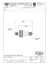 T & S Brass & Bronze Works B-0452 Datasheet
-
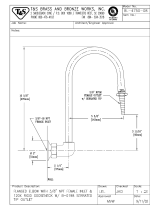 T & S Brass & Bronze Works BL-4750-08 Datasheet
-
T & S Brass & Bronze Works HG-4F-12 Datasheet
-
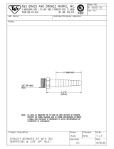 T & S Brass & Bronze Works BL-5550-25 Datasheet
-
T & S Brass & Bronze Works HG-2E-24 Datasheet
-
Harbor Freight Tools Item 62380 Quick start guide
-
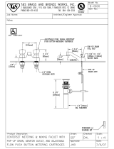 T & S Brass & Bronze Works B-0830 Datasheet
-
 T & S Brass & Bronze Works BL-4520-02 Datasheet
-
 T & S Brass & Bronze Works B-1413 Datasheet
-
 T'nB PVMF5 Datasheet


