Page is loading ...

Operator's Manual No. 1/2014 "Mobile Access Platform type Alulift M"
June 2014 Page 1
Operator's Manual
MOBILE ACCESS PLATFORM
TYPE Alulift M
(Original Manual)

Operator's Manual No. 1/2014 "Mobile Access Platform type Alulift M"
June 2014 Page 2
Table of Contents
1. GENERAL INFORMATION ............................................................................................................................. 5
1.1. Manufacturer ................................................................................................................................................... 5
1.2. Machinery Marking ....................................................................................................................................... 5
1.3. Definitions ........................................................................................................................................................ 5
1.4. Safety Symbols Used in this Manual ........................................................................................................ 5
1.5. National Requirements ................................................................................................................................ 6
1.6. Sample Declaration of Conformity ........................................................................................................... 7
2. TECHNICAL DATA ........................................................................................................................................... 8
2.1. Use of PRP type Alulift M for the Intended Purpose .......................................................................... 8
2.2. Failure to Use PRP type Alulift M for the Intended Purpose .......................................................... 8
3. DESCRIPTION OF THE PRP CONSTRUCTION AND OPERATION AND ADJUSTMENT OF
SAFETY COMPONENTS .................................................................................................................................. 9
3.2. List of Components Necessary for PRP type Alulift M Assembly ............................................... 11
4. DESCRIPTION OF THE DRIVE SYSTEM CONSTRUCTION, OPERATION AND ADJUSTMENT 12
4.1 Drive Unit ....................................................................................................................................................... 12
4.2 Service Brake ................................................................................................................................................ 12
4.3 Emergency Brake – Emergency Gripper ............................................................................................. 13
4.4 Control Pendant ........................................................................................................................................... 13
4.5 Audio Alarms. ............................................................................................................................................... 13
4.6 Wheel Brakes ................................................................................................................................................ 13
4.7 Safety System to Prevent Platform Overloading .............................................................................. 13
4.8 Drive Operating Time Meter ................................................................................................................... 14
4.9 Battery Charger ........................................................................................................................................... 14
5. ASSEMBLY AND DISASSEMBLY INSTRUCTIONS................................................................................ 14
5.1. Assembly ........................................................................................................................................................ 15
5.2. Conditions of Stability - Variants of Stabilizers ................................................................................ 21
5.3. PRP type Alulift M Anchoring Instruction .......................................................................................... 21
5.4. Disassembly .................................................................................................................................................. 22
5.5. Battery Disassembly .................................................................................................................................. 23
6. OPERATOR'S MANUAL ............................................................................................................................... 23
6.1. Control via Control Pendant .................................................................................................................... 24
6.2. Operator's Working Station ..................................................................................................................... 24
6.3. Operator's Qualifications .......................................................................................................................... 24
6.4. PRP Handling ................................................................................................................................................ 24

Operator's Manual No. 1/2014 "Mobile Access Platform type Alulift M"
June 2014 Page 3
6.5. Troubleshooting .......................................................................................................................................... 24
7. HAZARDS IDENTIFICATION AND RESIDUAL RISK INFORMATION ............................................ 25
8. SAFETY GUIDELINES. ................................................................................................................................. 26
8.1. Lighting ........................................................................................................................................................... 27
9. MAINTENANCE INSTRUCTIONS .............................................................................................................. 27
9.1. Maintenance Operator .............................................................................................................................. 27
9.2. Maintenance and Inspection Schedule ................................................................................................ 27
9.3. Pre-Assembly Reviews ............................................................................................................................. 28
9.4. Maintenance Reviews. ............................................................................................................................... 28
9.5. Ad hoc and Service Reviews. ................................................................................................................... 28
10. CRITERIA FOR COMPONENTS REPLACEMENT .................................................................................. 29
11. STORAGE AND TRANSPORT .................................................................................................................... 29
12. SAFETY SIGNS USED ON THE PRODUCT .............................................................................................. 30
13. GUARANTEE AND WARRANTY……………………................…………………………………………………….....32
14. APPENDIX No. 1…………………………....………………………………………………………………………...………..34
15. APPENDIX No. 2…………………………….......……………………………………………………………………………..35

Operator's Manual No. 1/2014 "Mobile Access Platform type Alulift M"
June 2014 Page 4
Foreword
We would like to inform you that Mobile Access Platform type Alulift M has passed a detailed EC
type examination carried out by the certification body JOAiCW TEST Sp. z o.o. [Ltd] .
The confirmation of the positive result of the inspection carried out by JOAiCW TEST Sp z o.o. is the
Inspection Certificate of the type issued.
Lockhard Sp. z o.o. [Ltd] is the only manufacturer of the Mobile Access Platform (Polish: PRP) type
Alulift M with a mobile work platform.
The Operator's Manual is considered to be a fundamental part of the Mobile Access Platform type
Alulift M. It contains necessary information on the assembly, disassembly and operation of the
device as well as users' work safety and how to maintain its efficiency.
Full and legible user's manual must be available at all times. "Mobile Access Platform type Alulift M"
will be hereinafter abbreviated as "PRP".
In order to avoid unnecessary damage and risks, the operator's responsibility is to read,
understand and obey this Operator's Manual
In addition to the PRP's Operator's Manual, general legal provisions and regulations for accident
prevention and environmental protection in force in the user's country shall apply.
You should refer to all the national and local rules for operating PRP type Alulift M on site.
LOCKHARD is not liable for any damage resulting from failure to
comply with this Manual.
Risk in this respect shall be borne by the user.

Operator's Manual No. 1/2014 "Mobile Access Platform type Alulift M"
June 2014 Page 5
1. GENERAL INFORMATION
1.1. Manufacturer
LOCKHARD Sp. z o.o.
Gorzyce Wielkie ul. Ostrowska 74a
63-410 Ostrów Wielkopolski
Tel. +48 627347129
e-mail: office@lockhard.eu
www.lockhard.eu
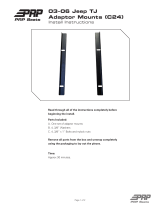
1.2. Machinery Marking
1.3. Definitions
Mobile Access Platform (PRP) - is a mobile machine intended to move persons to working
positions on which they carry out work from the work platform, on the assumption that these
persons enter the platform and exit the platform in its lower access position, which consists of
the work platform with controls, a load-bearing structure, a wheel assembly.
Work platform - a part of the mobile platform, a platform with railings, which can be moved
under load to a desired working position, and from which you can perform installations, repairs,
inspections or similar works.
Operator - a designated person, suitably trained to work at heights, entitled on the basis of
knowledge and practical experience and equipped with the necessary instructions for working
with the PRP.
Safe working load - the maximum weight carried by the work platform provided for in the
draft by the manufacturer. The safe working load comprises the weight of persons, tools and
materials.
1.4. Safety Symbols Used in this Manual
In order to draw your attention to the areas in this Manual which contain important information or
indicate danger, the following symbols are used. Special attention should be paid to areas marked
with these symbols as you study the instructions for use.
Lockhard Sp. z o.o.
Gorzyce Wielkie ul.Ostrowska 74a
63-410 Ostrów Wielkopolski
POLAND
Product:
Mobile Access Platform type Alulift M
Alulift Type: M
Weight: 55 kg – 475 kg
Safe working load: 250 kg
Voltage: 24V DC
Platform dimensions:
660x2400mm
Engine power: 600 W
Lift height: 12 m
Serial number: xxx
Platform speed:10 m/min
Year of manufacture: 2014

Operator's Manual No. 1/2014 "Mobile Access Platform type Alulift M"
June 2014 Page 6
Danger
This symbol indicates an immediate threat to people's life and health.
Failure to comply may result in a risk to life or a risk of serious injury and a
significant property damage.
Caution
It is a warning against possible damage to PRP or other things, if the action
marked in this way is performed incorrectly.
1.5. National Requirements
In addition to this Operator's Manual, attention should be given to the need to know and comply
with the generally applicable national and local laws and other binding regulations relating to work
safety and environmental protection in the country where the machine is used.
In the Republic of Poland "Mobile Access Platform type Alulift M" serving as a device for the
movement of persons and loads is a device qualifying for handling equipment and is subject to
technical supervision. It is the user's responsibility to report the PRP to UDT [Polish Office of
Technical Inspection].
Legal basis:
Regulation of the Council of Ministers of 7 December 2012 on types of technical devices subject to
technical inspection (Official Journal of Laws 2012 No. 0, item 1468), issued pursuant to Article 5,
paragraph 2 of the Law on technical inspection.

Operator's Manual No. 1/2014 "Mobile Access Platform type Alulift M"
June 2014 Page 7
1.6. Sample Declaration of Conformity
EC DECLARATION OF CONFORMITY
Manufacturer: LOCKHARD Sp. z o.o.
Gorzyce Wielkie ul. Ostrowska 74a
63-410 Ostrów Wielkopolski
Product: "Mobile Access Platform type Alulift M"
Serial number: XXX/20XX
Declare under our sole responsibility that the product referred to above fulfils the essential health
and safety requirements of the Directive 2006/42/EC OF THE EUROPEAN PARLIAMENT AND OF
THE COUNCIL under the harmonized standards:
PN-EN 1808+A1:2010
(EN 1808:1999+A1:2010)
item: 1, 2, 3.5, 3.6, 3.8, 3.9, 4,
5, 6, 7, 8.1, 8.3.1, 8.3.2, 8.3.5,
8.9.1, 9.1.2, 9.1.4, 9.1.8, 11.1 –
11.6, 12, 13, 14, Annex A,
Annex B
PN-EN 280:2013-11
(EN 280:2013)
item: 4, 5.5.5, 5.7, 5.8, 6, 7
PN-EN 12100:2012
(EN 12100:2012)
other standards:
PN-EN 1004:2005
(EN 1004:2004)
item: 1, 2, 3, 4, 7.1 – 7.5, 7.7,
7.8, 8.3, 8.3.2.1, 8.3.2.2, 8.4. 9,
10, 11, 12, 13, Annex A
PN-EN 12810-1:2010
(EN 12810-1:2003)
item: 6.2.3, 8.2, 8.3, 8.5.2
PN-EN 12811-1:2010
(EN 12810-1:2003)
item: 4.2.2, 6.2.7, 6.2.9.2
The EC type examination was carried out by the notified body JOAiCW Test Sp. z o. o., number
NB2057, 41-103 Siemianowice Śl. ul. Wyzwolenia 14, which issued the CE Examination
Certificate No. TEST/9/MD2014
The Product carries the mark:
2057
The technical documentation is stored at:
LOCKHARD Sp. z o.o.
Gorzyce Wielkie ul. Ostrowska 74a
63-410 Ostrów Wielkopolski
Gorzyce Wielkie, dated …………….
Technical Manager:
Łukasz Leonhard
……………………………………………
……...

Operator's Manual No. 1/2014 "Mobile Access Platform type Alulift M"
June 2014 Page 8
2. TECHNICAL DATA
Safe working load
250 kg (2 persons, tools and materials)
Work platform dimensions
660x2400 mm
Maximum platform lifting
and lowering speed
10 m/min (at full battery power)
Maximum height
12 m
Maximum PRP weight
approx. 475 kg
Supplied voltage
24 VDC
Engine power
600 W
Maximum drive motor speed
3000 rpm.
Transmission ratio
1:100
Battery capacity
33 Ah
Battery voltage
2x12 V
Operating temperature
-15° C up to +40 ° C
Noise
does not exceed 70 dB
c) load exerted by PRP on its setting and on the structure design, according to:
PN- EN 12811 clause 8 c
2.1. Use of PRP type Alulift M for the Intended Purpose
"Mobile Access Platform type ALULIFT M" is a mobile machine intended to move persons to
working positions on which they carry out work from the work platform, on the assumption that
these persons enter the platform and exit the platform in its one lower access position. "Mobile
Access Platform type ALULIFT M" consists of the work platform with controls, a load-bearing
structure and a wheel assembly.
"Mobile Access Platform type Alulift M" can be used indoors and outdoors.
2.2. Failure to Use PRP type Alulift M for the Intended Purpose
It is prohibited to use the PRP as a crane.
It is prohibited to use and move the PRPP when wind speed exceeds (12m/s - 6 on the
Beaufort scale).
It is prohibited to use the PRP during a storm.
It is prohibited to move the PRP using any motor vehicles such as a car, forklift truck,
tractor, etc.
It is prohibited to use lifting devices (hand or mechanical winches) on the PRP.
Do not increase (obscure) the side surface of the PRP. Increasing the area exposedto the
wind will decrease machine stability.
It is prohibited to stand on the handrails, braces and stabilizers.
It is prohibited to tie rods (not for anchors) between the PRP and another structure
(buildings, other scaffolding, etc.).
It is prohibited to place any objects against the PRP structure during assembly and
operation.
Not more than 2 persons may stay on the PRP work platform.
It is prohibited to use a PRP that is not properly maintained and inspected or is not in good
technical condition.

Operator's Manual No. 1/2014 "Mobile Access Platform type Alulift M"
June 2014 Page 9
3. DESCRIPTION OF THE PRP CONSTRUCTION AND OPERATION AND ADJUSTMENT OF
SAFETY COMPONENTS
List of the "Mobile Access Platform type Alulift M" components
Each PRP component is marked with:
a) a symbol in order to identify the PRP system and its manufacturer.
b) a year of manufacture, with the last two digits being used.
Table 1
Item
No.
Component
marking
Component photo
Component
description
Weigh
t
[kg]
1.
PS/14
Platform with
drive system
55
2.
H264/14
Horizontal
handrail
6
3.
HO264/14
Handrail with
access gate
8,5
4.
TB264/14
Toe-boards
6,1
5.
H95/14
Side handrail
3.9
6.
FR95100/14
FG95100/14
Base frame (right
and left marked
with colours)
complete with
pin bolts.
Running profile
mounted on the
base frame
10.6
7.
DB264/14
Diagonal braces
2.85

Operator's Manual No. 1/2014 "Mobile Access Platform type Alulift M"
June 2014 Page 10
8.
HB264/14
Horizontal braces
2.70
9.
CC05/14
Control pendant
PKS-3/W05
0.5
10.
WHEEL125/14
Small wheel
61125 CB
1.2
11.
WHEEL200/14
Large wheel
61200 CB
5.3
12.
BAT33/14
Gel batteries
Bt-02-12
2x9,5
13.
CHA1131/14
Battery charger
BAT 1131
0.45
14.
STAB3000/14
Stabilizer
4.28
15.
RA15/14
Gear rack
16.
SPR20/14
Gear
17.
GRA25/14
Gripper
(emergency
brake)

Operator's Manual No. 1/2014 "Mobile Access Platform type Alulift M"
June 2014 Page 11
18.
BFK457/14
Service brake
BFK 457
19.
AN450/14
Anchor bolt
20.
LI10-60/14
Pin bolt
Safety guardrails are an integral part of the platform
Pin bolts are an integral part of the load-bearing structure
3.2. List of Components Necessary for PRP type Alulift M Assembly
Table 2
PRP height
2
m
3
m
4
m
5
m
6
m
7
m
8
m
9
m
10
m
11
m
12
m
Component name
Number of components (pcs)
Red structure frame
2
3
4
5
6
7
8
9
10
11
12
Green structure frame
2
3
4
5
6
7
8
9
10
11
12
Diagonal braces
4
6
8
10
12
14
16
18
20
22
24
Horizontal braces
2
2
2
2
2
2
2
2
2
2
2
Horizontal handrail
1
1
1
1
1
1
1
1
1
1
1
Handrail with access gate
1
1
1
1
1
1
1
1
1
1
1
Side handrail
2
2
2
2
2
2
2
2
2
2
2
Wooden toe-board
2
2
2
2
2
2
2
2
2
2
2
Stabilizer
-
-
4
4
4
4
4
4
4
4
4
Small wheel
4
4
4
4
4
4
4
4
4
4
4
Large wheel
4
4
4
4
4
4
4
4
4
4
4
Battery
2
2
2
2
2
2
2
2
2
2
2
Platform
1
1
1
1
1
1
1
1
1
1
1
Total weight in kg
192
218
262
292
315
342
368
395
420
448
475

Operator's Manual No. 1/2014 "Mobile Access Platform type Alulift M"
June 2014 Page 12
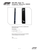
Fig. 1 Main PRP components
4. DESCRIPTION OF THE DRIVE SYSTEM CONSTRUCTION, OPERATION AND ADJUSTMENT
4.1 Drive Unit
The drive system in the PRP type Alulift M is an electric motor with 24 V, 600 W and 3000 rpm
speed. It is permanently attached to the CM063 type worm gear of 100 to 1 ratio. The worm
gear output rotational speed is 30 rpm. The drive system power is 114 Nm. A drive shaft fi 25 is
mounted on the worm gear, by which the device driving force is transferred to two extreme
ends of the shaft, where gears are mounted. The gears are splined to the gear rack located in the
vertical structure of the device. Upon starting the drive, the drive shaft is moved by the worm
gear. The rotary motion of the shaft makes the gear rotate, which enables vertical movement of
the platform.
4.2 Service Brake
The service brake system is composed of:
The INTORQ BFK457-08 COMPAKT type brake of rated voltage 24V, rated power 25 watt
and nominal braking torque 12 Nm.
CM 050 transmission of 1 to 10 ratio

Operator's Manual No. 1/2014 "Mobile Access Platform type Alulift M"
June 2014 Page 13
The service brake has nominal braking torque of 120 Nm, which is sufficient to brake and
maintain a work platform with safe working load of 250 kg. The service brake is an
electromagnetic brake which automatically starts the braking process at the time of control
circuit interruption - power supply loss.
The braking process is carried out using springs pressing the brake pads on the discs. Brake
release occurs at the time voltage is supplied to the solenoid coil.
4.3 Emergency Brake - Emergency Gripper
The emergency brake is made up of two independent grippers which make the platform stop if
the lowering speed exceeds 0.5 m/s. The emergency gripper is triggered by centrifugal switches
forming an integral part of the gripper.
If the gripper and the emergency brake are triggered on the platform, it is necessary to replace
the emergency brake system, which gets damaged during the platform stop, and which does not
allow its further operation; in this case you should notify the manufacturer or an authorized
service point in order to have the grippers replaced. Note - the gripper can be right-side and left-
side.
4.4 Control Pendant
Mobile Access Platform type Alulift M is able to move vertically up and down. In order to start the
drive which makes the platform move, the control pendant is used. There are three control
buttons on the control pendant. The emergency stop button is a master control button that is used
is to disconnect control in the other two buttons. This button has a built-in continuous control
system disconnection through key locking. The other two buttons located on the control pendant
are used to make the mobile platform move vertically UP and DOWN. These buttons are marked
by arrows and arranged by logical operation on the control pendant.
Photo: Control pendant
4.5 Audio Alarms.
The advance signal - before starting the platform a 5-second audio alarm is triggered
indicating that the platform is going to be started.
The operation signal - emitted while the platform is moving, which warns of possible
trapping, drawing-in or crushing.
4.6 Wheel Brakes
Wheel brakes are mechanical devices preventing the PRP from uncontrolled movements
during operation or stopping.
4.7 Safety System to Prevent Platform Overloading
The PRP is equipped with safety devices to protect the drive from overloading due to
platform overloading or blocking during upward movement. The overload protector

Operator's Manual No. 1/2014 "Mobile Access Platform type Alulift M"
June 2014 Page 14
protects the drive motor during upward movement, and the redundant protector protects
the circuit current of the drive motor and brake.
4.8 Drive Operating Time Meter
The drive operating time meter is located under the platform. The drive operating time
meter records and indicates the number of the PRP drive operating hours. In order to
ensure proper meter functioning you should check its status before and after operation.
4.9 Battery Charger
The PRP drive is supplied with a set of two batteries. A special device is provided for
charging the PRP drive gel batteries.
In order to connect the batteries to the charger, you should remove the batteries from the
battery chamber on the PRP platform.
5. ASSEMBLY AND DISASSEMBLY INSTRUCTIONS
Below is the description of the procedure for assembling and disassembling the "Mobile Access
Platform type Alulift M" produced by Lockhard Sp. z o.o.
Assembly, disassembly, operation and maintenance of the PRP may only be performed by properly
trained personnel, who must read and fully understand the following procedures and descriptions
before attempting to assemble or disassemble.
Two persons are required for assembly and disassembly. The area of the PRP assembly and
operation must be protected against unauthorized access by third parties.
Pre-assembly works
Before you begin the PRP assembly, check all the elements and components listed in
Table No. 2, which are necessary for its proper functioning, in particular the gear racks
and drive gears as well as the emergency gripping equipment.
For assembly, use only undamaged and original manufacturer's parts.
Before commencing the PRP type Alulift M assembly, check the surrounding area for safety, eg. if
there are no electrical installations, ruins, rubble, excavations, mobile cranes, pedestrian traffic, any
vehicle or machine traffic, etc. in the area.
If there is a risk of coming into contact with overhead electrical power lines, these lines should be
shut off.
Electrical power lines which are in the distance of the level of free-swinging extreme cables from
the furthest possible outer edge of the transferred elements at the time of PRP operation, assembly
and disassembly do not require being shut off, with the said distance being not closer than:
2 m for a low voltage line of 400V
5 m for a line of up to 15 kV
10 m for a line of up to 30 kV
15.0 m for a line of over 30 kV
You should check the ground on which PRP will be installed. The ground must be horizontal and
hardened.

Operator's Manual No. 1/2014 "Mobile Access Platform type Alulift M"
June 2014 Page 15
5.1. Assembly
The structure of the PRP provides for quick assembly without the use of tools.
Stage I - platform assembly
The PRP platform should be placed on the destination assembly location.
Photo 1 Photo 2
First, you must install the required guardrails on the platform.
Photo 3 Photo 4
Connect side handrails to the horizontal handrail and build the handrail with access gate
Photo 5 Photo 6
Install toe-boards
Photo 7 Photo 8

Operator's Manual No. 1/2014 "Mobile Access Platform type Alulift M"
June 2014 Page 16
Remove the covers protecting the gears and the roller guides of the drive system
Photo 9 Photo 10
Install the battery in the battery bay under the platform and connect the power supply cables
Stage II - load-bearing structure assembly
Put the frames of the load-bearing structure with the roller guides on the appropriate sides of
the mobile platform, in accordance with the markings - colour-coded green and red,
Photo 11 Photo 12
Photo 13 Photo 14
Photo 15 Photo 16
Using the key unlock the emergency stop button on the control pendant. Before pressing the
control pendant buttons, make sure that it is held securely.

Operator's Manual No. 1/2014 "Mobile Access Platform type Alulift M"
June 2014 Page 17
Photo 17 Photo 18
Press and hold the white button on the control pendant until the platform is lifted 2 - 10 cm
upwards
PRP Alulift M will work properly as long as the gears and the gear racks
simultaneously engage on both sides of the load-bearing structure!
Install two (shorter) horizontal braces connecting PRP base frames
Install diagonal braces connecting PRP base frames on the opposite side of the access gate.
Install one end of the brace on the lowest level of the first segment of the base frame. Install the
other end of the brace on the highest level of the opposite side of the first segment.
Photo 19 Photo 20
The brace hooks should be fitted in the designated places.
Correct position of fitting braces.

Operator's Manual No. 1/2014 "Mobile Access Platform type Alulift M"
June 2014 Page 18
Level the equipment using aligning bolts in the wheels and lock the wheels using a brake at each
of the four wheels and check the levelness of the platform using a bubble level.
Photo 21 Photo 22
Stage III further structure levels assembly
From the ground fit further matching frames of the PRP load-bearing structure. (please pay
attention to the colour marking scheme of the components - red and green)
Photo 23 Photo 24
View of the base frames and mobile platform marking.
Each time after connecting base frames of the structure, secure them by
pin bolts in order to prevent their unintended retracting.
Photo 25 Photo 26
Insert pin bolts in the holes in the pillars of the frame structure. Install diagonal braces
connecting PRP base frames.
Install one end of the brace on the lowest level of the base frame. Install the other end of the
brace on the highest level of the opposite side. The correct braces assembly is shown in the
photograph No. 26.
When building the next level, the following should be loaded on the platform:
The red-marked base frame
The green-marked base frame
Two diagonal braces

Operator's Manual No. 1/2014 "Mobile Access Platform type Alulift M"
June 2014 Page 19
While the PRP platform is moving, it is important to remember that all of the
transported components must not protrude beyond the outline of the platform
railings.
Operation may start only if the platform handrails are properly locked to prevent accidental fall.
Move the platform to the most suitable place in order to be able to install the third segment.
Photo 27
Install further frames of the load-bearing structure by matching them according to the colour
marking scheme.
Photo 28 Photo 29
Install diagonal braces connecting PRP base frames. Install one end of the brace on the lowest
level of the third segment of the base frame. Install the other end of the brace on the highest
level of the opposite side of the third segment.
Photo 30
Before commencing the fourth level assembly, four stabilisers should be fitted by screwing them
with radial grips down to the base frame of the structure.
After fitting the stabilizers, check if the stabilizer bars rigidly adjoin the ground in order to make
sure that they are fitted correctly.

Operator's Manual No. 1/2014 "Mobile Access Platform type Alulift M"
June 2014 Page 20
When applying large force, the stabilizer should not move in lateral direction - rotation and
vertical.
Photo 31 Photo 32
Photo 33
Photo 34
After fitting the stabilizers, you can proceed to install the fifth and any further level, according to
the instructions of Stage III.
Subsequent phases of fitting
stabilizers
View of the assembled platform type ALULIFT M
/