Page is loading ...

P/N 3771301, Rev. A [6/2011]
USER'S
INFORMATION
MANUAL
Information and specifi cations outlined in this manual in effect at the
time of printing of this manual. ECR International reserves the right to
discontinue, change specifi cations or system design at any time without
notice and without incurring any obligation, whatsoever.
Check our website frequently for updates: www.ecrinternational.com
SERIES
USC
GAS FIRED HOT WATER HEATING BOILER
WARNING: If the information in this manual is not
followed exactly, a fi re or explosion may result causing
property damage, personal injury or loss of life.
Do not store or use gasoline or other fl ammable
vapors and liquids in the vicinity of this or any
other appliance.
WHAT TO DO IF YOU SMELL GAS
Do not try to light any appliance.•
Do not touch any electrical switch; do not use •
any phone in your building.
Immediately call your gas supplier from a •
neighbor's phone. Follow the gas supplier's
instructions.
If you cannot reach your gas supplier, call the •
fi re department.
Installation and service must be performed by a
qualifi ed installer, service agency or the gas
supplier.
Do not use this boiler if any part has been under water. Immediately call a qualifi ed service technician to
inspect the boiler and to replace any part of the control system and any gas control which has been under
water.
Should overheating occur or the gas supply fail to shut off, do not turn off or disconnect the electrical supply to
the pump. Instead, shut off the gas supply at a location external to the appliance.
Utica Boilers
2210 Dwyer Avenue,
Utica NY 13504-4729

2
USERS INFORMATION MANUAL
INSTRUCTIONS FOR OPERATION AND MAINTENANCE
OF GAS FIRED HOT WATER HEATING BOILER
RETAIN FOR FUTURE REFERENCE
SAFETY SYMBOLS & WARNINGS
The following defi ned symbols are used throughout this
manual to notify the reader of potential hazards of varying
risk levels.
DANGER
!
DANGER
Indicates a hazardous situation which, if not
avoided, WILL result in death or serious injury.
NOTICE
Indicates information which should be followed to
ensure proper installation and operation.
!
WARNING
Indicates a hazardous situation which, if not
avoided, could result in death or serious injury.
!
CAUTION
Indicates a hazardous situation which, if not avoid-
ed, may result in minor or moderate injury.
Utica Boilers recommends all boiler maintenance be
performed by a trained heating technician.
Before any procedures are attempted on this appliance, it
is necessary to determine if the ignition system is a electric
or standing pilot system. If you are uncertain, contact the
manufacturer before proceeding.

3
LIGHTING INSTRUCTIONS
!
WARNING
Before lighting any type of pilot burner (standing
or intermittent), make certain the hot water boiler
and system are full of water to minimum pressure
of 12 psi in the system, and also make certain that
the system is vented of air. Refer to the following
appropriate lighting instruction.
LIGHTING PROCEDURE FOR BOILER WITH
INTERMITTENT PILOT SYSTEM
!
WARNING
If you do not follow these instructions exactly,
a fi re or explosion may result causing property
damage, personal injury or loss of life.
This appliance is equipped with an ignition device which A.
automatically lights the pilot. Do not try to light the
appliance by hand.
Before operating, smell all around the appliance area B.
for gas. Be sure to smell next to the fl oor because
some gas is heavier than air and will settle on the fl oor.
Read "What To Do If You Smell Gas" on front page of
this manual.
Use only your hand to move ignition system control C.
switch. Never use tools. If the switch will not move
by hand, don’t try to repair it, call a qualifi ed service
technician. Force or attempted repair may result in a
fi re or explosion.
Do not use this appliance if any part has been under D.
water. Immediately call a qualifi ed service technician
to inspect the appliance and to replace any part of the
control system and any gas control which has been
under water.
E.
F.
OPERATING INSTRUCTIONS FOR INTERMITTENT
PILOT SYSTEM
STOP!
1.
Read safety information above.
Set thermostat to lowest setting.
2.
Turn off all electric power to
3.
appliance.
This appliance is equipped with ignition device which
4.
automatically lights the pilot. Do not try to light pilot by
hand.
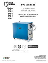
Move ignition control switch to “OFF.” See fi gure 1.
5.
Wait (5) minutes to clear out any gas. If you then smell
6.
gas, STOP! Follow “What To Do If You Smell Gas” on
front cover of this manual. If you don’t smell gas, go on
to the next step.
Move ignition control switch to “ON.”
7.
Turn on all electric power to appliance.
8.
Set thermostat to desired setting.
9.
If appliance will not operate, follow instructions
10.
“To Turn Off Gas To Appliance” on page 1 and call
qualifi ed service technician or your gas supplier.
Figure 1 - Intermittent Pilot

4
LIGHTING INSTRUCTIONS
To Turn Off Gas To Appliance
Set the thermostat to lowest setting.
1.
Turn off all electric power to the appliance if service is
2.
to be performed.
Move ignition system control switch to "OFF."
3.
Replace access panel.
4.
GENERAL INSTRUCTIONS
Before seasonal start-up, have a qualifi ed service agency
check boiler for soot and scale in fl ue passageways and
clean burners.
Venting system should also be inspected at start of each
heating season. Vent pipe from boiler should be checked for
signs of deterioration or sagging joints. Repair if necessary.
Following procedure should be followed to clean and check
fl ue gas passageways:
Turn off gas to boiler at manual gas valve.
1.
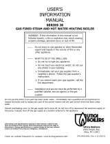
Remove jacket front panel. See fi gure 2.
2.
Disconnect vent pipe from vent adapter.
3.
Disconnect air inlet pipe from coupling. See fi gure 5.
4.
Remove air box covers. See fi gure 5.
5.
Remove burners from combustion chamber by raising
6.
burners up from manifold orifi ces and pulling toward
front of boiler. See fi gure 3.
Remove top panel. See fi gure 2
7.
.
Remove fl ue collector and venter assembly from boiler
8.
castings by removing hold-down screws located on
each side of fl ue collector. See fi gure 4.
Figure 2 - Front Jacket Panel
Figure 3 - Gas Burner Tubes

5
GENERAL INSTRUCTIONS
Remove baffl es from heat exchanger. See fi gure 5.
9.
Visually inspect baffl es for any unusual wear or soot
10.
build up.
Visually inspect venter assembly for any unusual wear
11.
or dirt build up.
Place sheet of heavy paper or similar material in
12.
bottom of combustion chamber and brush down fl ue
passageways. Soot and scale will collect on paper and
is easily removed with paper.
Replace Flue Collector using hold down screws and
13.
silicone in place with GE IS 808 silicone. See fi gure 4.
Execute
14.
steps 1-9 in reverse order to reassemble
boiler.
Figure 4 - Flue Collector
Figure 5 - Heat Exchanger

6
GENERAL INSTRUCTIONS
V• isual check of main burner and pilot fl ames should be
made at start of the heating season and again in mid-
season.
M• ain burner fl ame should have well defi ned inner blue
mantel with lighter blue outer mantel. If fl ame does
not appear this way, check burner throats and burner
orifi ces for lint or dust obstructions. See fi gure 6.
P• ilot fl ame should envelop 3/8 to 1/2 inch of tip of
ignition electrode. To adjust pilot fl ame, remove
pilot adjustment cover screw on gas valve and
turn inner
screw clockwise
to decrease or
counterclockwise
to increase pilot fl ame.
Replace cover screw after adjustment to prevent
possible gas leakage. (See fi gures 1, 7 & 8 below.)
Check b• urners and pilot for signs of corrosion, rust or
scale buildup. Clean with nylon bristle brush.
Keep• area around boiler clear and free of combustible
materials, gasoline and other fl ammable vapors and
liquids.
F• ree fl ow of combustion and ventilating air to boiler and
boiler room must not be restricted or blocked.
In event fl ow of combustion products through fl ueways •
or boiler venting system becomes blocked, pressure
switch or ignition system will shut off main burner gas.
If this condition occurs, do not attempt to place boiler in
operation. Contact qualifi ed service agency.
Annual inspection of boiler and heating system •
should be done by qualifi ed service agency. They are
experienced in making inspection outlined above and
in event repairs or corrections are necessary, they can
make proper changes for safe operation of boiler.
Figure 7 - Pilot Flame
Figure 6 - Main Burner Flame

7
Date Service Performed Company Name & Tech Initials Company Address & Phone #
NOTES AND SERVICE RECORD

An ISO 9001-2008 Certifi ed Company
ECR International, Inc.
2201 Dwyer Ave.
Utica, NY 13501
Utica Boilers
2201 Dwyer Ave, Utica, NY 13501
Date of Installation:
Boiler Model #:
Installed By:
/