Page is loading ...

P/N 240009268, Rev. D [10/2014]
MGC SERIES
GAS-FIRED
HOT WATER BOILERS
INSTALLATION, OPERATION &
MAINTENANCE MANUAL
An ISO 9001-2008 Certified Company
Manufactured by:
ECR International, Inc.
2201 Dwyer Avenue, Utica NY 13501
web site: www.ecrinternational.com
Models
MGC-8D
MGC-8DP
MGC-9D
MGC-9DP
C.S.A. Certied for
Natural gas or
Propane
Tested for 50 psi.
ASME Working
Pressure

2
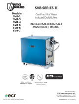
1 - DIMENSIONS
Table 1 - Dimensions
BOILER
MODEL
NUMBER
DIMENSIONS (INCH.)
FLUE
DIAMETER
“A”
WIDTH
MGC-8 7 27½
MGC-9 7 30¾
Add 5½” to height for vent Damper.
Figure 1 - Dimensions
* Minimum acceptable height for Low Water Cutoff probe.
*

3
2 - BOILER RATINGS AND CAPACITIES
Table 2 - Ratings and Capacities
BOILER
MODEL
NUMBER
(1)
† NATURAL GAS † PROPANE GAS AFUE
Input
(3)
Mbh
(1)
Heating
Capacity
(3)
Mbh
(2)
NET AHRI
RATING
Water,
(3)
Mbh
INPUT
(3)
MBH
HEATING
CAPACITY
(3)
MBH
NET AHRI
RATING
INTERMITTENT
IGNITION WITH
VENT DAMPER
MGC-8 262.5 220 191 245 206 179 83.9
MGC-9 299 251 218 280 235 204 83.7
†
Input rating for sea level to 2,000 ft. (610m) above sea level.
Over 2000 ft (610m) above sea level.
Reduce input rate 4% for every 1000 ft (304m) above sea level.
+ Heating Capacity based on D.O.E. (Department of Energy) test procedure.
(1)
Add model number sufce ‘P’ for Propane.
(2)
Net AHRI Water rating shown based on piping and pickup allowance of 1.15. Consult manufacturer before selecting
boiler for installations having unusual piping and pickup requirements, such as intermittent system operation,
extensive piping systems, etc.
(3)
MBH = 1,000 Btuh = British Thermal Unit Per Hour
Ratings marked “Net AHRI Ratings” indicate amount of remaining heat input used to heat radiation or terminal units. Net
AHRI Ratings shown are based on allowance of 1.15 in accordance with factors shown on AHRI Standard as published by
The Hydronics Institute.
- Selection of boiler size should be based upon “Net AHRI Rating” being equal to or greater than calculated heat loss of the
building.
- Consult manufacturer before selecting boiler for installations having unusual piping and pickup requirements.
BOILERS FOR USE AT HIGH ALTITUDE
Boiler is factory equipped for use at altitudes of 0-2,000 feet above sea level.
For use at altitudes above 2,000 feet above sea level, input ratings are reduced by change in main burner orice size.
For altitudes above 2,000 feet above sea level, input ratings should be reduced at rate of 4% for each 1,000 feet above
sea level. Consult National Fuel Gas Code, ANSI Z223.1/NFPA 54 or manufacturer for correct orice sizing information.

4
3 - TABLE OF CONTENTS
IMPORTANT: Read the following instructions
COMPLETELY before installing!!
KEEP THIS MANUAL NEAR BOILER
RETAIN FOR FUTURE REFERENCE
WARNING
Keep boiler area clear and free from
combustible materials, gasoline and other
ammable vapors and liquids.
DO NOT obstruct air openings to the boiler
room.
Modication, substitution or elimination
of factory equipped, supplied or specied
components may result in personal injury or
loss of life.
TO THE OWNER - Installation and service of
this boiler must be performed by a qualied
installer.
TO THE INSTALLER - Leave all instructions
with boiler for future reference.
When this product is installed in the
Commonwealth of Massachusetts the
installation must be performed by a Licensed
Plumber or Licensed Gas Fitter.
!
WARNING
Fire, explosion, asphyxiation and electrical
shock hazard. Improper installation could
result in death or serious injury. Read this
manual and understand all requirements
before beginning installation.
!
SAFETY SYMBOLS & WARNINGS
The following dened symbols are used throughout
this manual to notify the reader of potential hazards
of varying risk levels.
NOTICE
Used to address practices not related to
personal injury.
CAUTION
Indicates a hazardous situation which, if not
avoided, could result in minor or moderate
injury.
!
WARNING
Indicates a hazardous situation which, if not
avoided, could result in death or serious injury.
!
DANGER
Indicates a hazardous situation which, if not
avoided, WILL result in death or serious injury
!
1 - Dimensions ....................................................2
2 - Ratings And Capacities ....................................3
3 - Table of Contents ............................................4
4 - Installation Procedure .....................................5
5 - Ventilation & Combustion Air ............................ 6
6 - Connecting Supply And Return Piping ................7
7 - Chimney And Vent Pipe Connection ................. 11
8 - Vent Damper Operation ................................. 14
9 - Gas Supply Piping ......................................... 15
10 - Electrical Wiring .......................................... 15
11 - Wiring Diagrams ......................................... 16
12 - General Instructions .................................... 19
13 - Lighting Instructions ................................... 20
14 - Operating Your Boiler .................................. 21
15 - Maintaining Your Boiler ................................ 23
16 - Service Hints .............................................. 24
17 - Equipment And Optional Accessories ............ 25
Appendix A - Control Module ............................... 27

5
4 - INSTALLATION PROCEDURE
Table 3 -
MINIMUM CLEARANCE DIMENSIONS
Inches (mm)
Top 6” (152mm)
Rear 6” (152mm)
Control Side 7” (178mm)
Opposite Side 6” (152mm)
Front
18” (457mm)
Flue/Vent Connector 6” (152mm)
Near Boiler Piping 2” (51mm)
WARNING
Improper installation, adjustment, alteration,
service or maintenance could result in death or
serious injury.
!
WARNING
Fire hazard. Do not install boiler on
combustible ooring or carpeting. Failure to
follow these instructions could result in death
or serious injury.
!
1.
FOR INSTALLATION ON NON-COMBUSTIBLE
FLOORS ONLY - For installation on combustible
ooring special base must be used. (See
Replacement Parts Section.) Boiler can not be
installed on carpeting.
NOTE: Greater clearances for access should supersede fire
protection clearances.
* Denition of Alcove is three sided space with no
wall in front of boiler. ANSI standard for alcove is 18
inches from front of appliance to leading edge of side
walls as shown below.
1.
Installation must conform to the requirements
of the authority having jurisdiction or, in the
absence of such requirements, to the National
Fuel Gas Code, ANSI Z223.1/NFPA 54.
2.
Where required by the authority having
jurisdiction, the installation must conform to the
Standard for Controls and Safety Devices for
Automatically red Boilers, ANSI/ASME CSD-1.
3.
Boiler series is classied as a Category I. Vent
installation shall be in accordance with "Venting of
Equipment ," of the National Fuel Gas Code, ANSI
Z223.1/NFPA 54 or applicable provisions of the
local building codes.
4.
Boiler has met safe lighting and other
performance criteria with the gas manifold and
control assembly on the boiler per the latest
revision of ANSI Z21.13/CGA 4.9.
5.
Install boiler such that gas ignition system
components are protected from water (dripping,
spraying, rain, etc.) during appliance operation
and service, (circulator replacement, condensate
trap, control replacement, etc.).
6.
Locate boiler on level, solid base as near chimney
as possible and centrally located with respect to
heat distribution system as practical.
7.
Allow 24 inches (610mm ) at front and right side
for servicing and cleaning.
8.
When installed in utility room, door should be
wide enough to allow largest boiler part to enter,
or to permit replacement of another appliance
such as water heater.
Minimum Clearances to Combustible
Construction (as seen from above)
6"
BOILER
18"
6"
Front
7"
Control
Side

6
5 - VENTILATION & COMBUSTION AIR
Provide combustion air and ventilation air in accordance
with the section “Air for Combustion and Ventilation,”
of the National Fuel Gas Code, ANSI Z223.1/NFPA 54 or
applicable provisions of local building codes.
Provide make-up air where exhaust fans, clothes
dryers, and kitchen ventilation equipment interfere
with proper operation.
National Fuel Gas Code recognizes several methods
of obtaining adequate ventilation and combustion air.
Requirements of the authority having jurisdiction may
override these methods.
• Engineered Installations. Must be approved by
authority having jurisdiction.
• Mechanical Air Supply. Provide minimum of
0.35 cfm per Mbh for all appliances located
within space. Additional requirements where
exhaust fans installed. Interlock each appliance
to mechanical air supply system to prevent main
burner operation when mechanical air supply
system not operating.
• All Indoor Air. Calculate minimum allowable room
volume for all appliances in space. Use a different
method if minimum volume not available.
A. Standard Method. Cannot be used if known
air inltration rate is less than 0.40 air
changes per hour. See Table 4 for space
with boiler only. Use equation for multiple
appliances.
Volume ≥ 50 ft
3
x Total Input [Mbh]
B. Known Air Inltration Rate. See Table 4
for space with boiler only. Use equation
for multiple appliances. Do not use an air
inltration rate (ACH) greater than 0.60.
Volume ≥
21 ft
3
⁄ACH x Total Input [Mbh]
C. Refer to National Fuel Gas Code for opening
requirements between connected indoor
spaces.
• All Outdoor Air. Provide permanent opening(s)
communicating directly or by ducts with outdoors.
A. Two Permanent Opening Method. Provide
opening commencing within 12 inches of top
and second opening commencing within 12
inches of bottom of enclosure.
Direct communication with outdoors or
communicating through vertical ducts.
Provide minimum free area of 1 in² per 4
Mbh of total input rating of all appliances
in enclosure.
Communicating through horizontal ducts.
Provide minimum free area of 1 in² per 2
Mbh of total input rating of all appliances
in enclosure.
B. One Permanent Opening Method. Provide
opening commencing within 12 inches of top
of enclosure. Provide minimum clearance of
1 inch on sides/back and 6 inches on front
of boiler (does not supersede clearance to
combustible materials).
• Refer to National Fuel Gas Code for additional
requirements for louvers, grilles, screens and air
ducts.
• Combination Indoor and Outdoor Air. Refer
to National Fuel Gas Code for application
information.
Table 4 - Minimum Room Volume, Indoor Air Only*
Room Cubic Feet Volume
Input
Mbh
Standard
Method
Known Air Inltration Rate Method (Air Changes Per Hour)
0.1 0.2 0.3 0.4 0.5 0.6
262.5 13125 55125 27563 18375 13781 11025 9188
299 14950 62790 31395 20930 15698 12558 10465
* Table values based on boiler only. Add volume for any additional appliances.

7
6 - CONNECTING SUPPLY AND RETURN PIPING
RELIEF VALVE
DISCHARGE
LINE
Check local
codes for
maximum
distance
from oor
or allowable
safe point of
discharge.
Figure 2 - Safety Relief Valve
1.
Refer to local codes and appropriate ASME Boiler
and Pressure Vessel Code for additional installa-
tion requirements. Install safety relief valve using
pipe ttings provided with boiler. See Figure 2
2.
Install safety relief valve with spindle in vertical
position.
3.
Do not install shutoff valve between boiler and
safety relief valve.
4.
Install discharge piping from safety relief valve.
See Figure 2.
• Use ¾” or larger pipe.
• Use pipe suitable for temperatures of 375°F
(191°C) or greater.
• Individual boiler discharge piping shall be inde-
pendent of other discharge piping.
• Size and arrange discharge piping to avoid
reducing safety relief valve relieving capacity
below minimum relief valve capacity stated on
rating plate.
• Run pipe as short and straight as possible to
location protecting user from scalding and prop-
erly drain piping.
• Install union, if used, close to safety relief valve
outlet.
• Install elbow(s), if used, close to safety relief
valve outlet and downstream of union (if used).
• Terminate pipe with plain end (not threaded).
WARNING
Burn and scald hazard. Safety relief valve
could discharge steam or hot water during
operation. Install discharge piping per these
instructions.
!

8
6 - CONNECTING SUPPLY AND RETURN PIPING
1.
Boiler is shipped assembled. Install discharge
piping from safety relief valve. See Warning, Page
7.
2.
Install temperature pressure gauge.
• Apply pipe sealant to threads on shaft of
gauge.
• Thread gauge into supply water tee. See Figure
3.
NOTICE
DO NOT TIGHTEN GAUGE BY HAND!! Gauge
should be tightened using crescent wrench or
9/16” open end wrench. See Figure 3.
3.
Connect supply and return lines to boiler.
Connections may require additional ttings and
parts, as shown on diagrams.
WARNING
Burn and scald hazard. Safety relief valve
could discharge steam or hot water during
operation. Install discharge piping per these
instructions.
!
Figure 3 - Temperature Pressure Gauge
Verify clean water supply is available to water inlet
valve. Install sand strainer when water supply is from
a well or pump.
Install hot water boiler above radiation level or as
required by Authority having jurisdiction. Install low
water cutoff device at time of installation. See Figure
1 for minimum probe height. Use kit #550002998.
Follow instruction enclosed with kit. With other
LWCO’s use their manufacturer specic instructions.
Periodic inspection is necessary, as is ushing of oat
type devices, per manufacturers specic instruction.
FOR USE WITH COOLING UNITS
A. Boiler used in connection with refrigeration
system, must be installed so that chilled medium
is piped in parallel with heating boiler. Appropriate
valves must be used to prevent chilled medium
from entering heating boiler. See Figure 5 page 9.
B. Boiler connected to heating coils located in air
handling units where they may be exposed to
refrigerated air circulation, piping system shall
be equipped with ow control valves or other
automatic means to prevent gravity circulation of
boiler water during cooling cycle.
LOW WATER TEMPERATURE AND LARGE WATER
CONTENT SYSTEM (See Figures 6 and 7, Page 10.)
Signicant condensation may form in boiler and/or
venting system if boiler is operated for long period of
time with return temperatures of less than 120° F.
Condensate is corrosive and can cause severe
damage to boiler and venting system. Minimum
design return water temperature to prevent
condensation in boiler and venting is 120°F.
Minimum high limit setting is 140°F.
1.
Boiler used in heating system where design
water temperatures below 140°F are desired
(e.g. radiant oor heating), 4-way mixing valve
or suitable alternative is required to prevent low
temperature return water from entering boiler.
Follow mixing valve manufacturer’s instructions.
2.
Boiler connected to system having large water
content (such as former gravity system), install
system bypass. See Figures 6 and 7, page 10.
3.
If boiler water reset control is used to operate
boiler, minimum reset supply water temperature
setpoint must be at least 140°F, unless mixing
valve is used as in (1) above.

9
Figure 5 - Chilled Water Piping
Figure 4 - Typical Hot Water Piping
6 - CONNECTING SUPPLY AND RETURN PIPING

10
Figure 6 - BYPASS PIPING - CIRCULATOR ON SUPPLY
Figure 7 - BYPASS PIPING - CIRCULATOR ON RETURN
Bypass Piping Required For High Mass (Large Water Content) Systems
6 - CONNECTING SUPPLY AND RETURN PIPING

11
Boilers connecting to gas vents or chimneys, vent
installations shall be in accordance with “Venting of
Equipment”, of the National Fuel Gas Code, ANSI
Z223.1/NFPA 54 or applicable provisions of the local
building codes.
Check Your Chimney
It must be clean, right size, properly constructed and
in good condition.
Chimney Sizing
Chimney sizing, and vent installation must be in
accordance with The National Fuel Gas Code, ANSI
Z223.1/NFPA 54 or applicable provisions of local
building codes.
This is a high efciency boiler with low stack
temperature. Following recommendations are in
addition to requirements of the National Fuel Gas
Code.
1. Type B double wall vent pipe is recommended for
vent connector. Single wall vent connectors should
not be used unless following conditions are true:
a) Except for basement, boiler is not installed in
unheated space.
b) Total horizontal portion of vent connector, not
including elbows is less than 5 feet in length.
2. Outside chimneys (i.e. chimneys exposed to
outdoors below roof line) should not be used unless
they are:
a) enclosed in a chase, or
b) lined with type B vent pipe, or listed exible
vent liner, or other certied chimney lining system.
3. Where possible it is recommended to common vent
boiler and water heater.
4. For multiple boiler installations, consult boiler
manufacturer for venting recommendations.
Connecting The Vent Damper And Vent
Connector
Refer to Figure 1, page 2 for size and location of vent
(ue opening).
NOTICE
Damper blade on furnished vent damper has
1/2 square inch hole (approximately 3/4”
diameter). Boilers equipped with intermittent
ignition, hole should be plugged by using plug
supplied with vent damper.
1.
Position furnished vent damper on top of ue
outlet collar. Fasten damper securely to ue
outlet collar with sheet metal screws. Verify
damper blade has clearance to operate inside of
diverter. Do not modify either draft diverter or
vent damper during installation.
As An Option
Damper may be installed in horizontal or vertical
position, closer to ue outlet collar preferred. See
Figures 8, 9 and 10 and enclosed vent damper
instructions.
2.
Install vent damper to service only single boiler
for which it is intended. Damper position indicator
shall be in visible location following installation.
Locate damper so it is accessible for servicing.
3.
Damper must be in the open position when
appliance main burners are operating.
4.
Boiler is equipped with factory wired harness that
plugs into vent damper.
5.
Slope pipe up from boiler to chimney not less
than 1/4” per foot.
6.
Run pipe as directly as possible with as few
elbows as possible.
7.
Do not connect to replace ue.
8.
End of vent pipe must be ush with inside face of
chimney ue. Use a sealed-in thimble for chimney
connection.
Fasten sections of vent pipe with sheet metal screws
to make piping rigid. Support horizontal potions of
vent system to prevent sagging. Use stovepipe wires
every 5’ to support pipe from above. Use double wall
vent pipe if vent pipe must go through crawl space.
Where vent pipe passes through combustible wall
or partition, use ventilated metal thimble. Thimble
should be 4 inches larger in diameter than vent p
7 - CHIMNEY AND VENT PIPE CONNECTION
WARNING
Boiler and venting installations shall be
performed by a qualied expert and in
accordance with the appropriate manual.
Installing or venting boiler or other gas
appliance with improper methods or materials
may result in serious injury or death due to
re or to asphyxiation from poisonous gases
such as carbon monoxide with is odorless and
invisible.
!

12
WARNING
Do not connect boiler to any portion of
mechanical draft system operating under
positive pressure.
!
Minimum Vent Pipe Clearance
Wood and other combustible materials must not be
closer than 6” from any surface of single wall metal
vent pipe. Listed Type B vent pipe or other listed
venting systems shall be installed in accordance with
their listing.
Removing Existing Boiler From Common
Venting System
When an existing boiler is removed from common
venting system, common venting system is likely to be
too large for proper venting of appliances remaining
connected to it.
At time of removal of existing boiler, following steps
shall be followed with each appliance remaining
connected to the common venting system placed
in operation, while other appliances remaining
connected to common venting system are not in
operation.
1.
Seal any unused openings in the common venting
system.
2.
Visually inspect the venting system for proper
size and horizontal pitch and determine there is
no blockage or restriction, leakage, corrosion and
other deciencies which could cause an unsafe
condition.
3.
Insofar as is practical, close all building doors
and windows and all doors between the space in
which the appliances remaining connected to the
common venting system are located and other
spaces of the building. Turn on clothes dryers
and any appliance not connected to the common
venting system. Turn on any exhaust fans, such
as range hoods and bathroom exhausts, so they
will operate at maximum speed. Do not operate a
summer exhaust fan. Close replace dampers.
7 - CHIMNEY AND VENT PIPE CONNECTION
4.
Place in operation the appliance being inspected.
Follow the lighting instructions. Adjust thermostat
so appliance will operate continuously.
5.
Test for spillage at the draft hood relief opening
after 5 minutes of main burner operation. Use
the ame of a match or candle, or smoke from a
cigarette, cigar or pipe.
6.
After it has been determined that each appliance
remaining connected to the common venting
system properly vents when tested as outlined
above, return doors, windows, exhaust fans,
replace dampers and any other gas-burning
appliance to their previous conditions of use.
7.
Any improper operation of the common venting
system should be corrected so the installation
conforms with the National Fuel gas Code, ANSI
Z223.1/NFPA 54. When re-sizing any portion of
the common venting system, the common venting
system should be re-sized to approach the
minimum size determined using the appropriate
tables in Chapter 13 of the National Fuel Gas
Code, ANSI Z223.1/NFPA 54.
WARNING
Boiler and venting installations shall be
performed by a qualied expert and in
accordance with the appropriate manual.
Installing or venting boiler or other gas
appliance with improper methods or materials
may result in serious injury or death due to
re or to asphyxiation from poisonous gases
such as carbon monoxide with is odorless and
invisible.
!

13
8 - VENT DAMPER OPERATION
Figure 8 - Vent Damper Installation Figure 9 - Vent Damper Placement
Annually check vent damper and all ue product
carrying areas of appliance, with particular attention
given to deterioration from corrosion or other
sources. If you see corrosion or other deterioration,
contact your heating contractor for repairs. Check
vent damper operation as follows:
• When boiler is off, check vent damper positions
indicator points to closed position, Figure 10.
• Turn thermostat or controller up to call for heat
and check vent damper indicator points to open
position.
• Turn thermostat or controller down again and
check damper position indicator returns to closed
position.
Vent Damper Manual Operation
Vent damper may be placed in open position to
permit burner operation by using “HOLD DAMPER
OPEN” switch, located on damper controller.
Thermostat will control burner ring as before, while
damper will remain open. DO NOT turn damper
open manually or motor damage will result. Set
switch to “AUTOMATIC OPERATION” to close vent
damper during burner off cycle.
For further information, and vent damper
troubleshooting guide, refer to manual packaged with
vent damper.
Inspect vent damper at least once a year by a
qualied service technician.
Figure 10 - Vent Damper Position Indicator

14
9 - GAS SUPPLY PIPING
CAUTION
WHAT TO DO IF YOU SMELL GAS
• Do not try to light any appliance.
• Do not touch any electrical switch; do not
use any phone in your building.
• Immediately call your gas supplier from a
neighbor’s phone. Follow gas supplier’s
instructions.
• If you cannot reach your gas supplier, call
the re department.
!
CHECK GAS SUPPLY
Gas pipe to your boiler must be correct size for
length of run and for total BTU per hour input of all
gas utilization equipment connected to it. See Table
5 for proper size. Be sure your gas line complies with
local codes and gas company requirements.
CONNECTING THE GAS PIPING
Gas line enters boiler from right side.
• Use piping materials and joining methods
acceptable to authority having jurisdiction. In
absence of such requirements National Fuel gas
Code, ANSI Z223.1/NFPA 54
• Use pipe joint compound suitable for LP gas on
male threads only.
• Use ground joint unions.
• Install sediment trap upstream of gas controls.
• Use two pipe wrenches when making connection
to gas valve to keep it from turning.
• Install manual shut-off valve in vertical pipe about
5 feet above oor.
• Tighten all joints securely.
• Propane gas connections should only be made by
licensed propane installer.
• Two-stage regulation should be used by propane
installer.
• Propane gas piping should be checked out by
propane installer.
CHECKING GAS PIPING
DANGER
Fire Hazard. Do not use matches, candles,
open ames, or other methods providing
ignition source. Failure to comply will result in
death or serious injury.
!
Pressure test boiler and gas connection before placing
boiler in operation.
•
Pressure test over 1/2 psig (3.5 kPa). Disconnect
boiler and its individual gas shutoff valve from gas
supply system.
•
Pressure test at 1/2 psig (3.5 kPa) or less. Isolate
boiler from gas supply system by closing manual gas
shutoff valve.
•
Locate leakage using gas detector, noncorrosive
detection uid, or other leak detection method
acceptable to authority having jurisdiction. Do
not use matches, candles, open ames, or other
methods providing ignition source.
•
Correct leaks immediately and retest.
NATURAL GAS
Pipe Capacity - BTU Per Hour Input
Includes Fittings
Length of
Pipe - FT
½” ¾” 1” 1¼”
20 92,000 190,000 350,000 625,000
40 63,000 130,000 245,000 445,000
60 50,000 105,000 195,000 365,000
PROPANE GAS
Pipe Capacity - BTU Per Hour Input
Includes Fittings
Length of
Pipe - FT
Copper Tubing * Iron Pipe
⅝” ¾” ½” ¾”
20 131,000 216,000 189,000 393,000
40 90,000 145,000 129,000 267,000
60 72,000 121,000 103,000 217,000
* Outside diameter
Measure length of pipe or tubing from gas meter or
propane second stage regulator.
Table 5 - Gas Pipe Sizes
3” Minimum
Sediment
Trap
Manifold
Floor Line
Automatic
Gas Valve
Ground
Joint
Union
Figure 11 - Gas Piping

15
10 - ELECTRICAL WIRING
Electrically bond boiler to ground in accordance with
requirements of authority having jurisdiction. Refer
to National Electrical Code, ANSI/NFPA 70.
ELECTRIC POWER SUPPLY
Run separate 120 volt circuit from separate over
current protective device in electrical service entrance
panel. This should be a 15 ampere circuit. Locate
shut-off switch at boiler. It must be turned off during
any maintenance. Connect 120 volt power supply to
control leads L1 (HOT) and L2.
LWCO kit 550002998 includes wiring instructions and
diagrams. If using another LWCO, refer to specic
manufacturer instructions supplied by appropriate
manufacturer.
Run a 14 gauge or heavier copper wire from boiler
to grounded connection in service panel or properly
driven and electrically grounded ground rod.
THERMOSTAT INSTALLATION
1.
Thermostat should be installed on an inside wall
about four feet above the oor.
2.
NEVER install thermostat on outside wall.
3.
Do not install a thermostat where it will be
affected by drafts, hot or cold pipes, sunlight,
lighting xtures, televisions, a replace, or a
chimney.
4.
Check thermostat operation by raising and
lowering thermostat setting as required to start
and stop the burners.
5.
Instructions for the nal adjustment of the
thermostat are packaged with the thermostat
(adjusting heating anticipator, calibration, etc.)
Set heat anticipator at .2 amps. 24 volt thermostat
connects to aquastat terminals T and TV.
WARNING
Electrical shock hazard. Turn OFF electrical
power supply at service panel before making
electrical connections. Failure to do so could
result in death or serious injury.
!
NOTICE
Label all wires prior to disconnection when
servicing controls. Wiring errors can cause
improper and dangerous operation. Verify
proper operation after servicing.
VENT DAMPER WIRING
Boiler is equipped with factory wired harness with 4
pin molex plug, that plugs into 4 pin molex receptacle
inside vent damper operator.
Vent damper must be connected for boiler to operate.
If any of the original wire as supplied with this
appliance must be replaced,
It must be replaced with type 105°C thermoplastic
wire or its equivalent.

16
11 - WIRING DIAGRAMS
Figure 12 - Integrated High Limit Electronic Ignition Control (240008781)
I
Inducer is not an option.
WARNING
Modication, substitution or elimination
of factory equipped, supplied or specied
components may result in personal injury or
loss of life.
!

17
11 - WIRING DIAGRAMS
Figure 13 - Integrated High Limit Electronic Ignition Control (240008781)
PILOT / FLAME SENSOR

18
11 - WIRING DIAGRAMS
Figure 14 - Integrated High Limit Electronic Ignition Control (240008781)
WARNING
Modication, substitution or elimination
of factory equipped, supplied or specied
components may result in personal injury or
loss of life.
!

19
12 -GENERAL INSTRUCTIONS
FILLING SYSTEM WITH WATER
• Close air vents on all radiation units. Open valves
to these units.
• Verify boiler and expansion tank drain valves are
closed.
• Air bleed screw on tank drain tting should be
closed.
• Open valve in line from boiler to expansion tank.
Open water inlet to your boiler and leave it open.
Start with lowest radiation unit. Open air vent
on this unit. When all air has escaped and water
starts to ow from vent, close it.
• Go to next radiation unit, and repeat this process.
Repeat until you have covered every radiation
units in the system (ending up at highest unit in
system).
• If your units have automatic vents, manual
venting is unnecessary but it will speed up the
proper lling of your system.
• If your system is closed expansion tank
system, you may leave it open to rell system
automatically as needed.
• Check temperature pressure gauge. Not position of
hand indicating pressure. This should be between
10 and 15 psi. Any lowering of this movable hand
below 10 psi. Will indicate loss of water due to
leakage. Automatic ll valve should compensate
for this. Instructions are packaged with the valve.
NOTICE
Never run water in a hot empty boiler.

20
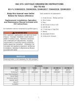
13 - LIGHTING INSTRUCTIONS
1. STOP! Read the safety information above.
2. Set the thermostat to lowest setting.
3. Turn off all electric power to the appliance.
4. This appliance is equipped with an ignition device
which automatically lights the pilot. Do not try to
light the pilot by hand.
OFF
ON
INLET
GAS CONTROL
KNOB
PILOT ADJUSTMENT
(UNDER CAP SCREW)
PILOT
OUTLET
OUTLET
WIRING
TERMINALS (2)
INLET
PRESSURE
TAP
TERMINALS
(2)
GROUND
PRESSURE
TAP
PRESSURE REGULATOR
ADJUSTMENT
(UNDER CAP SCREW)
OUTLET
5. Remove lower front panel.
6. Rotate the gas control knob clockwise to
“OFF”.
7. Wait ve (5) minutes to clear out any gas. Then
smell for gas, including near the oor. If you smell
gas, STOP! Immediately call your gas supplier
from a neighbor’s phone. Follow the gas
supplier’s instructions. If you don’t smell gas,
go to next step.
8. Rotate gas control knob counterclockwise to
“ON”.
9. Replace lower front panel.
10. Turn on all electric power to the appliance.
11. Set thermostat to desired setting.
12. If the appliance will not operate, follow the
instructions “To Turn Off Gas To Appliance” and call
your service technician or gas supplier.
TO TURN OFF GAS TO APPLIANCE
1. Set the thermostat to lowest setting.
2. Turn off all electric power to the appliance if
service is to be performed.
3. Push in gas control knob slightly and turn
clockwise to “OFF” Do not force.
WARNING
If you do not follow these
instructions exactly, a re or
explosion may result causing property
damage, personal injury or loss of life.
• This appliance is equipped with an ignition
device which automatically lights burner. Do
NOT try to light this burner by hand.
• Before operating smell all around appliance
area for gas. Be sure to smell next to oor
because some gas is heavier than air and
will settle to the oor.
• Use only your hand to turn the gas
shutoff valve. Never use tools. If valve
will not turn by hand, do not try to repair
it, call a qualied service technician. Force
or attempted repair may result in re or
explosion.
• Do not use this appliance if any part
has been under water. Immediately call
a qualied service technician to inspect
appliance and to replace any part of control
system and any gas control which has been
under water.
!
LIGHTING PROCEDURE FOR BOILER WITH
INTERMITTENT PILOT SYSTEM
For Your Safety, Read Before Operating!!
A. This appliance is equipped with an ignition device
which automatically lights the pilot. Do not try to
light appliance by hand.
CAUTION
WHAT TO DO IF YOU SMELL GAS
• Do not try to light any appliance.
• Do not touch any electrical switches; do not
use any phone in your building.
• Immediately call your gas supplier from a
neighbor’s phone. Follow the gas supplier’s
instructions.
• If you cannot reach your gas supplier, call
the re department.
!
Figure 15 - Automatic Gas Valve
/