The KitchenAid KMBS104EBL Microwave with Sensor Cooking offers a range of features to simplify your cooking tasks. With its 1.0 cu. ft. capacity, it can accommodate various dishes. Choose from 10 power levels to adjust the cooking intensity based on your needs. Utilize the Sensor Cooking feature for automatic adjustment of power and cooking time, ensuring perfectly cooked dishes. Conveniently defrost frozen foods using the Time Defrost function. Keep your food warm until ready to serve with the Keep Warm option.
The KitchenAid KMBS104EBL Microwave with Sensor Cooking offers a range of features to simplify your cooking tasks. With its 1.0 cu. ft. capacity, it can accommodate various dishes. Choose from 10 power levels to adjust the cooking intensity based on your needs. Utilize the Sensor Cooking feature for automatic adjustment of power and cooking time, ensuring perfectly cooked dishes. Conveniently defrost frozen foods using the Time Defrost function. Keep your food warm until ready to serve with the Keep Warm option.


-
 1
1
-
 2
2
-
 3
3
-
 4
4
-
 5
5
-
 6
6
-
 7
7
-
 8
8


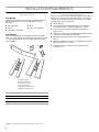
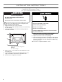
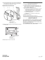
KitchenAid KMBS104EBL Installation guide
- Type
- Installation guide
- This manual is also suitable for
The KitchenAid KMBS104EBL Microwave with Sensor Cooking offers a range of features to simplify your cooking tasks. With its 1.0 cu. ft. capacity, it can accommodate various dishes. Choose from 10 power levels to adjust the cooking intensity based on your needs. Utilize the Sensor Cooking feature for automatic adjustment of power and cooking time, ensuring perfectly cooked dishes. Conveniently defrost frozen foods using the Time Defrost function. Keep your food warm until ready to serve with the Keep Warm option.
Ask a question and I''ll find the answer in the document
Finding information in a document is now easier with AI
Related papers
-
KitchenAid KBMS1454BWH Installation guide
-
-
-
KitchenAid KMBS104ESS Dimensions Guide
-
KitchenAid KMBS104EBL Dimensions Guide
-
KitchenAid KBMS1454RSS0 Installation guide
-
-
Whirlpool MKC2157AV Installation guide
-
KitchenAid KHHC2090SWH0 Installation guide
-
Other documents
-
Jenn-Air JJW8630DDB User manual
-
IKEA IBMS1455WS0 Installation guide
-
-
-
Amana JJW9130DD Installation guide
-
-
-
-
GE JXS81WW Installation guide
-
JennAir JMC3415ES Installation guide