Page is loading ...

Operating Instructions - Electric Pow'r-Riser Models
ADivisionOfTempleton, K enly & Co., Inc .
2525 Gardner Road . Broadview, Il. 60155 . (800)323-9114
Reference # 54119
Revison C
05/2007
Table of Contents
1.0 Recieving Instructions
2.0 Safety
3.0 Specifications
4.0 Initial Installation Before Operating Pump
5.0 Operation
6.0 Maintenance
7.0 Troubleshooting
Retrieve Technical Part Sheet Documentation, goto www.tksimplex.com

OPERATING INSTRUCTIONS AT A GLANCE
1.0 RECEIVING INSTRUCTIONS
Important! Make sure to inspect all of the components for shipping damage. If damage is found, notify carrier at once.
Shipping damage will not be covered by warranty. The carrier is responsible for all loss associated to shipping damage.
2.0 SAFETY
Make sure to read the instructions, warnings and precautions carefully. Follow
any recommended safety precautions to avoid personal injury or damage to the
unit. Simplex cannot be responsible for any damage or injury from unsafe use,
lack of maintenance or incorrect operation. In the event any questions or
concerns arise, contact SIMPLEX or a local Distributor for clarification.
The hydraulic system’s maximum working pressure is 10,000 PSI (700kg/cm
2
).
If you have never been trained on high-pressure hydraulic safety, consult your distributor or service center for a free
Simplex Hydraulic Safety Course.
Failure to comply with the following cautions and warnings could cause equipment damage, property damage or
personal injury.
CAUTION
is used to indicate correct operating or maintenance procedures and practices to prevent damage to,
or destruction of equipment or other property.
WARNING
indicates a potential danger that requires correct procedures or practices to avoid personal injury.
DANGER
is only used when your action or lack of action may cause serious injury or even death.
WARNING: Wear proper personal protective gear when
operating hydraulic equipment.
DANGER: To avoid personal injury, keep hands and
feet away from hydraulic unit and work-piece during
operation. Do not handle pressurized hoses. Escaping
oil under pressure can penetrate the skin, causing
serious injury. If oil is injected under the skin, see a
doctor immediately.
WARNING: This jack is for lifting only!! Support the
load after completing the lift by other appropriate
means. Never get under a load supported by the jack.
Never exceed the rated capacity of the jack. Allow at
least ten percent margin of safety.
WARNING: use jack only on solid surface compatible
of supporting the load and base of the jack. Always
center the load on the lifting saddle of the jack. If the
jack is not perpendicular to the load slipping or loss of
load is possible.
WARNING: Distribute the load evenly when performing
multiple lifts. Use only SIMPLEX hydraulic oil, or
approved equivalent. Failure to heed thee warning may
cause loss of load or failure of the jack resulting in
property damage or personal injury.
WARNING: Never use electrical motors in an explosive
atmosphere. Make sure the electrical connections are
grounded. Check that your power supply agrees with
the nameplate. The internal relief valve must not be
repaired adjusted except by an authorized service
center.
WARNING: Never set the relief valve to a higher
pressure than the maximum rated pressure. Higher
settings may result in equipment damage and/or
personal injury.
CAUTION: SIMPLEX CAN NOT BE RESPONSIBLE for
damage or injury from unsafe use application, or
maintenance of this product. READ and follow all
warnings, cautions, and instructions associated with
this product. Do not remove warning labels, tags, or
decals.
CAUTION: Fully retract the cylinder and protect the
entire unit from external damage. Keep Pow’r-Risers
clean, avoid weld splatter, and store in a clean dry area.
INSPECT ALL SYSTEM COMPONENTS BEFORE
USE.
CAUTION: Keep hydraulic equipment away from
flames and heat. Excessive heat will soften packing and
seals, resulting in fluid leaks. Heat also weakens hose
materials and packing. For optimum performance do
not expose equipment to temperatures of 65
0
C (170
0
F)
or higher.

2
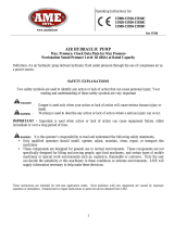
1
OIL FILLER CAP
3.0 SPECIFICATIONS
Component 115 Volt 230 Volt
Electrical Power Source 15 Amps 115 Volt Grounded 50/60HZ. 10 Amps 220 Volt Grounded 50/60 HZ.
Motor Rating 1 ½ HP Permanent Magnet 1 ½ HP Permanent Magnet
10 AMPS @ 10,000 PSI (700kg/cm²) 6 AMPS @ 10,000 PSI (700kg/cm²)
HP Reading (PSI) 60 ton = 6,000. 100 ton = 9,700. 150 ton = 10,200. 200 ton = 10,200.
Maximum Operating
Temperature
170 º F
Oil Capacity 5 Gallons.
4.0 INITIAL INSTALLATION BEFORE OPERATING SYSTEM
4.1 Working Pressure
The factory preset system pressure for 60 ton is 6,000psi, 100 ton is 9,700psi, 150 ton
is 10,200psi, and 200 ton is 10,200psi.
4.2 Adding Oil
Remove OIL FILLER CAP and add SIMPLEX Hydraulic Oil into
reservoir. Oil level should not exceed 1” from the reservoir cover.
WARNING: Loose or improperly threaded fittings can be potentially dangerous if pressurized, however, severe over
tightening can cause premature thread failure. Fittings need to be tightened secure & leak free. Never hold or stand
directly in line with any hydraulic connections while pressurizing. Never grab, touch or in any way come in contact with a
hydraulic pressure leak. Escaping oil can penetrate the skin and a serious injury can result.
4.3 Electrical
Check for proper electrical supply before connecting. Be sure the electrical connection is grounded. Check that your
power supply agrees with the motor nameplate and/or Simplex model decal.
NOTE: THIS MOTOR MAY SPARK. DO NOT OPERATE IN AN EXPLOSIVE ATMOSPHERE OR IN THE PRESENCE
OF CONDUCTIVE LIQUIDS.
a. Do not use a power or extension cord that is damaged or has exposed wiring.
b. All single phase motors come equipped with a three prong grounding type plug to fit the proper grounded
type electrical outlet. Do not use a two prong ungrounded extension cord as the pump’s motor must be
grounded.
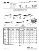
4.4 How to use the Handle Assembly
1. Push lever (callout #1) to release locking pin.
2. Raise handle assembly (callout #2) upward and pull handle assembly (#1) to
engage lock pin into desire hole setting.
3. Pow’r-Riser can now be pushed or pulled (be mindful walking backwards) to
work area.
4. If necessary, the Pow’r-Riser should be picked up by the lifting bar, or by the
eyebolt for higher ton models (callout #3). Never attempt to pick jack up by
handle assembly.

To Retract
To Advance
3/4 Way Manual Valve;
handle position is in center.
ADV
RET
3/4Way Solenoid Valve; stays in center position until switch is depressed
Momentary pendant switch stays
in center position until depressed
to advance or retract valve
electrically.
Pendant Switch
4.5 Using the Jack for the First Time
1. Locate the valve control and make sure it’s in the
neutral or center position.
2. Locate the power switch on the pendant and select to
the “ON” position. Check for any leaks, repair as needed.
3. Shift the control valve to the advance and retract position
and look for movement in cylinder. Check for any leaks, repair
as needed.
5.0 OPERATION
5.1 Control Valves:
4-Way Manual Valve
x Pushing lever to right directs pump
output to “A” port.
x Pushing lever to left directs pump
output to “B” port.
x Center position is neutral/hold.
Pump output is directed back to
tank.
4-Way Solenoid Valve
To
Advance…depress switch to the ADV
position.
x For Neutral/Hold…release switch.
x To Retract…depress switch to the
RET position.
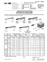
5.2 BASIC OPERATING INSTRUCTIONS
TO RAISE LOAD: (Refer to diagram on next page).
1. Push lever (callout #1) to release locking pin.
2. Raise handle assembly (callout #2) upward and pull handle assembly (callout #1) to engage lock pin into desire
hole setting.
3. Pow’r-Riser can now be pushed or pulled (be mindful walking backwards) to work area.
4. The Pow’r-Riser must be positioned on a solid foundation with wooden or hard rubber pads between the load
and the jack. IMPORTANT NOTE: The jack must be perpendicular to the load; jacking on an angle can result
in the jack slipping out and loss of load.
5. Once the Pow’r-Riser has been placed on a solid support surface, final positioning can be accomplished by
lowering the handle to its horizontal position to scoot the jack under the loads as required.
6. Be certain the electrical switch (callout #4) is in the “off” position. Check the control valve handle to be sure it is
in the “IDLE” (neutral or center) position.
7. Depress the electrical switch (callout #4) to start the motor, then move the control valve handle (callout #5) to
advance cylinder.
8. When load has reached the proper level, place the control valve handle (callout #5) back to center or neutral
position. No Ram movement for more than one minute, SIMPLEX recommend the motor be turn off to prevent
overheating.
PENDANT SWITCH

CAUTION: Special care must be taken to keep the load level. Leveling is best accomplished by jogging the
electrical switch on the pendant (callout #4).
9. Secure the load by using the proper Simplex auxiliary U-Rings and/or appropriate blocking or supports stands.
(Refer to the U-ring Stacking Instructions for details).
TO LOWER THE LOAD:
1. Shift the control valve handle (callout #5) to return valve back to center or neutral position
2. Depress the electrical switch on the pendant (callout #4) to start motor.
3. Shift the control valve handle (callout #5) to the advance position to clear auxiliary stands or U-rings, place the
directional control valve handle in idle (neutral or center) position.
4. When the auxiliary stands or u-rings are removed, shift the control valve handle (callout #5) to the retract
position to lower the cylinder. Be mindful while lowering to ensure that the load is lowered evenly to prevent
load shifting.
5. When piston has fully retracted, place directional control valve handle in idle (neutral or center) position and turn
off motor via pendant (callout #4).
2
5
6
3
1
4


5.3 Jacking Safely
You must know the weight of what you intend to lift and choose a jack with at least
10% more capacity.
Never
crawl or place any part of your body under any load at any time. Insert lock rings as you lift. Jacks are meant for
lifting only and should not be used to support the load for any period of time.
You should obtain and be familiar with the American National Standards Institute rules that apply to hydraulic rams and
jacks (ASME ANSI B30.1).
5.4 After Completing the Job
Fully retract the cylinder, then unplug the power cord and shift the hydraulic controls several times to release system
pressure. Store the unit in a clean, dry area.
6.0 MAINTENANCE
6.1 Periodic Maintenance
Change the hydraulic oil and clean the oil filter screen and magnet (located in the reservoir) twice a year. (Use Simplex oil
only, Model # AO5, 5 gallon). Change the oil more frequently when used in extremely dusty areas or when the oil has
been overheated. Using oil other than Simplex Brand may void the pumps warranty.
WARNING: THE ELECTRICAL POWER CORD MUST BE DISCONNECTED FROM ELECTRICAL OUTLETS BEFORE
PERFORMING MAINTENANCE OR REPAIR PROCEDURES.
6.2 Maintain Oil Level
Check hydraulic oil level every 30 hours of operation. Add Simplex oil (Model # AO1 – 1 gallon) when necessary. Oil level
should be no more than 1” from top of reservoir plate – with cylinders retracted and motor off.
Change oil at least twice a year. The following conditions require more frequent oil changes.
x Rigorous duty, where oil temperature may reach 150
0
F.
x High humidity environment and extreme changes in temperature that can result in condensation inside the
reservoir.
x Dirty or dusty environments that may contaminate the oil.
x Frequent connection and disconnection of hydraulic hoses and components.
6.3 Clean Oil Filter Screen Once a Year
Loosen and remove reservoir plate bolts. Lift pump unit off the reservoir, being careful not to damage the gasket. Unscrew
screen from bottom of pump unit and clean with nonflammable solvent. Blow dry and reassemble. Keep areas around
pump unobstructed to provide good air flow around the motor and pump. Keep the motor and pump as clean as possible.
6.4 Flush the Pump
If you suspect your pump has been contaminated or discover sludge or other deposits on internal components, you
should thoroughly flush the pump. Remove the old oil from the reservoir, then thoroughly clean the reservoir and refill with
a clean, nonflammable flushing oil. Reassemble the pump and motor to the reservoir.
Now run the pump in no load
condition for 1 or 2 minutes maximum. Unplug the pump and remove the motor and pump
assembly again. Now drain the flushing oil and re-clean the inside of the reservoir. (Make sure flushing fluid is also
drained from pump assembly). Refill the reservoir with Simplex hydraulic oil and reassemble the pump.

7.0 TROUBLESHOOTING
PROBLEM CAUSE-SOLUTION
Sporadic Cylinder Action
x Air in the hydraulic system. Cycle jack up / down several times
x Check reservoir oil level.
Motor Will Not Start
x Be sure power cord is not damaged.
x Check for tripped circuit breaker; be sure breaker is of adequate size.
x Have motor checked for proper operation.
x Have qualified electrician inspect for loose or faulty wiring or switch.
Noisy Operation
x Air in system.
x Be sure the oil reservoir is filled to normal level.
x Check all points where air might leak into system.
x Clogged or blocked intake screen.
Pump Oil is Over
Heating
x Oil viscosity too high. Replace with Simplex Oil.
x Check for high pressure leakage at the pump (leaking at plug or relief valve).
x Oil level is low. Fill reservoir to normal level, or retrofit the pump with larger
reservoir or heat exchanger.
Pump Runs But Will Not
Pump Oil or piston rod
moves but will not lift
load. x Pump is not primed. Run the motor a few minutes.
x Check to make sure that external adjustable relief valve set properly.
x Damaged O-Rings. Take to nearest Simplex authorized service center for
repair.
x Defective control valve.
x Incorrect motor rotation, take to nearest Simplex Authorized Service Center.
Piston Extends but will
not retract. x Pump not developing enough pressure (2,500 PSI required for retraction).
x Check for internal pressure leaks, or leaking retract hoses.
x Adjust internal Relief and retract side relief.
x Defective O.C. Valve. Defective secondary lock valve.
WARRANTY STATEMENT
SIMPLEX products are warranted to be free of defects in materials and workmanship under normal use for as long as the
original purchaser owns them, subject to the guidelines and limitations listed. This warranty does not cover: normal wear
& tear, cosmetic items, abuse, overloading, alterations, improper fluid, or use in a manner for which they are not intended.
If the customer believes a product is defective, the product must be delivered, or shipped freight prepaid, to the nearest
SIMPLEX Authorized Service Center for evaluation and repair.
/