Page is loading ...

G5 AIR TORQUE
POWER PUMPS
Reference # - TD061
Rev. - A
Date - 0810
- Note -
SIMPLEX has taken every care in preparing this Operational Manual that is intended as a technical guideline only.
SIMPLEX accepts no liability in relation to any use or reliance made of any information in this Operational Manual.
e based on the latest information
available at the time of publication. The right is reserved to make changes at any time without notice.
Equipment operators and installers shall be responsible for ensuring that a safe working environment and safe
systems of work are in place before operating the equipment.
©2010 SIMPLEX
CONTENTS
Receiving Instructions and Warranty Statement .........................................................................................................2
Safe and Correct Use ...................................................................................................................................................3
Technical Specifications ...............................................................................................................................................4
Working Pressure .........................................................................................................................................................4
Install Vent Plug ............................................................................................................................................................4
Adding Oil .....................................................................................................................................................................4
Connecting Hydraulic Tools...................................... ....................................................................................................4
Pump Mounting ............................................................................................................................................................4
Control Valves & Pendant .............................................................................................................................................5
Pressure Toque Settings ..............................................................................................................................................5
Air Motor and Filter Lubricator .....................................................................................................................................6
After Completing the Job .............................................................................................................................................6
Periodic Maintenance ...................................................................................................................................................6
Maintain Oil Level .........................................................................................................................................................6
Clean Oil Intake Screen ................................................................................................................................................7
Flushing the Pump .......................................................................................................................................................7
Troubleshooting ............................................................................................................................................................8
TO RETRIEVE TECHNICAL PART SHEET DOCUMENTATION, GO TO: WWW.TKSIMPLEX.COM
777 Oakmont Lane, Westmont, IL 60559
1.800.323.9114 • Outside U.S. 1-630-590-6990
www.tksimplex.com

••• 2 •••
IMPORTANT - READ CAREFULLY
This manual contains important information for the correct installation, operation and maintenance of this
equipment. All persons involved in the installation, operation and maintenance of this equipment must be
thoroughly familiar with the contents of this manual. To safeguard against the possibility of personal injury or
property damage, follow the recommendations and instructions of this manual. Keep this manual for reference.
WARRANTY STATEMENT
SIMPLEX products are warranted to be free of defects in materials and workmanship under normal use for
as long as the original purchaser owns them, subject to the guidelines and limitations listed. This warranty does
not cover: normal wear & tear, cosmetic items, abuse, overloading, alterations, improper fluid, or use in a
manner for which they are not intended. If the customer believes a product is defective, the product must be
delivered, or shipped freight prepaid, to the nearest SIMPLEX Authorized Service Center for evaluation and
repair.
1.0 RECEIVING INSTRUCTIONS
Important! Make sure to inspect all of the components for shipping damage. If damage is found, notify carrier at
once. Shipping damage will not be covered by warranty. The carrier is responsible for all loss associated with
shipping damage.
G Series Air Power Pumps

www.tksimplex.com
••• 3 •••
2.0 SAFETY
Make sure to read the instructions, warnings and precautions carefully. Follow any recommended safety precautions
to avoid personal injury or damage to the unit. Simplex cannot be responsible for any damage or injury from unsafe
use, lack of maintenance or incorrect operation. In the event any questions or concerns arise, contact SIMPLEX or a
local Distributor for clarication.
The pump’s maximum working pressure is 10,000 PSI (700kg/cm
2
). Make
sure that all tools used with this pump are rated at 10,000 PSI (700kg/cm
2
)
operating pressure.
If you have never been trained on high-pressure hydraulic safety, consult
your distributor or service center for a free Simplex Hydraulic Safety Course.
Failure to comply with the following cautions and warnings could cause equipment damage, property damage or
personal injury.
DANGER is only used when your action or lack of action may cause serious injury or even death.
WARNING indicates a potential danger that requires correct procedures or practices to avoid personal injury.
CAUTION is used to indicate correct operating or maintenance procedures and practices to prevent damage
to, or destruction of equipment, or other property.
WARNING: Wear proper personal protective gear when operating hydraulic equipment.
DANGER: To avoid personal injury, keep hands and feet away from tool and work-piece during operation.
WARNING: Do not exceed equipment ratings. Overloading causes equipment failure and possible personal injury.
The tools are designed for a maximum pressure of 10,000 PSI (700kg/cm
2
). Do not connect a tool to a pump with a
higher pressure rating. Never set the relief valve to a higher pressure than the maximum rated pressure of the pump.
Higher settings may result in equipment damage and/or personal injury.
WARNING: The system operating pressure must not exceed the pressure rating of the lowest rated component in
the system. Install pressure gauges in the system to monitor operating pressure. It is your window to what is
happening in the system.
CAUTION: Avoid damaging hydraulic hose. Avoid sharp bends and kinks when routing hydraulic hoses. Using a
bent or kinked hose will cause severe back-pressure. Sharp bends and kinks will internally damage the hose, leading
to premature hose failure.
Do not drop heavy objects on hose. A sharp impact may cause internal damage to hose wire strands. Applying
pressure to a damaged hose may cause it to rupture.
IMPORTANT: Do not lift hydraulic equipment by the hose or swivel couplers. Use the carrying handle or other means
of safe transport.
CAUTION: Keep hydraulic equipment away from ames and heat. Excessive heat will soften seals, resulting in uid
leaks. Heat also weakens hose materials. For optimum performance do not expose equipment to temperatures of
65° C (170° F) or higher. Protect hoses and cylinders from weld spatter.
DANGER: Do not handle pressurized hoses. Escaping oil under pressure can penetrate the skin, causing serious
injury. If oil is injected under the skin, see a doctor immediately.
DANGER: Only use hydraulic tools in a coupled system. Never use a tool with unconnected couplers. If the cylinder
becomes severely overloaded, components can fail catastrophically causing severe personal injury or death.

••• 4 •••
A
C
B
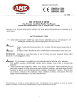
VENT PLUG OIL FILL LOCATION IS APPLICABLE
TO THE 1.5, 2.5, GALLON RESERVOIRS
3.0 TECHNICAL SPECIFICATIONS
G5 Air Torque Series
Operating Pressure 10,000 PSI (700kg/cm
2
)
Motor Rating Rotary Air Valve, 3 hp Motor (3,000 rpm)
90 psi / 50 cfm
Flow Rate 700 cu. in./ min. @ 1,100 psi, 55 cu. in / min. @ 10,000 psi
Maximum Operating Temperature 170̊F - (65̊C)
4.0 WORKING PRESSURE
The pump’s maximum working pressure is 10,000 PSI (700kg/cm
2
). Make sure that all hydraulic equipment such as
rams, hoses, etc. used with this pump are rated at 10,000 PSI (700kg/cm
2
) operating pressure.
4.1 INSTALL VENT PLUG
Remove SHIPPING PLUG (A) and install VENT PLUG (B) into cover
plate.
4.2 ADDING OIL
Remove OIL FILLER CAP (C) and add SIMPLEX Hydraulic Oil into
reservoir. Oil level should not exceed 1” from the reservoir cover.
As a “rule of thumb” oil should be visual in site window when the
unit is powered down and all connected tools or cylinders are
retracted.
4.3 CONNECTING HYDRAULIC TOOLS
Use only tools, hoses and accessories rated at 10,000 PSI (700kg/cm
2
). When making connections with quick dis-
connect couplings, make sure the couplings are fully engaged. Threaded connections such as ttings, gauges, etc.
must be securely tightened and leak free. Use 1.5 wraps of Teon tape (or suitable thread sealant) on all threads,
leaving the rst complete thread free of tape to ensure no foreign matter enters the hydraulic circuit.
WARNING: Loose or improperly threaded ttings can be potentially
dangerous if pressurized; however, severe over tightening can cause premature thread failure. Fittings need to be
tightened secure & leak free. Never hold or stand directly in line with any hydraulic connections while pressurizing.
Never grab, touch or in any way come in contact with a hydraulic pressure leak.
Escaping oil can penetrate the skin and a serious injury can result.
CAUTION: Do not subject the hose to potential hazards such as sharp surfaces, extreme heat or heavy impact.
Do not allow the hose to kink or twist. Inspect each hose for wear before it is used.
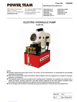
4.4 PUMP MOUNTING Refer to the chart for mounting dimensions to secure the pump to a xed surface.
1.5 gal.(6L) 2.5 gal.(10L)
A
15.13 17
B
3.68 4.75
C
1.57 2.37
D
1.43 1.93
E
8.75 9.75
F
1/4-20unc
(4 places)
1/4-20unc
(4 places)
A
B
C
D
E
F

www.tksimplex.com
••• 5 •••
5.0 CONTROL VALVES & PENDANT
2-Postion – 4 Way Solenoid Valve for Hydraulic Torque Wrenches.
• To Advance......depress the Advance Switch
• To Retract.........release advance switch to Retract Tool.
Remote pendant switch control as follows:
Congured with motor/valve control pendant:
ADVANCE = Press and hold switch to activate advance
coil and turn motor on.
RETRACT = Release “run” button, press “stop” button to
turn off motor.
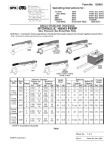
5.1 PRESSURE TORQUE SETTING
WARNING: Make these adjustments BEFORE putting torque wrench on
nut or bolt head. The pump pressure setting may be above the
pressure needed to provide the required torque for your application.
Exceeding required torque will cause equipment damage and may lead to
serious personal injury.
1. See torque wrench instructions for amount of pressure required
to produce desired torque.
2. Loosen lock nut and back out relief valve to prevent unintended
pressure build up.
3. Turn pump on. Press and the “ADVANCE” switch, and read
pressure gauge.
4. While holding the switch, turn relief valve in (clockwise).
to increase pressure or out (counter-clockwise)
to decrease maximum pressure. Repeat until
correct pressure is obtained.
5. Tighten lock nut on the relief valve to maintain setting.
6. Run pump several times to test this setting before
setting tool on the nut.
2 Position - 4 Way Solenoid
STOP RUN
Retract Advance
Valve Assembly
Adjusting Knob
Lock Nut

••• 6 •••
5.2 AIR MOTOR AND FILTER LUBRICATOR
The air motor is a precision built rotary motor. The top clearance (between rotor and bore) is .0015”. The total end
clearance (between the sides of the rotor and the end plates is .002”. The vanes take up their own wear and will last
5,000-12,000 hours, depending upon speed, method of oiling, operating pressure, and lend itself to operating pres-
sure above 100PSI (6.89 Bar-Metric). Allowing excess moisture or foreign particles from the air line to enter the motor
will nullify the guarantee.
A moisture trap and lter has been installed in the air line ahead of motor. For efciency of output and control of
speed, use air line of not less then 1/2” pipe size. When coupling or connecting the motor to a drive member, avoid
any end or side thrust on the output shaft and especially DO NOT HAMMER ON SHAFT.
The starting torque is more than the running torque and could vary depending on the position at which the vanes
stop in relation to the air intake port. The speed and torque can be regulated by using a pressure regulator or a sim-
ple shut-off valve. Lubrication is necessary for the shaft seal, and rust prevention. Each air powered jack is equipped
with an automatic air line oiler set to feed 1-3 drops per minute. Use simplex #18243 antifreeze oil. Excessive mois-
ture in the line can cause rust formation in the motor and might also cause ice to form in mufer due to expansion of
air through the motor.
NOTE: To adjust oiler drops, turn dial counter clockwise to “raise”, and clockwise to “lower”.
If the motor is sluggish or inefcient, try ushing with solvent in well ventilated area. Disconnect the air line and
mufer and add several teaspoons of solvent. Rotate the shaft by hand in both directions for a few minutes, again
connect the air line and apply pressure slowly until there is no trace of solvent in exhaust air. (Keep face away from
exhaust air). Check the mufer felts for grease, dirt, etc. If dirty, wash them in solvent. Replace the felts and connect
the mufer. Relubricate the motor with a squirt of oil in the chamber. If the vanes need replacing, or foreign particles
are present in motor chamber, an experienced mechanic may remove the end plate apposite the drive shaft end.
DANGER: To prevent explosive hazard, do not pump combustible liquids or vapors through these units.
5.3 AFTER COMPLETING THE JOB
Before disconnecting hoses, ttings, etc., rst be sure the tool is unloaded and retracted, then unplug the power
cord and shift the hydraulic controls several times to release system pressure. Store the pump in a clean, dry area.
6.0 PERIODIC MAINTENANCE
Completely change the hydraulic oil and clean the intake screen and magnet (located in the reservoir) twice a year. If
equipped, change the external oil lter twice a year (Use Simplex oil only, Model # AO1, 1 gallon). Change the oil
more frequently when used in extremely dusty areas or when the oil has been overheated. Using oil other than
Simplex Brand may void the pump’s warranty.
The following conditions require more frequent oil changes.
• Rigorous duty, where oil temperature may reach 150°F.
• High humidity environment and extreme changes in temperature that can result in condensation inside the
reservoir.
• Dirty or dusty environments that may contaminate the oil.
• Frequent connection and disconnection of hydraulic hoses and components.
6.1 MAINTAIN OIL LEVEL
Check hydraulic oil level every 30 hours of operation (sight gauge should be completely covered in oil when all tools
are retracted. Add Simplex oil (Model # AO1 – 1 gallon) when necessary. Oil level should be no more than 1” from
top of reservoir plate – with cylinders retracted and motor off.

www.tksimplex.com
••• 7 •••
6.2 CLEAN OIL INTAKE SCREEN ONCE A YEAR
Loosen and remove reservoir plate bolts. Lift pump unit off the reservoir, being careful not to damage the gasket.
Applies to 1.5, 2.5 gallon reservoirs:
Remove the 5 Allen socket head cap screws securing the screen to the 1st stage gear pump. Care should be taken
not to remove the center plate and gears. Remove and clean with nonammable solvent, blow dry clean. Reinstall in
reverse order and torque bolts to 75 inch pounds. Keep the motor and pump as clean as possible.
Applies to the 5 and 10 gallon reservoirs:
Unscrew screen from bottom of pump unit and clean with nonammable solvent. Blow dry and reassemble. Keep
areas around pump unobstructed to provide good air ow around the motor and pump. Keep the motor and pump
as clean as possible.
6.3 FLUSH THE PUMP
If you suspect your pump has been contaminated or discover sludge or other
deposits on internal components, you should thoroughly ush the pump. Re-
move the old oil from the reservoir, then thoroughly clean the reservoir and rell
with a clean, nonammable ushing oil. Reassemble the pump and motor to the
reservoir. Now run the pump in no load condition for 1 or 2 minutes maximum.
Unplug the pump and remove the motor and pump assembly again. Now drain
the ushing oil and re-clean the inside of the reservoir. (Make sure ushing uid
is also drained from pump assembly). Rell the reservoir with Simplex hydraulic
oil and reassemble the pump.
Oil Fill (1.5 - 10 Gal. Models)
Sight Gauge
Drain Plug (1.5 - 10 Gal.)

••• 8 •••
7.0 TROUBLESHOOTING
PROBLEM CAUSE - SOLUTION
Sporadic Cylinder Action: • Air in the hydraulic system. Bleed the hydraulic circuit.
• Check reservoir oil level.
Motor Will Not Start: • Have motor checked for proper operation.
• Have qualied electrician inspect for loose or faulty switch.
Noisy Operation: • Air in system.
• Be sure the oil reservoir is lled to normal level.
• Check all points where air might leak into system.
• Clogged or blocked intake screen.
Pump Oil is Over Heating: • Inspect for high pressure leakage at the pump (leaking at plug or
relief valve).
• Oil level is low. Fill reservoir to normal level, or retrot the pump with
larger reservoir or heat exchanger.
Pump Runs But Will Not Pump Oil: • Pump is not primed. Run pump a few minutes tipping from side to
side.
• Inspect to make sure that external adjustable relief valve is set
properly.
• Defective control valve, take to nearest Simplex Authorized Service
Center for repair.
• Incorrect motor rotation, take to nearest Simplex Authorized Service
Center for repair.
• Check to make sure the intake screen is not clogged. Clean if
needed.
• Check oil reservoir is low. Fill as needed.
• Oil viscosity is too high. Replace with SIMPLEX oil.

www.tksimplex.com
••• 9 •••
notes:

••• 10 •••
notes:

www.tksimplex.com
••• 11 •••
notes:

Printed in the U.S.A.
UNITED STATES HOME OFFICE
777 OAKMONT LANE, STE. 800 - WESTMONT, IL 60559
PHONE: 1-630-590-6990 • FAX 1-630-590-6955 • TOLL FREE:1-800-323-9114
EMAIL: [email protected] • www.tksimplex.com
/