Page is loading ...

MAC
3
Wind Speed Alarm & Controller
Installation Instructions

2
Table of Contents
Overview .......................................................................................................... 3
Installation ....................................................................................................... 3
Optional Equipment ...................................................................................... 9
Relay Cable ................................................................................................ 9
Dual Sensor Operation ............................................................................ 10
Other Optional Equipment ...................................................................... 10
Operation Manual ........................................................................................ 10
MAC3 Data Display .................................................................................... 15
Additional Features ................................................................................. 16
Display Adjustments ................................................................................ 18
Wind Settings ........................................................................................... 18
Alarm & Control Settings ......................................................................... 22
Tests ......................................................................................................... 29
Troubleshooting ........................................................................................... 32
Specifications ................................................................................................ 33
Components .................................................................................................. 34

3
Overview
Thank you for purchasing the MAC
3
wind speed alarm and controller. This
manual is designed to lead you through a step-by-step process to install and
operate the MAC
3
properly. Please read thoroughly prior to installation.
Note: If this unit is being used as an ALARM, it is to be used as an aide to
your current safety program, and it is not to be used exclusively in
operations that may affect personal and/or property safety. Please do not
use the time delay feature when using the instrument as a wind speed
alarm.
It is advisable to bench test your MAC
3
prior to final installation.
Installation
PROPER INSTALLATION IS
IMPORTANT. IF YOU NEED
ASSISTANCE, CONSULT A
CONTRACTOR, ELECTRICIAN,
TELEVISION ANTENNA INSTALLER, OR
HOME ELECTRONICS SPECIALIST. CHECK
LOCAL BUILDING CODES PRIOR TO
INSTALLATION.
1. Determine where the MAC
3
read out and wind
speed sensor(s) will be located.
A. Feed the terminal lug end of the shielded wind
speed cable through the bottom of the enclosed
rubber boot and connect the lugs to the
terminals on the bottom of the wind speed sensor
(no polarity) using the supplied 4-40 nuts in the
hardware bag. Do not adjust the nuts that
are already on the sensor.

4
B. Slide the stub mast through the rubber boot and insert
the stub mast into the bottom of the wind speed sensor.
Secure the sensor to the mast using the cotter pin supplied in the
hardware bag. Coat all wire connections with a rubber silicone
sealant and slip the boot over the sensor.

5
C. Secure the sensor and the stub mast to your antenna mast (not
supplied, but available) with the two hose clamps supplied in the
hardware bag. Choose a mount that best suits your location and
provides at least eight feet of vertical clearance.
D. Follow the instructions suplied with the antenna mount (not
included, but available). Secure the wire to the building or structure
using proper cable clips (not included).

6
E. Wire the included MAC
3
power/sensor shielded cable to the
terminal strip supplied in the hardware bag. Terminal strip is
marked 1-6, where:
1 = Red = +12VDC/24VDC
2 = Black = Common from Power Supply
3 = White = Sensor 1 (no polarity)
4 = Green = Sensor 1 (no polarity)
5 = Orange = Sensor 2 (optional, no polarity)
6 = Blue = Sensor 2 (optional no polarity)

7
F. Attach the MAC
3
power/sensor shielded cable to the left socket and
twist the cap to lock it in place.
G. Apply proper voltage (12VDC to
24VDC) to terminals 1 and 2
of the terminal strip.
Follow screen prompts on
the MAC
3
(see operating
instructions).

8
H. Secure MAC
3
indicator in a proper mounting location using the
screws supplied in the hardware bag. Secure the terminal strip with
the screws supplied in the hardware bag to ensure the wire
connections are stable. The MAC
3
indicator and anemometer are
weather-tight to the IP65 standard and are rated for use from -40°F
to 158°F (-40°C to 70°C).

9
Optional Equipment
Relay Cable
With the optional relay cable (EA077) you have access to the output of two
(2) 5A SPDT relays that can control external devices. To install:
1. Remove the waterproof cap on the right connector on the MAC
3
indicator.
2. Plug the relay cable (EA077) into the connector.

10
Dual Sensor Operation
The MAC
3
can be configured for simultaneous use with dual sensors to
monitor wind speed in two separate locations. An optional second sensor
(Kit-#400) can be installed to the orange and blue wires from the
power/sensor cable. Follow the set up instructions to select 2 sensor
operation.
Other Optional Equipment
Part #: EA065 12VDC Power Supply
Part #: WM033 100’ 2-Conductor Shielded Cable
Part #: WM030 2-Conductor Shielded Cable sold
by the foot, 1000’ maximum length
Part #: EH110 External Siren
Operation Manual
1. Connect the MAC
3
to a 12 or 24VDC power source per the installation
instructions.
a. MAC
3
will conduct a self-test at initial power-up. Once complete,
you will see the welcome screen (only for initial set up).

11
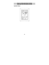
2. Keypad
a. The MAC
3
keypad
allows the user to
navigate through the
screens and options
of the wind speed
alarm & controller.
Up/Down Arrow Keys
: Allows user to
navigate through
the options to
select proper
setting.
BACK
: Brings the user to
the previous screen.
CANCEL
: Will cancel the selection and bring the
user back to the Data display screen.
DISPLAY
: Enable the main Menu while in the
Data display screen.
LEDs
: The left LED will turn on YELLOW when set-point
1 is reached as a visual aide.
The right LED will turn on RED when set-point 2
is reached as a visual aide.
3. Guided Set-Up
a. Follow the screen prompts through the set-up procedure. To cancel
set-up mode, press the CANCEL button on the keypad at any time.
Press the BACK button at any time to return to the previous step.
Setting any feature to 0000 disables that function.

12
4. Select Units of Measure
a. Using the up/down arrow keys scroll to select the desired UNITS (of
measurement), press OK.
5. Select Sensors
a. Using the up/down arrow keys, select the NUMBER OF SENSORS
installed, press OK.

13
6. Set Points
a. Using the up/down arrow keys, select the hundred’s value for Set
Point 1, press OK.
b. Using the up/down arrow keys, select the ten’s value for Set Point 1,
press OK.
c. Using the up/down arrow keys, select the one’s value for Set Point 1,
press OK.
d. Using the up/down arrow keys, select the hundred’s value for Set
Point 2, press OK.
e. Using the up/down arrow keys, select the ten’s value for Set Point 2,
press OK.
f. Using the up/down arrow keys, select the one’s value for Set Point 2,
press OK.
g. Follow Steps 1-6 if you selected the optional two sensor installation
to set values for sensor 2.
7. Controller Lock
The CONTROLLER LOCK feature allows the user to lock out unauthorized
personnel from changing the controller settings. If the Lock Code is set and
is then lost, the unit will need to be returned to the factory to reset the code.
By pressing the CANCEL button, no Lock Code will be retained and the

14
MAC
3
will display current conditions and settings. If the code is set to 0000,
the lock feature will be disabled.
a. Using the up/down arrow keys select the first number, press OK.
b. Using the up/down arrow keys select the second number; press OK.
c. Using the arrow keys select the third number, press OK.
d. Using the arrow keys select the fourth number, press OK. Once the
fourth number is set, the lock feature will be enabled.
e. Enter an Employee number as a record of who entered the Lock
Code. Using the up/down arrow keys select the first number, press
OK.
f. Using the up/down arrow keys select the second number; press OK.
g. Using the up/down arrow keys select the third number, press OK.
h. Using the up/down arrow keys select the fourth number, press OK.
The MAC
3
is now fully operational. Set-Point 1 controls relay #1, Set-Point 2
controls relay #2. Relays will activate when the wind speed reaches the
selected SETPOINTS. When the wind speed reaches a single Set-Point, the
buzzer will sound every second. When both Set-Points have been met, the
buzzer will sound continuously.

15
MAC3 Data Display
1. With one (1) installed sensor
a. When 1 installed sensor is selected, the display will show the current
wind speed in the units of measurement previously selected; a
running 1-minute average wind speed (unless the average was
changed to 2, 5, or 10 minutes); the MAX wind gust since last reset,
and the Set-Point values currently selected.
b. When Set-Point 1 is reached, the buzzer will sound an alternating
beep, the word TRIP will be highlighted on the display above the
word LOW, and the yellow LED on the keypad will light. When Set-
Point 2 is reached, the beep will become steady and the word TRIP
will be highlighted on the display above the words LOW and HIGH,
and the red LED on the keypad will light.
c. Gust Reading: The MAX wind gust reading may be reset by pressing
the OK and BACK buttons simultaneously.
2. With two (2) installed sensors

16
a. When an optional 2 sensor set up is used, the screen will split and
display the current wind speed in the units of measurement
selected for both sensors; a running 1-minute average (unless the
average was changed to 2, 5, or 10 minutes); the MAX wind gust
since last reset, and the Set-Point values selected for the individual
Set-Points as SP1 and SP2.
b. When Set-Point 1 is reached, the buzzer will sound an alternating
beep and the word SP1 will change to TRIP, which will be
highlighted, and the yellow LED on the keypad will light. When Set-
Point 2 is reached, the beep will become steady and the word SP2
will change to TRIP, which will be highlighted, and the red LED on
the keypad will light. This will be the same for sensors 1 and 2.
c. Gust Reading: The MAX wind gust reading may be reset by pressing
the OK and BACK buttons simultaneously.
Additional Features
The MAC
3
Wind Speed Alarm & Controller has many features that can be
customized for your particular installation. If the indicator’s lock out feature
has been enabled, you will need the unlock code prior to proceeding with
changes. If the indicator’s features have not been locked you will be able to
access the MAIN MENU by pressing the DISPLAY button on the indicator.
Please note that the screen will revert to the data display if it detects no
keypad activity for 1 minute.
1. Changing the Unlock Code

17
a. Select CHANGE UNLOCK CODE using the up/down arrow keys, then
press OK. A code of 0000 will disable the lock feature. If the MAC
3
has been locked and the unlock code is not known, you can return
the unit to Maximum to have the code reset.
b. Using the up/down arrow keys, set the first number of the CURRENT
CODE, press OK.
c. Using the up/down arrow keys, set the second number of the
CURRENT CODE, press OK.
d. Using the up/down arrow keys, set the third number of the
CURRENT CODE, press OK.
e. Using the up/down arrow keys, set the fourth number of the
CURRENT CODE, press OK.
f. Using the up/down arrow keys, set the first number of the NEW
CODE, press OK.
g. Using the up/down arrow keys, set the second number of the NEW
CODE, press OK.
h. Using the up/down arrow keys, set the third number of the NEW
CODE, press OK.
i. Using the up/down arrow keys, set the fourth number of the NEW
CODE, press OK.

18
j. Using the up/down arrow keys, set the first number of the
EMPLOYEE CODE, press OK.
k. Using the up/down arrow keys, set the second number of the
EMPLOYEE CODE, press OK.
l. Using the up/down arrow keys, set the third number of the
EMPLOYEE CODE, press OK.
m. Using the up/down arrow keys, set the fourth number of the
EMPLOYEE CODE, press OK.
MAC
3
will return to the data display screen when the final number is
entered.
Display Adjustments
1. Brightness/Contrast: Adjust the brightness and contrast of the display
using the buttons on the indicator. This feature will only work on the
data display, not when inside one of the menus.
a. To adjust Brightness, press and hold the BACK button on the
indicator. Use the up/down arrow keys to adjust the display to the
desired brightness level.
b. To adjust Contrast, press and hold the CANCEL button on the
indicator. Use the up/down arrow keys adjust the display to the
desired contrast level.
Wind Settings
The MAC
3
Wind Speed Alarm & Controller offers several user-selectable
settings for wind speed measurement. The instructions below detail these
setting options.
1. Units of Measure: Press the DISPLAY button to access the MAIN MENU.

19
a. Using the up/down arrow keys, select WIND SETTINGS on the Main
Menu, press OK.
b. Using the up/down arrow keys, advance to UNITS OF MEASURE,
press OK.
c. Using the up/down arrow keys, select the desired unit of measure,
press OK.

20
2. Measurement Type: Choose the type of wind speed measurement that
appears on the display. Choose from: CURRENT/PEAK, 1 MINUTE
AVERAGE, 2 MINUTE AVERAGE, 5 MINUTE AVERAGE or 10 MINUTE
AVERAGE.
Press the DISPLAY button to access the MAIN MENU.
a. Using the up/down arrow keys, select WIND SETTINGS from the
Main Menu, press OK.
b. Using the up/down arrow keys, advance to MEASUREMENT TYPE,
press OK
.
/