Page is loading ...

EN
3
CE Declaration
Manufacturer’s Name: X-Rite, Incorporated
Authorized Representative: X-Rite, Incorporated
Siemensstraße 12b • 63263 Neu-Isenburg • Germany
Phone:+49 (0) 61 02-79 57-0 • Fax: +49 (0) 61 02 -79 57-57
Model Name: i1Pro
Directive(s) Conformance: EMC 2004/108/EC LVD 2006/95/EC
FEDERAL COMMUNICATIONS COMMISSION NOTICE
NOTE: This equipment has been tested and found to comply with the limits for a Class B digital device, pursuant to
Part 15 of the FCC Rules. These limits are designed to provide reasonable protection against harmful interference in a
residential installation. This equipment generates, uses and can radiate radio frequency energy and, if not installed and
used in accordance with the instructions, may cause harmful interference to radio communications. However, there is no
guarantee that interference will not occur in a particular installation. If this equipment does cause harmful interference to
radio or television reception, which can be determined by turning the equipment off and on, the user is encouraged to try
to correct the interference by one or more of the following measures:
• Reorient or relocate the receiving antenna.
• Increase the separation between the equipment and receiver.
• Connect the equipment
into an outlet on a circuit different from that to which the receiver is connected.
• Consult the dealer or an experienced radio/TV technician for help.
INDUSTRY CANADA COMPLIANCE STATEMENT
This Class B digital apparatus complies with Canadian ICES-003.
Cet appareil numérique de la classe B est conforme à la norme NMB-003 du Canada.
NOTE: USB interface cable ( 2.0 m) shipped with this device must be used in order to maintain compliance with
the desired CE mark requirements, FCC Part 15 Rules, and Canadian ICES-003.
• Modifications not expressly approved by the manufacturer could void the user's authority to operate
the equipment under FCC rules.
EQUIPMENT INFORMATION
Use of this equipment in a manner other than that specified by X-Rite, Incorporated may compromise
design integrity and become unsafe.
WARNING: This instrument is not for use in explosive environments.
ADVERTENCIA – NO use este aparato en los ambientes explosivos.
AVVERTIMENTO – NON usare questo apparecchio in ambienti esplosivi.
WARNUNG: Das Gerät darf in einer explosiven Umgebung NICHT verwendet werden.
AVERTISSEMENT: Cet instrument ne doit pas être utilisé dans un environnement explosif.
If this product is used in a manner not specified by the instruction, the safety protection provided by the device
may be
impaired or become inoperable.
This equipment is intended for use only with UL listed ITE equipment.
Safety InformationSafety InformationImportant Notices

EN
4 5
User Manual
Table of contents
Package Contents 6
Device Overview 8
Installation 10
Device Status Indicators 12
Calibrating the Device 14
Scan Measurement 16
Single Pass Scan Measurement 20
Spot Measurement 22
Display Measurement 24
General Maintenance 26
Troubleshooting 28
Warranty 30
Service and Support 31
Specification 32
Minimum System Requirements 34
English 5
Deutsch 35
Français 65
Italiano 95
Español 125
Português 155
日本語 185
简体中文 215

EN
6 7
Package Contents
1
2
3
4
5
6
7
8
9
10
11
1
Application DVD
User Manual
2
3
4
Display Holder
5
Positioning Target
6
7
Measurement Device
8
Carrying Case
9
USB Cable
10
Backup Board
11
Ruler
Certificate of Performance
Calibration Plate

EN
8 9
Device Overview
Spectrophotometer
1
2
3
4
5
6
7
Limiting Aperture
Measurement Button
Status Indicators
Type Label with Serial Number
1
2
3
4
5
6
7
Reference Gap for Ruler Mount
Mounting Interface for Accessories
USB Connector

EN
10 11
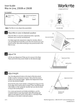
Installation
Before you can use your device or see its status, you need to install the software
application on your computer. Please do not plug in the device‘s USB cable to your
computer until after you have installed the software from the DVD.
1. Install the software application from the DVD onto your PC or Macintosh
®
computer.
2. Review all instructions in this Quick Start Guide before you start using your new
device. For more detailed information, please refer to Contents on the software DVD.
3. Remove the “Install software and read manual before first use” warning sticker from
the device.
4. After you have completed the software installation process, attach your i1Pro device
to your computer‘s USB port. If connected successfully both status indicators
light up solid white.
The X-Rite i1Pro will not work if it is connected to the USB port on your
keyboard or to a USB hub without external power supply.
i1Pro power rating: 5 V 500 mA.

EN
12 13
Device Status Indicators
The i1Pro device is equipped with two device status indicators on its top housing. The
device status indicators provide feedback on the current status of the device and guide
you through the measurement process.
General device status:
off The device is either not connected to your computer, the software
is not running, or the latest software to control the device is not
installed on your computer. In the third case, the device can still
be used in compatibility mode with software supporting older
revisions of the i1Pro device.
solid white The device is connected but needs calibration.
pulsating white The device is connected and ready for measurement.
solid red The calibration of the device failed due to a hardware problem (see
troubleshooting section for further information).
To avoid interference of the device status indicators with the measurement process, the
device status indicators are switched off during measurement.

EN
14 15
Calibrating the Device
Before you start measuring, please calibrate the device. If you own multiple devices
make sure that the serial number on the back of the calibration plate matches the serial
number of your i1Pro device. Refer to the user guide of your measurement software for
additional information on the calibration process.
1. In the center of the calibration plate is a slider to protect the white calibration tile.
Open this protective slider until it clicks into place to access the white reference
ceramic tile on this calibration plate.
2. Place the i1Pro measurement device on the calibration plate. The device must seat
firmly on the calibration plate.
3. Set the software for calibration of the device and press the measurement button.
Status indicator lights switch off during calibration. Once the device is successfully
calibrated the status indicator lights pulsate white. If the calibration fails the
status indicator lights will pulsate red and then return to solid white.
4. When the calibration is finished you should close the protective slider for the white
reference ceramic tile.
A clean white reference ceramic tile is essential for providing accuracy of
your measurements. The protection cover should always be closed when the
white reference ceramic tile is not in use. If necessary you can clean the white
reference ceramic tile with isopropyl alcohol and a soft clean cloth.

EN
16 17
Scan Measurement
Measurement conditions
The i1Pro measurement device is equipped with a fixed UVcut filter and supports only a
single measurement condition.
Single Pass Measurement is required for measurement condition
• ISO 13655 M2 | Illumination with UV excluded (UVcut)
The Status Indicators on the i1Pro device guides you through the measurement
process.
Virtual aperture technology
During a scan measurement the i1Pro device is performing 200 measurements per
second. The automatic patch detection of the device identifies useable measurements
made on a patch and unusable measurements made between two patches. Valid
measurements on a patch are averaged and the device reports the averaged result to
the software. Thanks to this technology the virtual aperture of the i1Pro device adapts to
the length of a patch. For best measurement results the length of the patches on your
test chart should be selected based on the resolution of your printer. For printers with
lower resolution or a grainy screening you should increase the length of the patches on
your test chart.

EN
18 19
Scan Measurement
To prepare your i1Pro device for a scan measurement you need to mount the i1Pro
device on the ruler. Make sure your device is calibrated and the status indicators
are pulsating white before you mount it.
1. Unfold the backup board.
2. Use the clamp to secure the test chart on the backup board.
3. Place the ruler on the backup board.
4. Position the i1Pro device in the carriage on the ruler. Make sure that the positioning
pins on the carriage slide into the reference gaps on the bottom of the i1Pro device.
Double-check that the i1Pro device seats firmly in the carriage.
5. During scanning measurement make sure that the device’s limiting aperture glides
smoothly on the guide rail of the ruler.
The distance between the i1Pro device and the surface of the printing substrate
is critical for the accuracy of your measurements. If the limiting aperture of the
device or the edge of the ruler‘s guide rail is worn out you should replace them.
Spare parts can be ordered through X-Rite‘s Service Centers.

EN
20 21
Single Pass Scan Measurement
2x green flash the row was measured successfully.
2x red flash the row was not measured successfully because not all patches
could be recognized. Measure the row again, but reduce your
measurement speed and make sure that the device starts and
ends the measurement before and after the patches of the test
chart.
4x red flash the row was not measured successfully because you started
reading the patches too early without giving the tungsten filament
lamp enough time to warm up. Measure the row again but allow
the lamp time to heat up before you start moving the i1Pro device.
1x green;
2x red flash the row was measured successfully but the software expected the
measurement of a different row. Check if the row you measured is
the row the software is expecting.
5. Position the ruler with the device in front of the next row of your test chart and
measure the next row.
1. Make sure that your device is calibrated and the status indicators are pulsating
white.
2. Position the ruler with the device on the white paper in front of row #1 of your test
chart. It does not matter if you scan the row from left to right or right to left.
3. Set your software to single scanning mode.
4. Press the measurement button on the device and wait one second before you start
moving the device to the opposite site on the ruler. Hold the measurement button
pressed until you have reached the far end of your test chart. The short delay before
the measurement process is required to warm up the tungsten filament lamp. The
status indicators on the device provides feedback if the measurement was
successful:

EN
22 23
Spot Measurement
To prepare your i1Pro device for spot measurement you need to mount the i1Pro device
on the positioning target. Make sure your device is calibrated and the status
indicators are pulsating white before you mount it. Refer to the user guide of your
measurement software for further details on the spot measurement process.
1. Mount the i1Pro measurement device on the positioning target by inserting the
mounting connector on the positioning target in the mounting interface at the rear of
the i1Pro device.
2. Configure your software to take spot measurements.
3. Position the device on the patch you would like to measure.
4. Press the measurement button on the device. Status indicator lights switch off
during a measurement and pulsate green once the measurement has been
successfully finished.
5. To remove the i1Pro device from the positioning target, gently pull the mounting
connector with the positioning target out of the mounting interface at the rear of the
i1Pro device.

EN
24 25
Display Measurement
To prepare your i1Pro device for a display measurement you need to mount the
i1Pro device on the display holder. Make sure your device is calibrated and the status
indicators are pulsating white before you mount it.
1. You can adjust the length of the counter weight of the display holder for the size
of your screen. The counter weight is equipped with hook-and-loop fasteners on
both ends which allow you to shorten and lengthen the display holder to the correct
length.
2. Mount the i1Pro measurement device on the display holder by inserting the
mounting connector on the display holder in the mounting interface at the rear of the
i1Pro device. Make sure that the nose of the i1Pro device seats firmly in the display
holder.
3. Fix the i1Pro measurement device in the middle of your screen.
4. Set the software for display measurement and start the measurement process in the
application. Status indicator lights switch off during measurement.
5. To remove the i1Pro device from the display holder, gently pull the mounting
connector with the display holder out of the mounting interface at the rear of the
i1Pro device.

EN
26 27
General Maintenance
To maintain the measurement performance of your i1Pro over its life time, it is important
to observe some rules and to periodically clean certain parts that are critical for
measurement performance.
• The i1Pro device is sensitive to mechanical shocks. To avoid damage during
transport the i1Pro must be always shipped in its original packaging.
• Do not store or operate the i1Pro device in dirty, greasy or dusty environments. Do
not use the i1Pro in environments with temperatures higher than 35°C (95ºF) or less
than 10°C (50ºF). Do not store the i1Pro in environments with temperatures higher
than 50°C (122ºF) or less than -10°C (14ºF).The plastic housing of the device may
be cleaned using a cloth dampened in water with a soap solution if necessary.
• The protection glass in the limiting aperture of the i1Pro device may become dusty
after some time. You can remove the protective glass to clean it and the inside of the
limiting aperture:
1. To remove the limiting aperture turn it clockwise until the arrow points to the
“unlocked” position on the i1Pro device.
2. Remove the limiting aperture from the device. Avoid touching the optics.
3. Slide the slider with the protection glass out of the limiting aperture.
4. Clean the protection glass and the inside of the limiting aperture with isopropyl
alcohol on a soft clean cloth.
5. Re-assemble the limiting aperture with the protection glass slider. Make sure
that the slider snaps back into its original position.
6. Mount the limiting aperture back on the device with the arrow pointing at the
“unlocked” position on the i1Pro device.
7. To lock the limiting aperture turn it counter-clockwise until the arrow points to
the “locked” position on the i1Pro device.
• Keep the white reference ceramic tile clean at all times. You can clean the white
reference ceramic tile with isopropyl alcohol on a soft clean cloth if required.

EN
28 29
Troubleshooting
Diagnostic Software
Use the i1Diagnostics software if you believe your i1Pro is not functioning properly.
In this case please perform the following steps:
1. Launch i1Diagnostics Software.
2. Perform a functionality check by following the instructions given from the
i1Diagnostics Software.
3. If i1Diagnostics software reports an error store the test report and contact your
nearest X-Rite Support Center. As an alternative you can also take a look at our
online support resources www.xrite.com/support/i1Profiler to troubleshoot your
issue.

EN
30 31
Warranty
WARRANTY REGISTRATION
To receive technical support, obtain warranty service, and get the latest software updates and product news, register
your new i1Pro system: www.xrite.com/register.
WARRANTY CONDITIONS
X-Rite warrants that this product against defects in material and workmanship for a period of twelve (12) months from
the date of sale, unless different local regulations apply. During such time X-Rite will either replace or repair at its
discretion defective parts free of charge. (Consumable parts are not covered.) This warranty shall not apply to any goods
supplied hereunder which after shipment are damaged, altered in any respect, or subjected to negligent treatment.
X-Rite‘s sole and exclusive obligation for breach of the above warranties shall be the repair or replacement of any part,
without charge, which within the warranty period is proven to X-Rite‘s reasonable satisfaction to have been defective.
Repairs or replacement by X-Rite shall not revive an otherwise expired warranty, nor shall the same extend the duration
of a warranty. X-Rite shall in no event be liable for losses or costs to Buyer in manufacturing, or for Buyer‘s overhead,
other expenses, lost profits, goodwill, or any other special, indirect, consequential, incidental or other damages to
persons or property resulting from a breach of any of the foregoing warranties. There are no other warranties, either
express or implied, which extend beyond the warranties set forth herein. The express warranties contained herein are
in lieu of all other warranties, express or implied, including, but not limited to, the implied warranty or merchantability
and fitness for a particular purpose or application. No representations or statements not expressly set forth herein shall
be binding upon X-Rite as a warranty or otherwise. To obtain warranty service, you must take the Product, or deliver
the Product freight prepaid, in either its original packaging or packaging affording an equal degree of protection, to an
authorized X-Rite service center. Proof of purchase in the form of a bill of sale or receipted invoice which is evidence
that the unit is within the Warranty period must be presented to obtain warranty service.
Do not try to dismantle the X-Rite i1Pro for any reason. Unauthorized dismantling of the equipment will void all warranty
claims. Contact the X-Rite Support or the nearest X-Rite Service Center, if you believe that the unit does not work
anymore or does not work correctly.
Service and Support
RECERTIFICATION
X-Rite recommends an annual recertification of i1Pro spectrophotometer. Contact your X-Rite dealer or the nearest
X-Rite Service Center to find out more about recertification.
SERVICE CENTERS
Visit our i1Pro website at www.xrite.com to locate the nearest X-Rite Service Center or contact your X-Rite dealer for
more information.
SUPPORT OPTIONS
We are confident you will be pleased with your new X-Rite product. At the same time, we understand your need for
on-demand support and training in today’s complex and rapidly evolving workflows. Because of this we are making the
following on-line and free support tools available to registered users.
These support tools are found at: www.xrite.com/support/i1Profiler
• Free and unlimited access to the i1Proler interactive training video; available within the i1Proler software too.
• Free and unlimited access to the X-Rite on-line Help Desk, which includes detailed and helpful support articles
related to frequently asked questions.
• Free access to X-Rite’s e-mail support and call center during the warranty period for issues resulting from general
product use provided:
- You are the original registered user of the product
- You are using the current version of i1Profiler software
- You are using currently supported hardware and supported platform (operating system)
Because we recognize the need for advanced support related to using i1Profiler and X-Rite products in various
workflows, as well as support in post warranty time periods, we are happy to offer fee based support programs and
training options delivered by X-Rite’s highly experienced Color Experts.
For complete information, please visit www.xrite.com/i1Profiler/Supportoptions

EN
32 33
Specification
Spectral
engine:
i1
®
technology (holographic diffraction grating with 128 pixel diode array)
Spectral range: 380 - 730 nm
Physical sampling interval: 3.5 nm
Optical resolution: 10 nm
Spectral reporting: 380 nm ... 730 nm in 10 nm steps
Measurement frequency in scanning
mode: 200 measurements per second
Optics:
Measurement geometry: 45º/0º ring illumination optics, ISO 13655:2009
Measurement aperture: 4.5 mm (0.18”) diameter
(effective measurement aperture during scanning is depending on the
patch size and measurement speed)
Illumination spot size: 3.5 mm (0.14”)
Light source: Gas filled Tungsten (illuminant type A)
Reflectance
measurement: spectral reflectance [dimensionless]
Measurement condition: UV excluded Filter - ISO 13655:2009 measurement condition M2
:
Calibration: Manual on external ceramic white reference
Measurement background: white, ISO 13655:2009; for measurements on backup board
Maximal media thickness: 3 mm (0.12”) on backup board
Minimal patch size in scanning mode: 10 x 10 mm (0.39” x 0.39”) (Width x Height)
Inter-Instrument-Agreement: 0.4 ∆E94* average, 1.0 ∆E94* max.
(deviation from X-Rite manufacturing standard at a temperature of 23ºC
(73.4ºF) on 12 BCRA tiles (D50, 2º))
Short-term repeatability: 0.1 ∆E94* on white (D50,2°, mean of 10 measurements every 3 s on
white)
Emission
measurement: spectral radiance [mW/nm/m
2
/sr], luminance [cd/m
2
]
Measurement range: 0.2 - 1200 cd/m
2
on a typical LCD-Monitor
Short-term repeatability: x,y ±0.002 typ. (5000 K, 80 cd/m
2
)
Ambient light
measurement:
spectral irradiance [mW/nm/m
2
], illuminance [lux]
cosine corrected diffusor light measurement head
Interface:
USB 1.1

DE
Minimum System Requirements
34 35
Minimum System Requirements
Macintosh
®
Intel
®
CPU, Mac OS X 10.5.8, 10.6.8 or 10.7 (with latest upgrades installed), 1 GB of available RAM, 2 GB of available
hard disk space, monitor resolution of 1024 x 600 pixels or higher, powered USB port, DVD drive or high speed internet
connection to download, install and update the software. Dual display support requires either 2 video cards or a dual
head video card that supports dual video LUTs being loaded. User must have Administrator rights to install and uninstall
the application.
Windows
®
Intel
®
Pentium
®
4 or AMD Athlon XP™ or better CPU, Microsoft
®
Windows
®
XP
®
, Windows Vista®, Windows 7
®
(all
32 or 64-bit and with latest service packs installed), 1 GB of available RAM, 2 GB of available hard disk space, monitor
resolution of 1024 x 600 pixels or higher, powered USB port, network adaptor installed and driver loaded, DVD drive
or high speed internet connection to download, install and update the software. Dual display support requires either 2
video cards or a dual head video card that supports dual video LUTs being loaded. User must have Administrator rights
to install and uninstall the application.
Important note
The X-Rite i1Pro instrument can be used with older versions of the i1Pro software development kit (SDK) which were
developed for older revisions of the i1Pro. In this case the new i1Pro operates in a downwards compatibility mode as
an ISO 13655 measurement mode M2 (UVcut Filter) device and new functions like the status indicator lights won‘t be
operational. To make use of the complete functionality of this instrument check with your software supplier if newer
versions of your software with the latest SDK are available.
EN
Benutzerhandbuch
Inhaltsverzeichnis
Lieferumfang 36
Geräteübersicht 38
Installation 40
Gerätestatusanzeige 42
Gerätekalibrierung 44
Streifenmessung 46
Streifenmessung 48
Einfache Streifenmessung 50
Einzelmessung 52
Monitormessung 54
Allgemeine Wartung 56
Fehlerbehebung 58
Garantie und Gewährleistung 60
Service und technischer Kundendienst 61
Technische Daten 62
Minimalvoraussetzungen 64

DE
38 39
Geräteübersicht
Spectrophotometer
1
2
3
4
5
6
7
Spektralfotometer
Limiting Aperture
Measurement Button
Status Indicators
Type Label with Serial Number
1
2
3
4
5
6
7
Reference Gap for Ruler Mount
Mounting Interface for Accessories
USB Connector
Tubus
Messtaste
Statusanzeige
Typenschild mit Seriennummer
Referenzpunkte für Linealbefestigung
Anschlussstelle für Zubehör
USB-Verbindung

PT
158 159
Visão Geral do Dispositivo
Spectrophotometer
1
2
3
4
5
6
7
Espectrofotômetro
Limiting Aperture
Measurement Button
Status Indicators
Type Label with Serial Number
1
2
3
4
5
6
7
Reference Gap for Ruler Mount
Mounting Interface for Accessories
USB Connector
Abertura de Medição
Botão de Medição
Indicadores de Estado
Etiqueta de Tipo com Número de Série
Espaço de Referência para a Montagem em Esquadro
Interface de Montagem para Acessórios
Conector USB

JP
188 189
Limiting Aperture
Measurement Button
Status Indicators
Type Label with Serial Number
1
2
3
4
5
6
7
Reference Gap for Ruler Mount
Mounting Interface for Accessories
USB Connector
測定アパーチャー
測定ボタン
ステータスインジケータ
モデル名、シリアル番号の表示ラベル
ルーラー取付用リファレンスギャップ
アクセサリ取付用インターフェース
USBコネクタ
Spectrophotometer
1
2
3
4
5
6
7
分光測色計
装置の概要
/