Page is loading ...

1
SLIDE AN
Rev.01 - 04/2016
Sistemi Elettronici
di Apertura Porte e Cancelli
International registered trademark n. 804888
®
SEA S.p.A.
Zona industriale 64020 S.ATTO Teramo - (ITALY)
Tel. +39 0861 588341 r.a. Fax +39 0861 588344
www.seateam.com
67411975
Italiano
CENTRALE DI COMANDO PER CANCELLI SCORREVOLI, SINGOLA ANTA BATTENTE, BARRIERE E PORTE DA GARAGE
CONTROL UNIT FOR SLIDING GATES, SWING SINGLE LEAF, BARRIERS AND GARAGE DOORS
ARMOIRE DE COMMANDE POUR PORTAILS COULISSANTS, UN VANTAIL BATTANT, BARRIERES ET PORTES DE GARAGE
CENTRAL ELECTRÓNICA PARA CANCELAS CORREDIZAS, HOJA INDIVIDUAL ABATIBLE, BARRERAS Y PUERTAS BASCULANTES
English
Français
Español

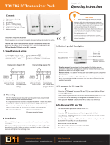
CN1 = inputs / outputs connector
CN2 = Clean contact connector
CN3 = Motor and light connector
CN4 = Power Connector
CNA = UNI receiver connector
CNS = RF FIX receiver connector
CNP = Programming connector
TR1 = Work time Trimmer
TR2 = Motor torque trimmer
Tr3 = Pause time trimmer
P1 = Transmitter programming button
T1 = Triac motor drive
R1 = Motor control / courtesy light relay
R2 = Motor exchange relay
R3 = 1A Dry contact relay
F1 = 6.3AT fuse on 230V - 10AT on 115V
TR = Power Transformer
DS = Dip switches logics and photocells
L1 = Transmitters programming LED
RX RECEIVER
COMPONENTS DESCRIPTION
TECHNICAL SPECIFICATIONS
Control unit power supply: 230 Vac 50/60 Hz - 115Vac 50/60 Hz
Absorption in stand by: 30 mA
Environment temperature : -20°C +50°C
Specifications of external enclosure: 183 X 238 X 120 - Ip55
TR
CN1
CNA
R1
R2
CNP
T1
F1
CNS
CNS
144 mm
85 mm
ON ON
ON ON
CN2
4
3
2
1
R3
L1
DS
P1
TR1 TR2 TR3
Sistemi Elettronici
di Apertura Porte e Cancelli
®
SLIDE AN
English
English
10
CN4
CN3

CN4
CN2
L
20
N
21
Line
Neutral
Not connected
Start
Stop
Common
Antenna
Ped. START
Common
Common
Limit switch opneing
Limit switch closing
Common
Edge 1
Coil - Photocell
CNS
RF FIX RADIO MODULE
RF FIX
receiver
connector
DRY CONTACT 1A
(Available from
hardware revision R1)
Light
Motor 1 opening
Motor 1 closing
Motor 1 Neutral
14
17 16
15
CN3
M1
LIGHT MOP MN MCL
1
2
3 4
5 6
7 8
9
10
11
12
13
CN1
ANT COM
START
PEDST
STOP COM PH
EDGE
COM
LSO
LSC
24Vac 200mA
JUMPER NEEDED ON N.C. CONTACTS
DIP SWITCH ADJUSTMENT
ATTENTION: Bridge the N.C. Inputs which are not used, except of the limit switches
(Photocell, STOP and Edge) .
N.C. Contacts
24Vac
CNA
RF RADIO MODULE
(UNI SERIES)
Active for a second
at every start impulse
CONNECTIONS
1
2
3
4
Logic choice
Photocell function
DIP
Mode1
Mode4
Mode2
Mode3
1 / 2
OFF / OFF
ON / OFF
FONCTION
STEP STEP 1
AUTOMATIC
DIP
1 / 2
1 / 2
OFF / ON
ON / ON
2 BUTTONS
DEADMAN
1 / 2
1 / 2
3 / 4
OFF / OFF
ON / OFF
FONCTION
PHOTOCELL ONLY CLOSING
DIP
1 / 2
1 / 2
OFF / ON
ON / ON
PHOTOCELL RESETS PAUSE
PHOTOCELL OPENING AND CLOSING
1 / 2
1 / 2
PHOTOCELL RECHARGES PAUSE
Sistemi Elettronici
di Apertura Porte e Cancelli
®
SLIDE AN
English
English
11

A) 24V ac ~ max 200mA 8
PHOTOCELL (COIL)
1 2 3 4 5 6 7 8
RX1
C
CN1
6
9 10 11 12 13
7
TX1
-
-
+
8
8
9
9
SAFTY EDGE CONNECTION
CONNECTIONS
SAFETY DEVICES
If the photocell is engaged during opening, pause or closing, the gate opens
completely and it closes again without respecting the pause time.
Pause reset 1 ON / 2 ON
Pause recharge 1 OFF / 2 ON
The photocell recharges the pause time
If the photocell is engaged during closing it inverts the movement
Opening 1 ON / 2 OFF
Photocell is active during opening and closing. If the photocell is committed
during opening, the gate stops, when released the gate continues the
opening. In closing the gate stops and when released it goes back to opening.
Closing 1 OFF / 2 OFF
PHOTOCELL (COIL) OPTIONS
It is possible to connect the safety edge (EDGE)
between contacts 9 and 10 of CN1.
If it’s squeezed, the contact opens causing a partial
inversion of the mouvement.
Note 1: Bridge the edge contact if not used
10 11 12 13
1 2 3 4 5 6 7 8 9
CN1
Closing
safety edge
C
10
9
24Vac (8) COM (-)= 0V (9) PH (C)= Photocell contact (7)
The photocell can be configured as: closure only, opening and closing,
pause recharging and reset pause
Note: Brigde the photocell contact if not used.
Sistemi Elettronici
di Apertura Porte e Cancelli
®
SLIDE AN
English
English
SAFETY EDGE 9 and 10
12

Function 1 (STANDARD): pedestrian opening will be 50% of the set working time
• Function 2 (TIMER): holding the pedestrian start the gate opens and remains open.
When released the gate repeats the selected pause and starts closing. In the case in
which a security is activated, the timer automatically resets after 6 seconds ( f
function active only in automatic logic)
• Function 3 (2 BUTTONS: in "2 buttons" logic press the pedestrian start to close the
gate.
• Function 4 (DEADMAN): in "deadman" logic the pedestrian start will execute the
closing if kept pressed.
Function 1 (STANDARD): If a pulse is sent to
this input it determines the opening / closing of the
automation depending on the selected logic.
• Function 2 (TIMER): The hold START triggers the TIMER function, when the start is released it the automation
repeats the pause time and then performs the closing. To connect the supplied devices (such as the coil) please
see the specific instructions. In case of intervention of a safety device the timer will automatically reset after 6 s.
• Function 3 (2 BUTTONS): In 2 BUTTONS logic it performs the opening (function only active in automatic logic)
• Function 4 (DEADMAN): In DEADMAN logic START must be pressed for the opening of the automation.
START (N.O.) 3
CONNECTIONS
PARTIAL OPENING, STOP, START
PARTIAL OPENING (N.O.) 4
When pressing this button the motor immediately stops in any
condition/position.
To re-start the movement give a start command. After a stop the motor
always re-starts in closing.
Note: Bridge the STOP contact if not used.
STOP (N.C.) 5
10 11 12 13
1 2 3 4 5 6 7 8 9
CN1
3
6
5
6
STOP
6
4
C
START
-
ANTENNA
PARTIAL
OPENING
If not connected they must not be bridged.
For the limit switch function, limit switches are required in both
opening and closing.
For the correct operation of the limit switch there must be
correspondence between the direction of motor and the respective
engaged limit switch.
Com = Common
C= Contact
If not connected they must not be bridged.
For the limit switch function, limit switches are required in both
opening and closing.
For the correct operation of the limit switches there must be
correspondence between the direction of motor and the respective
engaged limit switches.
Com = Common
C= Contact
NOTE: WARNING CONTACT NORMALLY OPEN
!
LIMIT SWITCH 11 12 13
LIMIT SWITCH 11 12 13
MECHANICAL LIMIT SWITCHES
CONNECTION
MAGNETIC LIMIT SWITCHES
CONNECTION
1 2 3 4 5 6 7 8
9 10 11 12 13
N.O.
N.O.
1
3
1
1
11
12
Limit switch
closing
Limit switch
opening
N C C
1 2 3 4 5 6 7 8
9 10 11 12 13
N.C.
N.C.
1
3
1
1
11
12
Limit switch
closing
Llimit switch
opening
N C C
CN1
CN1
To enable the control unit to function with magnetic limit switches it must
be turned on by keeping pressed P1 for 5 s. The correct setting will be
indicated by three slow flashes of L1.
4 slow flashes indicate, instead, mechanical limit switch.
Sistemi Elettronici
di Apertura Porte e Cancelli
®
SLIDE AN
13

COURTESY LIGHT, MOTORS, CAPACITY
AND POWER SUPPLY CONNECTIONS
COURTESY
LIGHT
Capacitor
Motor
Motor connection
M = Opening /Closing
Com = COMMON
Example
POWER SUPPLY INPUT
NOTE: For power supply connection follow the rules in force
Active only during cycle
(max 50W)
M
Opening
CN2
N L
CN3
Neutral
Closing
Neutral
16
14
16
15
14
17 16 15 14
17
15
Line
Sistemi Elettronici
di Apertura Porte e Cancelli
®
SLIDE AN
English
English
14
Note: to have the
flashing function it is
necessary to add the
YGO flash card.

A) AUTOMATIC
A start command opens the gate. A second pulse while opening is not accepted.
A start command during closing inverts the movement.
NOTE 1: In order to have the automatic closing it is necessary to set a pause time, otherwise all the logics will be
semiautomatic. With pause trimmer turned fully counterclockwise the logic will be semiautomatic and a Start pulse is
necessary for reclosing.
B) STEP BY STEP TYPE1
The start command follows the logic OPEN-STOP-CLOSE-STOP-OPEN
NOTE 1: In order to have the automatic closing it is necessary to set a pause time, otherwise all the logics will be
semiautomatic
NOTE 1: In order to have the automatic closing is necessary to set a pause time, otherwise all the logics will be
semiautomatic. With the pause Trimmer turned fully counterclockwise the logic will be semiautomatic, and a Start
pulse is necessary for reclosing.
C) DEADMAN
The gate will open as long as the Start opening button is hold; when released the gate stops. The gate closes as long
as the button which is connected to the pedestrian Start is hold; when released the gate stops. To execute complete
opening and/or closing cycles keep the related buttons constantly pressed.
D) 2 BUTTONS
One Start pulse opens, one pedestrian start closes. In opening the closing command is it is not accepted. In closing a
start command reopens, a pedestrian start command (close) is ignored.
OPERATING LOGICS
AUTOMATION START
1) Unlock the gate and put it halfway.
2) If limit switches are present give a start and verify the correspondence between the direction of movement and
correct limit switch activation. If the movement is not correct exchange the direction of the limit switches and / or of the
motor or of both. If no limit switches are present the moving time will be related with the Tr1 trimmer working time setting
and slowdown is not possible.
3) Adjust the working time trimmer so that the movement reaches the stop and / or the limit switches. In installations
with limit switches it is possible to have the slowdown depending on how the working time TR1 trimmer has been set.
To fully exclude the slowdown turn the working time trimmer completely clockwise.
TRIMMER ADJUSTMENTS
TR 1= WORK TIME
TR 2 = MOTOR TORQUE
Adjsuts the working time from 10 seconds to 2 minutes. If
turned completely clockwise you will have maximum
working time and all slowdowns will be excluded.
Adjusts the motor operating torque. Turned completely
clockwise it will give the max. Torque.
TR 3 = PAUSE TIME
Adjusts pause time from 0 to 2 minutes. If turned
completely counterclockwise the pause time will be 0 and
the operating logics will become semi-automatic.
TR1 max = slowdown OFF
Min
Max
Min
Max
Min
Max
TRIMMER ADJUSTMENT
FUNCTION
TR3 min = Semiautomatic logic
Sistemi Elettronici
di Apertura Porte e Cancelli
®
SLIDE AN
English
English
15

RF FIX RECEIVER ON BOARD OF CONTROL UNIT
!
Connect the receiver
on the CNS connectors,
ensuring that the
verse is the one
indicated in the FIG.
UNI SERIES RECEIVERS ON BOARD OF CONTROL UNIT
!
RF UNI
16 USERS without memory
800 USERS with MEMO additional memory
RF UNI PG
100 USERS Fixed code
800 USERS Roll Plus
RF UNI PG
800 USERS fixed code
800 USERS Roll Plus
Old model without additional memory
New model with MEMO additional memory
ATTENTION: Do the remote controls programming before connecting the antenna and inserting the receiver into
the CNA connector (if available) with control unit off.
With the RF UNI and RF UNI PG modules it is possible to use radio transmitters of Roll Plus series as well as radio transmitters with
fixed code. The first stored radio transmitter determines the type of the remaining radio transmitters.
In the case in which the receiver has rolling code, it is necessary to push twice the button of the radio transmitter to be programmed for storing
the first transmitter.
In the case in which the radio control has fixed code, it is necessary to push 1 time the button of the radio transmitter to be programmed to store
the first transmitter.
Notes:
- Do the learning of the transmitter only with stopped cycle and closed gate. START and PEDESTRIAN START can be stored. If the received
code had already been assigned the transmitter will be deleted.
RADIO CONTROLS SELFLEARNING
PROGRAMMING OF START CONTROL:
Press P1, L1 LED turns on, send from the transmitter the button to be stored and the LED L1 turns off for 1 second and turns on again waiting
for a new command. If the same button is transmitted twice the same will be deleted. Press P1 twice to exit programming (L1 off)
PROGRAMMING OF PEDESTRIAN START :
Press P1 twice L1 LED flashes rapidly, transmit from the transmitter the button to be stored as pedestrian start LED L1 turns off for 1 second
and returns to flash waiting for a new command. If the same button is transmitted twice tthe same will be deleted. Press P1 once to exit
programming (L1 off)
CANCELLATION OF ALL TRANSMITTERS:
Press and hold P1 for 5 seconds LED L1 will TURN ON and then will issue 6 flashes to confirm the cancellation.
ATTENTION: Perform the remote controls programming before connecting the antenna and inserting the
receiver into the CNS connector (if available) with control unit switched off.
With the RF FIX module it will be possible to use only remote controls with a fixed code.
Notes:
- You can store up to a maximum of 16 remote controls (buttons).
- It is possible to store for each remote control a start button and one for pedestrian start. If the received radio control had already
been assigned it will be canceled.
CANCELLATION OF ALL TRANSMITTERS:
Press and hold P1 for 5 seconds LED L1 will TURN ON and then will issue 6 flashes to confirm the cancellation.
Sistemi Elettronici
di Apertura Porte e Cancelli
®
SLIDE AN
English
English
16

a.) Relock the motor
b.) Remove the obstacle
b.) Too low working time
b.) Increase the working time through
Trimmer TR1
c.) Increase the torque parameter through
Trimmer TR2.
a.) b.) c.) Check the jumpers or the
condition of the linked
accessories.
b) Decrease the value of the pause
trimmer
a.) Adjust the pause time different form 0
a.) Jumper missing on one of the N.C.
Contacts
b.) Burnt fuse
Motor doesn’t respond to any
START impulse
a.) Check the connections or the jumpers on the
connections of the safety edge, of the stop and
of the photocell
b.) Replace the burned fuse on the control unit
Advises
Make sure all Safeties are turned ON
All N.C. contacts must have jumpers
Problem Found Possibile Cause Solutions
Gate doesn’t move while the
motor is running
Gate doesn’t reach the complete
Open / Closed position
The gate opens but doesn’t
close
The gate doesn’t close
automatically
a.) The motor is in the released position
b.) There is an obstacle
a.) Wrong setting of the limit switches
c.) Torque too low
a.) Set limit switches
a.) Pause time set to high
b.) Control unit in semi-autom. logic
a.) The contacts of the photocell are open.
b.) The stop contact is open
c.) The edge contact is open
Page for both installer and user
WAREHOUSING TEMPERATURES
T
min
T
Max
Dampness
min
Dampness
Max
5% Not condensing 90% Not condensing
MAINTENANCE
Considering the number of working cycles and the kind of gate, if the gate has changed the clutches and doesn’t work it’s necessary to
periodically proceed, with the learning times reprogramming on the electronic control unit.
Periodically clean the optical systems of the photocells.
REPLACEMENTS
Any request for spare parts must be sent to:
SEA S.p.A. - Zona Ind.le, 64020 S.ATTO - Teramo - Italia
SAFETY AND ENVIRONMENTAL COMPATIBILITY
Disposal of the packaging materials of products and/or circuits should take place in an approved disposal facility.
REGULAR PRODUCT DISPOSAL (electric and electronic waste)
(It’s applicable in EU countries and in those ones provided with a differential waste collection)
The brand that you find on the product or on documentation signals that the product must not be disposed off together with other domestic
waste at the end of life cycle. In order to avoid any possible environmental or health damage caused by irregular waste disposal, we
recommand to separate this product from other forms of waste and to recycle it in a responsible way in order to provide the sustainable re-use of
material resources. Domestic users are invited to contact the retailer where the product has been purchased or the local office in charge of all
the information related to differential watse collection and recycling of this kind of product.
STORING
Materials handling must be made with appropriate vehicles.
WARRANTY LIMITS
For the guarantee see the sales conditions on the official SEA price list.
SEA reserves the right to make any required modification or change to the products and/or to this manual without any advanced notice
obligation.
- 20°C + 65°C
TROUBLE SHOOTING
Sistemi Elettronici
di Apertura Porte e Cancelli
®
SLIDE AN
English
English
17

TERMS OF SALES
EFFICACY OF THE FOLLOWING TERMS OF SALE: the following general terms of sale shall be applied to all orders sent to SEA S.p.A.
All sales made by SEA to all costumers are made under the prescription of this terms of sales which are integral part of sale contract and
cancel and substitute all apposed clauses or specific negotiations present in order document received from the buyer.
GENERAL NOTICE The systems must be assembled exclusively with SEA components, unless specific agreements apply. Non-
compliance with the applicable safety standards (European Standards EM12453 – EM 12445) and with good installation practice
releases SEA from any responsibilities. SEA shall not be held responsible for any failure to execute a correct and safe installation under
the above mentioned standards.
1) PROPOSED ORDER The proposed order shall be accepted only prior SEA approval of it. By signing the proposed order, the Buyer
shall be bound to enter a purchase agreement, according to the specifications stated in the proposed order.
On the other hand, failure to notify the Buyer of said approval must not be construed as automatic acceptance on the part of SEA.
2) PERIOD OF THE OFFER The offer proposed by SEA or by its branch sales department shall be valid for 30 solar days, unless
otherwise notified.
3) PRICING The prices in the proposed order are quoted from the Price List which is valid on the date the order was issued. The discounts
granted by the branch sales department of SEA shall apply only prior to acceptance on the part of SEA. The prices are for merchandise
delivered ex-works from the SEA establishment in Teramo, not including VAT and special packaging. SEA reserves the right to change at
any time this price list, providing timely notice to the sales network. The special sales conditions with extra discount on quantity basis (Qx,
Qx1, Qx2, Qx3 formula) is reserved to official distributors under SEA management written agreement.
4) PAYMENTS The accepted forms of payment are each time notified or approved by SEA. The interest rate on delay in payment shall be
1.5% every month but anyway shall not be higher than the max. interest rate legally permitted.
5) DELIVERY Delivery shall take place, approximately and not peremptorily, within 30 working days from the date of receipt of the order,
unless otherwise notified. Transport of the goods sold shall be at Buyer’s cost and risk. SEA shall not bear the costs of delivery giving the
goods to the carrier, as chosen either by SEA or by the Buyer. Any loss and/or damage of the goods during transport, are at Buyer’s cost.
6) COMPLAINTS Any complaints and/or claims shall be sent to SEA within 8 solar days from receipt of the goods, proved by adequate
supporting documents as to their truthfulness.
7) SUPPLY The concerning order will be accepted by SEA without any engagement and subordinately to the possibility to get it’s supplies
of raw material which is necessary for the production; Eventual completely or partially unsuccessful executions cannot be reason for
complains or reservations for damage. SEA supply is strictly limited to the goods of its manufacturing, not including assembly, installation
and testing. SEA, therefore, disclaims any responsibility for damage deriving, also to third parties, from non-compliance of safety
standards and good practice during installation and use of the purchased products.
8) WARRANTY The standard warranty period is 12 months. This warranty time can be extended by means of expedition of the warranty
coupon as follows:
SILVER: The mechanical components of the operators belonging to this line are guaranteed for 24 months from the date of
manufacturing written on the operator.
GOLD: The mechanical components of the operators belonging to this line are guaranteed for 36 months from the date of manufacturing
written on the operator.
PLATINUM: The mechanical components of the operators belonging to this line are guaranteed for 36 months from the date of
manufacturing written on the operator. The base warranty (36 months) will be extended for further 24 months (up to a total of 60 months)
when it is acquired the certificate of warranty which will be filled in and sent to SEA S.p.A. The electronic devices and the systems of
command are guaranteed for 24 months from the date of manufacturing. In case of defective product, SEA undertakes to replace free of
charge or to repair the goods provided that they are returned to SEA repair centre. The definition of warranty status is by unquestionable
assessment of SEA. The replaced parts shall remain propriety of SEA. Binding upon the parties, the material held in warranty by the
Buyer, must be sent back to SEA repair centre with fees prepaid, and shall be dispatched by SEA with carriage forward. The warranty
shall not cover any required labour activities.
The recognized defects, whatever their nature, shall not produce any responsibility and/or damage claim on the part of the Buyer against
SEA. The guarantee is in no case recognized if changes are made to the goods, or in the case of improper use, or in the case of tampering
or improper assembly, or if the label affixed by the manufacturer has been removed including the SEA registered trademark No. 804888.
Furthermore, the warranty shall not apply if SEA products are partly or completely coupled with non-original mechanical and/or electronic
components, and in particular, without a specific relevant authorization, and if the Buyer is not making regular payments. The warranty
shall not cover damage caused by transport, expendable material, faults due to non-conformity with performance specifications of the
products shown in the price list. No indemnification is granted during repairing and/or replacing of the goods in warranty. SEA disclaims
any responsibility for damage to objects and persons deriving from non-compliance with safety standards, installation instructions or use
of sold goods. The repair of products under warranty and out of warranty is subject to compliance with the procedures notified by SEA.
9) RESERVED DOMAIN A clause of reserved domain applies to the sold goods; SEA shall decide autonomously whether to make use of
it or not, whereby the Buyer purchases propriety of the goods only after full payment of the latter.
10) COMPETENT COURT OF LAW In case of disputes arising from the application of the agreement, the competent court of law is the
tribunal of Teramo. SEA reserves the faculty to make technical changes to improve its own products, which are not in this price list at any
moment and without notice. SEA declines any responsibility due to possible mistakes contained inside the present price list caused by
printing and/or copying. The present price list cancels and substitutes the previous ones. The Buyer, according to the law No. 196/2003
(privacy code) consents to put his personal data, deriving from the present contract, in SEA archives and electronic files, and he also
gives his consent to their treatment for commercial and administrative purposes.
Industrial ownership rights: once the Buyer has recognized that SEA has the exclusive legal ownership of the registered SEA brand
num.804888 affixed on product labels and / or on manuals and / or on any other documentation, he will commit himself to use it in a way
which does not reduce the value of these rights, he won’t also remove, replace or modify brands or any other particularity from the
products. Any kind of replication or use of SEA brand is forbidden as well as of any particularity on the products, unless preventive and
expressed authorization by SEA.
In accomplishment with art. 1341 of the Italian Civil Law it will be approved expressively clauses under numbers:
4) PAYMENTS - 8) GUARANTEE - 10) COMPETENT COURT OF LOW
Sistemi Elettronici
di Apertura Porte e Cancelli
®
SLIDE AN
35

Questo articolo è stato prodotto seguendo rigide procedure
di lavorazione ed è stato testato singolarmente al fine di
garantire i più alti livelli qualitativi e la vostra soddisfazione.
Vi ringraziamo per aver scelto SEA.
This item has been produced following strict production
procedures and has been singularly tested for the highest
quality levels and for your complete satisfaction.
Thanks for choosing SEA.
Cet article a été produit suivant des procédures d'usinage
strictes et il a singulièrement été testé afin de garantir
les plus hauts niveaux de qualité pour votre satisfaction.
Nous vous remercions d'avoir choisi SEA.
Este articulo ha sido producido siguiendo rigidos
procedimientos de elaboracion y ha sido probando
singolarmente a fin de garantizar los mas altos inveles de
calidad y vuestra satisfaccion.
Le agradecemos por haber escogito SEA.

Sistemi Elettronici
di Apertura Porte e Cancelli
International registered trademark n. 804888
®
SEA S.p.A.
Zona industriale 64020 S.ATTO Teramo - (ITALY)
Tel. +39 0861 588341 r.a. Fax +39 0861 588344
www.seateam.com
/