
240–34846 002
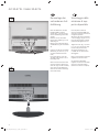
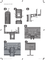
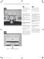
Floor Stand 8
Zubehör TV
Accessori TV
Toebehoren TV
Accessories TV
Accessoires TV
Accesorios TV
Floor Stand 8 32-40
Floor Stand 8 42-47
Montageanleitung, Istruzioni sul montaggio, Montage-instructis,
Installation Instructions, Instructions d´intallation, Instrucciones de montaje
34846_002_Floor Stand_8_08_02_2011_printer.indd 134846_002_Floor Stand_8_08_02_2011_printer.indd 1 08.02.2011 14:25:3308.02.2011 14:25:33

2
Floor Stand 8 32-40
Art. Nr. 69468B00
Floor Stand 8 42-47
Art. Nr. 69469B00
Printed in Germany LF 02.11
Änderungen vorbehalten.
Con riserva di modifi che.
Wijzigingen voorbehouden.
Subject to modifi cations.
Modifi cations reservée.
Reservado el drecho
a modifi caciones.
Deutschland
Loewe Opta GmbH
Customer Care Center
Industriestraße 11
D-96305 Kronach
D-96317 Kronach
Telefon 01801/22256393
Telefax (09261) 99500
34846_002_Floor Stand_8_08_02_2011_printer.indd 234846_002_Floor Stand_8_08_02_2011_printer.indd 2 08.02.2011 14:25:3508.02.2011 14:25:35
Page is loading ...

4
Floor Stand 8
Dear
customer,
Congratulations on your purchase of
this high quality product. For many years
Loewe has stood for innovative design,
excellent quality and functionality.
Please follow the installation and safety
instructions in this manual to ensure that
your product retains these properties for
many years to come.
Floor Stand 8 32-40
Art. No. 69468B00
can be used for the following TV sets:
Spheros R 32
Spheros R 37
Xelos A 32
Xelos A 37
Modus L 32
Modus L 37
Connect 32
Connect 37
Art 32 SL
Art 37 SL
Xelos 32 SL
Xelos 37 SL
Individual 32 LED
Individual 40 LED
Connect 32 LED
Connect 40 LED
Art 32 LED
Art 37 LED
Art 40 LED
Xelos 32 LED
Xelos 40 LED
Floor Stand 8 42-47
Art. No. 69469B00
can be used for the following TV sets:
Connect 42
Art 42 SL
Art 47 SL
Xelos 42 SL
Individual 46 LED
Art 46 LED
Chère cliente,
cher client,
nous vous félicitons de l’achat de ce pro-
duit de haute qualité. Depuis de nom-
breuses années, Loewe représente un
design innovateur, une excellente qualité
et la fonctionnalité.
Afi n que votre appareil conserve ces
qualités pendant longtemps, veuillez
respecter les instructions de commande
et de sécurité de cette notice.
Floor Stand 8 32-40
N° art. 69468B00
est utilisable pour les téléviseurs :
Spheros R 32
Spheros R 37
Xelos A 32
Xelos A 37
Modus L 32
Modus L 37
Connect 32
Connect 37
Art 32 SL
Art 37 SL
Xelos 32 SL
Xelos 37 SL
Individual 32 LED
Individual 40 LED
Connect 32 LED
Connect 40 LED
Art 32 LED
Art 37 LED
Art 40 LED
Xelos 32 LED
Xelos 40 LED
Floor Stand 8 42-47
N° art. 69469B00
est utilisable pour les téléviseurs :
Connect 42
Art 42 SL
Art 47 SL
Xelos 42 SL
Individual 46 LED
Art 46 LED
Estimada cliente,
estimado cliente:
Le felicitamos por la compra de este
producto de alta calidad. En Loewe
apostamos, desde hace muchos años,
por un diseño innovador y una excelente
calidad y funcionalidad.
Si desea que su producto conserve todas
estas características durante mucho
tiempo, le rogamos respete siempre las
advertencias de este manual relativas a
su seguridad y montaje.
Floor Stand 8 32-40
Nº. de ref. 69468B00
puede utilizarse con los siguientes televi-
sores:
Spheros R 32
Spheros R 37
Xelos A 32
Xelos A 37
Modus L 32
Modus L 37
Connect 32
Connect 37
Art 32 SL
Art 37 SL
Xelos 32 SL
Xelos 37 SL
Individual 32 LED
Individual 40 LED
Connect 32 LED
Connect 40 LED
Art 32 LED
Art 37 LED
Art 40 LED
Xelos 32 LED
Xelos 40 LED
Floor Stand 8 42-47
Nº. de ref. 69469B00
puede utilizarse con los siguientes televi-
sores:
Connect 42
Art 42 SL
Art 47 SL
Xelos 42 SL
Individual 46 LED
Art 46 LED
34846_002_Floor Stand_8_08_02_2011_printer.indd 434846_002_Floor Stand_8_08_02_2011_printer.indd 4 08.02.2011 14:25:3608.02.2011 14:25:36

5
Floor Stand 8
Inhalt
Sicherheitshinweise 6
Lieferumfang 8
Zuordnung Adapter auf TV-Gerät 10
Floor Stand 8 verkabeln 12
Montage Spheros R / Xelos A / Modus L 16
Montage Connect 20
Montage Art SL / Xelos SL 24
Montage Individual 32 LED 28
Montage Individual 40/46 LED 32
Montage Connect LED / Art LED / Xelos LED 36
Reinigung und Pfl ege 42
Indice
Indicazioni di sicurezza 6
Dotazione 8
Applicazione degli adattatori sugli apparecchi TV 10
Cablaggio del Floor Stand 8 12
Montaggio di Spheros R / Xelos A / Modus L 16
Montaggio di Connect 20
Montaggio di Art SL / Xelos SL 24
Montaggio di Individual 32 LED 28
Montaggio di Individual 40/46 LED 32
Montaggio di Connect LED / Art LED / Xelos LED 36
Pulizia e cura 42
Inhoud
Veiligheidsvoorschriften 6
Inhoud van de levering 8
Toewijzing van de adapters aan tv-toestellen 10
Floor Stand 8 bekabelen 12
Montage Spheros R / Xelos A / Modus L 16
Montage Connect 20
Montage Art SL / Xelos SL 24
Montage Individual 32 LED 28
Montage Individual 40/46 LED 32
Montage Connect LED / Art LED / Xelos LED 36
Reiniging en onderhoud 42
Contents
Safety instructions 7
Scope of delivery 9
Assigning the adapter to TV sets 10
Floor Stand 8 cabling 12
Spheros R / Xelos A / Modus L installation 16
Connect installation 20
Art SL / Xelos SL installation 24
Individual 32 LED installation 28
Individual 40/46 LED installation 32
Connect LED / Art LED / Xelos LED installation 36
Cleaning and care 42
Contenu
Instructions de sécurité 7
Contenu de la livraison 9
Recherche de l’adaptateur correspondant
au téléviseur 11
Câbler le Floor Stand 8 12
Montage Spheros R / Xelos A / Modus L 16
Montage Connect 20
Montage Art SL / Xelos SL 24
Montage Individual 32 LED 28
Montage Individual 40/46 LED 32
Montage Connect LED / Art LED / Xelos LED 36
Nettoyage et entretien 42
Índice
Advertencias de seguridad 7
Volumen de suministro 9
Asignación del adaptador a los televisores 11
Cableado de Floor Stand 8 12
Montaje de Spheros R / Xelos A / Modus L 16
Montaje Connect 20
Montaje Art SL / Xelos SL 24
Montaje Individual 32 LED 28
Montaje Individual 40/46 LED 32
Montaje Connect LED / Art LED / Xelos LED 36
Limpieza y mantenimiento 42
34846_002_Floor Stand_8_08_02_2011_printer.indd 534846_002_Floor Stand_8_08_02_2011_printer.indd 5 08.02.2011 14:25:3608.02.2011 14:25:36
Page is loading ...

7
Floor Stand 8
Instructions de sécurité
Veillez suivre exactement les indications de la
notice lors de l’installation du FLOOR STAND
8.
La surface destinée à recevoir le FLOOR
STAND 8 doit être plane et horizontale.
Lors d’un changement d’emplacement, votre
FLOOR STAND 8 ne doit pas être poussé,
mais soulevé des deux côtés de l’écran
et porté. Dans le cas contraire, il existe un
risque de basculement.
Installez votre combinaison d’appareils de
manière à ce qu’elle ne puisse pas être ren-
versée, par exemple par des enfants en
train de jouer.
Veuillez ne pas poser ou suspendre de vase
rempli d’eau, bougies allumées, etc. sur ou
près de l’appareil. L’appareil doit être
protégé contre les gouttes et les éclabous-
sures.
Aucun obstacle ne doit se trouver dans la
zone de rotation de votre écran.
Ne mettez pas votre main, vous ou une
autre personne, dans l’articulation (zone
d’inclinaison) de l’écran. Vous risquez de vous
coincer les doigts.
Par ailleurs, les instructions de sécurité
concernant nos téléviseurs sont ici également
valables.
Pour le montage et l’installation de l’appareil,
nous vous recommandons de porter des
gants.
Vous éviterez ainsi de laisser des empreintes
de doigts sur les surfaces de l’appareil.
Vous pouvez commander ces gants auprès
de notre SAV ou de votre revendeur à l’aide
des références suivantes.
Gants taille 8 90426.932
Gants taille 9 90426.933
Gants taille 10 90426.934
Advertencias de seguridad
Para instalar el FLOOR STAND 8, siga las in-
strucciones al pie de
la letra.
La superfi cie de colocación del FLOOR
STAND 8 debe ser plana y horizontal.
Cuando desee cambiar el lugar de instalaci-
ón, no debe arrastrar el FLOOR STAND 8 con
la pantalla, sino levantar ésta por ambos
lados y llevarla hasta el lugar deseado. De lo
contrario, podría volcarse.
Instale la combinación de aparatos de mane-
ra que no presente riesgo de vuelco, p. ej.,
en el caso de que haya niños jugando
cerca.
No coloque en el aparato ni cuelgue de él fl
oreros llenos de agua, velas encendidas, etc.
Proteja el aparato de gotas y salpicaduras de
agua.
El área de giro de la pantalla debe estar libre
de obstáculos.
No toque el área de articulación (área de
inclinación) de la pantalla, ya que podría pil-
larse los dedos.
Por lo demás, las advertencias de seguridad
referidas a nuestros televisores también son
aplicables en este caso.
Para el montaje y la colocación del aparato,
recomendamos utilizar guantes.
Así evita que queden marcas de dedos en la
superfi cie del aparato.
Puede solicitar estos guantes a nuestro ser-
vicio de atención al cliente o en su comercio
especializado
indicando el siguiente número:
Guantes talla 8 90426.932
Guantes talla 9 90426.933
Guantes talla 10 90426.934
Safety Instructions
Please follow the instructions in this manual
carefully when installing the FLOOR STAND 8.
The surface on which the FLOOR STAND 8 is
installed must be level and horizontal.
Your FLOOR STAND 8 with the screen should
not be pushed when moving to a different
position but lifted and carried on both sides
of the screen. Otherwise it could tip over.
Install the equipment so that it cannot be
knocked over by children playing.
Do not place or hang any vases fi lled with
water, lit candles etc. on or next to your set.
The set must be protected against dripping
and splashing water.
The range of rotation of your screen must be
free from obstructions.
Never reach into the area of the joint (tilt
area) of the screen. There is a danger of
crushing.
Otherwise the safety instructions for our TVs
also apply here.
Otherwise the safety instructions for our TVs
also apply here.
We recommend the wearing of gloves when
assembling and setting up the equipment.
This will avoid fi nger marks on the
equipment‘s surfaces.
The gloves can be ordered from our custo-
mer service or from a specialist dealer near
you under the following numbers.
Gloves, size 8 90426.932
Gloves, size 9 90426.933
Gloves, size 10 90426.934
34846_002_Floor Stand_8_08_02_2011_printer.indd 734846_002_Floor Stand_8_08_02_2011_printer.indd 7 08.02.2011 14:25:3608.02.2011 14:25:36
Page is loading ...

9
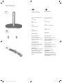
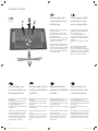
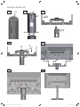
Inhoud van de le-
vering
Montage-instructies
(niet afgebeeld)
Afb. 1
Floor Stand 8
Afb. 2
Twee centreerstiften
Afb. 3
Textielslang
Technische gegevens
Floor Stand 8 32-40
Afmetingen (cm)
50,0 x 45,0 x 50,0 (B x H x D),
Diameter standvoet ca. 50,0 cm
Gewicht (kg) ca. 9,8
Floor Stand 8 42-47
Afmetingen (cm)
56,0 x 45,0 x 56,0 (B x H x D),
Diameter standvoet ca. 56,0 cm
Gewicht (kg) ca. 11,8
Tips voor het uitpakken
Gebruik voor het verwijderen van
de beschermfolie en plakband
geen scherpe voorwerpen, zoals
messen. Daardoor zou de Floor
Stand 8 beschadigd kunnen
worden.
Scope of delivery
Installation instructions
(not illustrated)
Fig. 1
Floor Stand 8
Fig. 2
Two centring pins
Fig. 3
Fabric hose
Technical Data
Floor Stand 8 32-40
Dimensions (cm)
50.0 x 45.0 x 50.0 (W x H x D),
Diameter stand foot approx.
50.0 cm
Weight (kg) approx. 9.8
Floor Stand 8 42-47
Dimensions (cm)
56.0 x 45.0 x 56.0 (W x H x D),
Diameter stand foot approx.
56.0 cm
Weight (kg) approx. 11.8
Unpacking instruction
Do not use any sharp objects,
such as a knife, to remove the
protective foil and adhesive ta-
pes. The Floor Stand 8 could be
damaged here.
Contenu de la li-
vraison
Notice de montage
(non représentée)
Ill. 1
Floor Stand 8
Ill. 2
Deux ergots de centrage
Ill. 3
Gaine fl exible en tissu
Caractéristiques techniques
Floor Stand 8 32-40
Dimensions (cm)
50,0 x 45,0 x 50,0 (l x h x p)
Diamètre du pied: 50,0 cm
environ
Poids (kg) env. 9,8
Floor Stand 8 42-47
Dimensions (cm)
56,0 x 45,0 x 56,0 cm (l x h x p)
Diamètre du pied: 56,0 cm
environ
Poids (kg) env. 11,8
Instruction de déballage
N’utilisez pas d’objets coupants,
comme un couteau, pour enlever
le plastique de protection et
le ruban adhésif. Cela pourrait
endommager le Floor Stand 8.
Volumen de sumi-
nistro
Instrucciones de montaje
(no aparecen en la ilustración)
Fig. 1
Floor Stand 8
Fig. 2
Dos pasadores de centrado
Fig. 3
Tubo de tela
Datos técnicos
Floor Stand 8 32-42
Dimensiones (cm)
50,0 x 45,0 x 50,0 (ancho x
altura x profundidad),
diámetro del pie de apoyo aprox.
50,0 cm
Peso (kg) aprox. 9,8
Floor Stand 8 42-47
Dimensiones (cm)
56,0 x 45,0 x 56,0 (ancho x
altura x profundidad),
diámetro del pie de apoyo aprox.
50,0 cm
Peso (kg) aprox. 11,8
Nota para el desembalaje
No utilice ningún utensilio
afi lado como, por ejemplo, un
cuchillo, para retirar las láminas
protectoras y las cintas adhesi-
vas, porque podría dañarse el
Floor Stand 8.
Floor Stand 8
34846_002_Floor Stand_8_08_02_2011_printer.indd 934846_002_Floor Stand_8_08_02_2011_printer.indd 9 08.02.2011 14:25:3708.02.2011 14:25:37

10
Floor Stand 8
TV - Gerät Adapter Art. Nr.
Spheros R 32/37 Adapter Floor Stand 5 67486B00
Xelos A 32/37
Modus L 32/37
Connect 32 Adapter Floor Stand C 32 70238B00
Connect 37/42 Adapter Floor Stand C 37/42 70107B00
Art 32/37/42/47 SL Adapter Floor Stand A 32-47 70465T00
Xelos 32/37/42 SL
Individual 32 LED Adapter Floor Stand 8 I 32 50498B00
Individual 40/46 LED Adapter Floor Stand 8 I 40/46 50499B00
Connect 32/40 LED Adapter Floor Stand 8 C/A 32-46 71042T00
Art 32/37/40/46 LED
Xelos 32/40 LED
Zuordnung der Adapter auf TV-Geräte
Zur Montage des TV-Gerätes am Floor Stand 8 wird ein Adapter be-
nötigt. Je nach TV-Gerät wird ein unterschiedlicher Adapter verwen-
det. Eine Übersicht aller verfügbaren Adapter und deren Zuordnung
auf TV-Geräte fi nden Sie in der unten dargestellten Tabelle.
Applicazione degli adattatori sugli appa-
recchi TV
Per montare l’apparecchio TV sul Floor Stand 8 serve un adattatore.
Ogni apparecchio TV richiede un adattatore diverso. Una panoramica
degli adattatori disponibili e la rispettiva assegnazione agli apparecchi
TV è riportata nella tabella riportata in basso.
Apparecchio TV Adattatore Cod. art.
Spheros R 32/37 Adapter Floor Stand 5 67486B00
Xelos A 32/37
Modus L 32/37
Connect 32 Adapter Floor Stand C 32 70238B00
Connect 37/42 Adapter Floor Stand C 37/42 70107B00
Art 32/37/42/47 SL Adapter Floor Stand A 32-47 70465T00
Xelos 32/37/42 SL
Individual 32 LED Adapter Floor Stand 8 I 32 50498B00
Individual 40/46 LED Adapter Floor Stand 8 I 40/46 50499B00
Connect 32/40 LED Adapter Floor Stand 8 C/A 32-46 71042T00
Art 32/37/40/46 LED
Xelos 32/40 LED
Toewijzing van de adapters aan tv-toe-
stellen
het monteren van het tv-toestel op de Floor Stand 8 hebt u een ad-
apter nodig. Voor ieder tv-toestel wordt een andere adapter gebruikt.
Een overzicht van alle beschikbare adapters en hun toewijzing aan
tv-toestellen vindt u in de tabel hieronder.
Tv-toestel Adapter Artikelnr.
Spheros R 32/37 Adapter Floor Stand 5 67486B00
Xelos A 32/37
Modus L 32/37
Connect 32 Adapter Floor Stand C 32 70238B00
Connect 37/42 Adapter Floor Stand C 37/42 70107B00
Art 32/37/42/47 SL Adapter Floor Stand A 32-47 70465T00
Xelos 32/37/42 SL
Individual 32 LED Adapter Floor Stand 8 I 32 50498B00
Individual 40/46 LED Adapter Floor Stand 8 I 40/46 50499B00
Connect 32/40 LED Adapter Floor Stand 8 C/A 32-46 71042T00
Art 32/37/40/46 LED
Xelos 32/40 LED
TV set Adapter Art. No.
Spheros R 32/37 Adapter Floor Stand 5 67486B00
Xelos A 32/37
Modus L 32/37
Connect 32 Adapter Floor Stand C 32 70238B00
Connect 37/42 Adapter Floor Stand C 37/42 70107B00
Art 32/37/42/47 SL Adapter Floor Stand A 32-47 70465T00
Xelos 32/37/42 SL
Individual 32 LED Adapter Floor Stand 8 I 32 50498B00
Individual 40/46 LED Adapter Floor Stand 8 I 40/46 50499B00
Connect 32/40 LED Adapter Floor Stand 8 C/A 32-46 71042T00
Art 32/37/40/46 LED
Xelos 32/40 LED
Assigning the adapter to TV sets
An adapter is required to install the TV set onto Floor Stand 8. The
adapter required varies depending upon which TV set is used. An
overview of all available adapters and how to assign them to TV sets
can be found in the table below.
34846_002_Floor Stand_8_08_02_2011_printer.indd 1034846_002_Floor Stand_8_08_02_2011_printer.indd 10 08.02.2011 14:25:3708.02.2011 14:25:37

11
Floor Stand 8
Recherche de l’adaptateur correspon-
dant au téléviseur
Vous avez besoin d’un adaptateur lorsque vous voulez monter le
téléviseur sur un Floor Stand 8. Le type d’adaptateur dépend du type
de téléviseur à installer. Vous trouverez un récapitulatif de tous les
adaptateurs disponibles et leur correspondance avec les téléviseurs
dans le tableau ci-dessous.
Asignación del adaptador a los televi-
sores
Para montar el televisor en el Floor Stand 8 se necesita un adaptador.
Dependiendo del televisor se utilizará un adaptador diferente. En la
siguiente tabla hallará un resumen de todos los adaptadores disponi-
bles y su asignación a los diferentes televisores.
Téléviseurs Adaptateurs N° d´article
Spheros R 32/37 Adapter Floor Stand 5 67486B00
Xelos A 32/37
Modus L 32/37
Connect 32 Adapter Floor Stand C 32 70238B00
Connect 37/42 Adapter Floor Stand C 37/42 70107B00
Art 32/37/42/47 SL Adapter Floor Stand A 32-47 70465T00
Xelos 32/37/42 SL
Individual 32 LED Adapter Floor Stand 8 I 32 50498B00
Individual 40/46 LED Adapter Floor Stand 8 I 40/46 50499B00
Connect 32/40 LED Adapter Floor Stand 8 C/A 32-46 71042T00
Art 32/37/40/46 LED
Xelos 32/40 LED
Televisor Adaptador Nº de ref.
Spheros R 32/37 Adapter Floor Stand 5 67486B00
Xelos A 32/37
Modus L 32/37
Connect 32 Adapter Floor Stand C 32 70238B00
Connect 37/42 Adapter Floor Stand C 37/42 70107B00
Art 32/37/42/47 SL Adapter Floor Stand A 32-47 70465T00
Xelos 32/37/42 SL
Individual 32 LED Adapter Floor Stand 8 I 32 50498B00
Individual 40/46 LED Adapter Floor Stand 8 I 40/46 50499B00
Connect 32/40 LED Adapter Floor Stand 8 C/A 32-46 71042T00
Art 32/37/40/46 LED
Xelos 32/40 LED
34846_002_Floor Stand_8_08_02_2011_printer.indd 1134846_002_Floor Stand_8_08_02_2011_printer.indd 11 08.02.2011 14:25:3708.02.2011 14:25:37
Page is loading ...

13
Floor Stand 8
Cablaggio del FLOOR
STAND 8
Appoggiare il FLOOR STAND 8 lateralmente
su una superfi cie morbida (tessuto-non-
tessuto o coperta). In questo modo si preven-
gono eventuali danneggiamenti del piede del
Floor Stand 8.
Prendere un cavo e farlo passare attraverso
l’apertura nel piede passando attraverso
il tubo del FLOOR STAND 8. Farlo scor-
rere in avanti fi no a vedere il connettore
all’estremità del tubo (fi g. 4).
Estrarre il cavo tirandolo dall‘apertura.
Procedere allo stesso modo anche per tutti
gli altri cavi.
Avvertenza. Far passare per primi i cavi con il
connettore più grande (ad es. il cavo Scart).
Accertarsi di non posare i cavi all’interno del
FLOOR STAND 8 con eccessiva tensione. Una
tensione eccessiva dei cavi posati può osta-
colare il movimento rotatorio dello schermo.
Prestare attenzione alle ulteriori operazioni di
cablaggio illustrate nella fi gura 5.
Il piede del FLOOR STAND 8 dispone di un
serracavo girevole (K). Esso facilita il fi ssaggio
dei cavi sotto il piatto. Far passare i cavi sotto
il serracavo facendoli scorrere all’indietro
come illustrato nella fi gura 5. Avvertenza:
Posare i cavi uno accanto all’altro.
Al termine, appoggiare il Floor Stand 8 sul
pavimento. Far passare i cavi uno di seguito
all’altro attraverso un tubo di tessuto (fi g. 6,
freccia G).
Avvertenza. Far passare per primi i cavi con il
connettore più grande (ad es. il cavo Scart).
Il diametro del tubo cavi aumenta se, rac-
cogliendone le estremità, lo si tira nel senso
della larghezza.
Questa operazione agevola il passaggio dei
cavi completi di connettori.
E‘ prevista anche la possibilità di posare i cavi
collegati al Floor Stand in un tubo di tessu-
to (fi g. 6, freccia H). Questo accorgimento
consente di ottenere un effetto di maggiore
eleganza. La dotazione del Floor Stand 8 non
comprende un secondo tubo di tessuto. Il
tubo può essere acquistato della lunghezza
desiderata presso il proprio rivenditore di
fi ducia oppure presso il nostro servizio clienti:
Tubo cavi nero:
Codice articolo: 31947 004
Tubo cavi argento:
Codice articolo: 31947 005
Nota per il cablaggio dell‘Individual 32/40/46
LED:
far passare il tubo di tessuto (G) attraverso
le due aperture dell‘adattatore (vedi pag.
28/32, fi g. 23/30, C1).
FLOOR STAND 8 bekabe-
len
Leg de FLOOR STAND 8 zijdelings op een
zachte ondergrond (bijv. vlies, deken). Op die
manier voorkomt u schade aan de voet van
de Floor Stand 8.
Neem een kabel en leid die via de opening
in de voet in de buis van de FLOOR STAND 8
naar binnen. Duw hem erdoor tot de stekker
aan het buisuiteinde verschijnt (afb. 4).
Trek de kabel uit de opening naar buiten.
Doe hetzelfde met al de andere kabels.
Opmerking. Leid de kabels met de grootste
stekkers (bijv. Scart-kabel) eerst door de buis.
Zorg ervoor dat de kabels in de FLOOR
STAND 8 niet te strak worden geleid. Een te
strakke kabelgeleiding kan de draaibeweging
van het beeldscherm belemmeren.
Kijk naar afb. 5 voor de verdere bekabeling.
De voet van de FLOOR STAND 8 beschikt over
een draaibare kabelhouder (K). De vergem-
akkelijkt het bevestigen van de kabel onder
de voet. Leid de kabel onder de kabelhouder
zoals getoond in afb. 5 naar achter door.
Opmerking: Leg de kabels naast elkaar.
Zet de Floor Stand 8 vervolgens op de grond.
Trek de kabels een voor een door de textiels-
lang (afb. 6, pijl G).
Opmerking. Leid de kabels met de grootste
stekkers (bijv. Scart-kabel) eerst door de buis.
U kunt de diameter van de kabelslang vergro-
ten door ze in de lengte samen te drukken.
Op die manier kunt u er de kabels met stek-
kers gemakkelijker doorvoeren.
U hebt ook de mogelijkheid de kabels naar
de Floor Stand door een textielslang (afb. 6,
pijl H) te leiden. Dat oogt eleganter. Er wordt
echter geen tweede textielslang bij de Floor
Stand 8 geleverd. Die kunt u in de gewenste
lengte kopen bij uw dealer of bij onze klan-
tendienst:
Kabelslang zwart:
Artikelnummer: 31947 004
Kabelslang zilver:
Artikelnummer: 31947 005
Opmerking in verband met de bekabeling
van de Individual 32/40/46 LED:
leid de textielslang (G) door de beide openin-
gen van de adapter (zie pagina 28/32, afb.
23/30, C1).
.
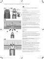
FLOOR STAND 8 cabling
Place the FLOOR STAND 8 on a soft surface
on the side (e.g. fl eece, blanket). This pre-
vents damage to the foot of the Floor Stand
8.
Take a cable and feed it through the opening
in the foot into the tube of the FLOOR STAND
8. Push it forwards until the plug appears at
the end of the tube (Fig. 4).
Pull the cable out of the opening.
Repeat the procedure for all other cables.
Note. First guide the cable with the biggest
plug (e.g. Scart cable) through.
Make sure that the cables are not laid too
tightly in the FLOOR STAND 8. Cables which
are too tight can hinder the rotational move-
ment of the screen.
See Figure 5 for the further cabling.
The base of the FLOOR STAND 8 has a tur-
ning cable clip (K). This enables the cables to
be fi tted more easily under the plate. Guide
the cables under the cable clip to the rear as
shown in fi gure 5. Note: Lay the cables next
to each other.
Then place the Floor Stand 8 on the fl oor.
Pull the cables one after another through the
fabric hose (Fig. 6, arrow G).
Note. First guide the cable with the biggest
plug (e.g. Scart cable) through.
The diameter of the cable hose increases
when you push the ends together.
This makes it easier to push through the
cables with plugs.
You also have the option of routing the
cables to the Floor Stand in a fabric hose
(Figure 6, arrow H). This looks more elegant.
A second fabric hose is not included in the
scope of supply of the Floor Stand 8. This
is available in the desired length from your
dealer or from our after sales service.
Cable hose, black:
Part number: 31947 004
Cable hose, silver:
Part number: 31947 005
Note for the cabling of the Individual
32/40/46 LED:
Guide the fabric hose (G) through the two
openings on the adapter (see page 28/32,
Figure 23/30, C1).
.
34846_002_Floor Stand_8_08_02_2011_printer.indd 1334846_002_Floor Stand_8_08_02_2011_printer.indd 13 08.02.2011 14:25:3808.02.2011 14:25:38
Page is loading ...

15
34846_002_Floor Stand_8_08_02_2011_printer.indd 1534846_002_Floor Stand_8_08_02_2011_printer.indd 15 08.02.2011 14:25:3808.02.2011 14:25:38
Page is loading ...

17
Demontage van
het aanwezige op-
stellingssysteem
Alvorens het beeldscherm op
de FLOOR STAND 8 kan worden
gemonteerd, moet het aanwe-
zige opstellingssysteem worden
gedemonteerd.
Zet het tv-toestel in het kantelbe-
reik loodrecht.
Kijk naar fi guur 4 voor de verde-
re demontage.
Een tweede persoon moet het
tv-toestel vasthouden.
Verwijder de beide schroeven
(pijl e1, e2) met de hoekschroe-
vendraaier (D).
Neem het tv-toestel af (afb. 5)
en leg het, indien nodig, met
de schermzijde op een zachte
ondergrond (vlies of deken).
Disassembly of the
existing installation
solution
Before the screen can be moun-
ted on the FLOOR STAND 8, the
existing installation solution must
be removed.
Set the TV set vertically in the tilt
range.
See fi gure 4 for further disas-
sembly.
Get a second person to hold the
TV set.
Remove the two screws (arrow
e1, e2) using the angled wrench
(D).
Remove the TV set (Figure 5)
and place it, if necessary, screen
down on a soft base (felt or
blanket).
Démontage de la
solution d’installation
actuelle
Avant d‘installer l‘écran sur le
FLOOR STAND 8, la solution
d’installation existante doit être
démontée.
Réglez l‘inclinaison du téléviseur
sur vertical.
Observez l‘illustration 4 pour la
poursuite du démontage.
Une deuxième personne doit
tenir le téléviseur.
Retirez les deux vis (fl èches e1,
e2) à l‘aide du tournevis d’angle
(D).
Enlevez le téléviseur (ill. 5) et
déposez-le, si nécessaire en
faisant reposer l’écran sur un
support souple (non-tissé ou
couverture).
Desmontaje del
elemento de colo-
cación existente
Antes de que pueda montarse la
pantalla en el FLOOR STAND 8,
deberá desmontarse el elemento
de colocación existente.
Coloque el televisor en posición
vertical en el área de inclinación.
Para continuar con el desmonta-
je, observe la ilustración 4.
Una segunda persona debe
sujetar el televisor.
Retire los dos tornillos (fl echas
e1, e2) con la llave angular (D).
Retire el televisor (fi g. 5) y, en
caso necesario, colóquelo sobre
una base suave (fi eltro o manta)
con el lado de la pantalla hacia
abajo.
Spheros R / Xelos A / Modus L
34846_002_Floor Stand_8_08_02_2011_printer.indd 1734846_002_Floor Stand_8_08_02_2011_printer.indd 17 08.02.2011 14:25:3808.02.2011 14:25:38
Page is loading ...

19
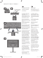
Montage Spheros R / Xelos A / Modus L
Tv-toestel op de
FLOOR STAND 8
monteren
De montage gebeurt met behulp
van een adapter (Adapter Floor
Stand 5, afb. 7, C).
Brengt eerst de beide centreer-
stiften (pijl a1, a2) aan in de
overeenkomstige boringen in de
FLOOR STAND 8 (afb. 6).
Neem de adapter (C). Monteer
hem zoals getoond in afb. 7 op
de FLOOR STAND 8.
Zorg ervoor dat de centreer-
pennen in de boringen van de
adapter dringen.
Draai de beide schroeven (pijl b1,
b2) met de hoekschroevensleutel
(D) in en span ze aan met een
aanhaalmoment van ca. 5 Nm.
Plaats het tv-toestel op de FLOOR
STAND 8 (afb. 8).
LET OP! Het tv-toestel moet door
twee personen op de FLOOR
STAND 8 worden getild. Verge-
wis u ervan dat de achterzijde
van het tv-toestel en de kabelo-
peningen in de FLOOR STAND 8
zich langs dezelfde kant bevin-
den.
Let er bij het neerlaten van het
tv-toestel op dat de standaard-
houder over de adapter van de
FLOOR STAND 8 schuift.
Op de voorkant van de adapter
bevindt zich een spanstift.
De spanstift voorkomt dat het
tv-toestel verkeerd gemonteerd
wordt.
Het tv-toestel is correct gepositi-
oneerd wanneer de boringen van
de standaardhouder en van de
adapter tegenover elkaar liggen.
Voor de bevestiging gebruikt u
de eerder uit de tafelvoet ver-
wijderde schroeven (pijl e1, e2).
Draai de schroeven in en span ze
aan met de hoekschroevensleu-
tel. Aanhaalmoment (afb. 8) ca.
5 Nm.
Sluit de verbindingskabels aan en
breng de aansluitingsafdekking
weer aan op het tv-toestel (afb.
9).
Mounting the TV
set on the FLOOR
STAND 8
An adapter (Adapter Floor Stand
5, Figure 7, C) is used for the
installation.
First place the two centring pins
(arrow a1, a2) in the correspon-
ding holes on the FLOOR STAND
8 (Figure 8).
Take the adapter (C). Mount
this on the FLOOR STAND 8, as
shown in Figure 7.
Make sure that the centring pins
enter the holes in the adapter.
Turn both screws (arrow b1, b2)
in with the angled wrench (D)
and tighten them with a torque
of approx. 5 Nm.
Place the TV set on the FLOOR
STAND 8 (Figure 8).
ATTENTION! Two persons should
lift the TV set onto the FLOOR
STAND 8. Make sure that the
back of the TV set and the cable
openings in the FLOOR STAND 8
are on the same side.
Make sure that the standard hol-
der grips over the adapter of the
FLOOR STAND 8 when lowering
the TV set.
There is a clamping pin at the
front of the adapter.
The clamping pin prevents the
TV set from being installed
incorrectly.
The TV set is correctly positioned
if the holes of the
standard holder and the adapter
correspond.
Use the screws previously remo-
ved from the table foot (arrow
e1, e2) for fastening. Turn in the
screw and tighten it with the
angled wrench. Torque (Figure 8)
approx. 5 Nm.
Connect the connecting cables
and place the connection cover
on the TV set again (Figure 9).
Monter le télévi-
seur sur le FLOOR
STAND 8
Le montage s‘effectue à l‘aide
d‘un adaptateur (adaptateur
Floor Stand 5, ill. 7, C).
Placez tout d‘abord les deux er-
gots de centrage (fl èches a1, a2)
dans les orifi ces correspondants
du FLOOR STAND 8 (ill. 8).
Prenez l‘adaptateur (C). Montez
celui-ci sur le FLOOR STAND 8,
comme indiqué dans l´ill. 7.
Veillez à ce que les ergots de
centrage pénètrent dans les trous
de l’adaptateur.
Vissez les deux vis (fl èches b1,
b2) avec le tournevis d’angle
(D) et serrez avec un couple de
serrage de 5 Nm environ.
Placez le téléviseur sur le FLOOR
STAND 8 (ill. 8).
ATTENTION ! Il faut deux perso-
nnes pour tenir le téléviseur sur
le FLOOR STAND 8. Veillez à ce
que l’arrière du téléviseur et les
ouvertures pour les câbles du
FLOOR STAND 8 se trouvent du
même côté.
Veillez à ce que le support stan-
dard ait pris avec l‘adaptateur
du FLOOR STAND 8 lorsque vous
abaissez le téléviseur.
Le côté avant de l‘adaptateur
comporte une goupille de ser-
rage.
La goupille de serrage évite que
le téléviseur ne soit mal monté.
Le téléviseur est correctement
positionné lorsque les orifi ces
du support standard et de
l’adaptateur coïncident.
Pour la fi xation, utilisez les vis
que vous avez ôtées auparavant
du pied de table (fl èches e1, e2).
Vissez les vis et serrez-les avec
le tournevis d’angle. Couple de
serrage (ill.8) de 5 Nm environ.
Raccordez les câbles de raccor-
dement et remettez le couvercle
de raccordement sur le téléviseur
(ill.9).
Montaje del tele-
visor en el FLOOR
STAND 8
El montaje tiene lugar utilizando
un adaptador (adaptador para
Floor Stand 5, fi g. 7, C).
Inserte en primer lugar los dos
pasadores de centrado (fl echas
a1, a2) en los correspondientes
orifi cios del FLOOR STAND 8 (fi g.
8).
Coja el adaptador (C). Móntelo
en el FLOOR STAND 8 como se
indica en la fi gura 7.
Asegúrese de que los pasadores
de centrado quedan introducidos
en los orifi cios del adaptador.
Enrosque los dos tornillos
(fl echas b1, b2) con la llave an-
gular (D) y apriételos con un par
de 5 Nm aprox.
Coloque el televisor sobre el
FLOOR STAND 8 (fi g. 8).
¡ATENCIÓN! El televisor debe ser
colocado sobre el FLOOR STAND
8 por dos personas. Asegúrese
de que la parte posterior del te-
levisor y las aberturas para cables
del FLOOR STAND 8 queden del
mismo lado.
Asegúrese de que, al depositar el
televisor, el soporte estándar en-
caje en el adaptador del FLOOR
STAND 8.
En la parte delantera del adapta-
dor se encuentra un pasador de
fi jación.
El pasador de fi jación evita que
el televisor pueda montarse de
manera incorrecta.
El televisor estará correctamente
colocado si los orifi cios del so-
porte estándar coinciden con los
del adaptador.
Para fi jarlo, utilice los tornillos
que antes retiró del pie de mesa
(fl echas e1, e2). Enrosque los
tornillos y apriételos con la llave
angular. Par de 5 Nm aprox. (fi g.
8).
Conecte los cables de conexión
y coloque de nuevo la tapa de
conexiones en el televisor (fi g. 9).
34846_002_Floor Stand_8_08_02_2011_printer.indd 1934846_002_Floor Stand_8_08_02_2011_printer.indd 19 08.02.2011 14:25:3908.02.2011 14:25:39

20
Connect 32-42
Demontage der
vorhandenen Auf-
stelllösung
Beachten Sie für die weitere De-
montage, Abb. 10.
Eine zweite Person muss das
TV-Gerät halten damit es nicht
beschädigt wird.
Entfernen Sie die drei Schrauben
mit einem Schraubenschlüssen
T20 (Abb. 10, Pfeile C).
Ziehen Sie den Fuß heraus oder
nehmen Sie das TV-Gerät nach
oben ab. Legen Sie das TV-Gerät,
wenn nötig mit der Bildschirm-
seite auf eine weiche Unterlage
(Vlies oder Decke).
c
c
c
10
Smontaggio della
soluzione di sup-
porto disponibile
Prestare attenzione alle ulteriori
operazioni di smontaggio illus-
trate nella fi gura 10.
Una seconda persona deve
sorreggere l’apparecchio TV in
modo che non possa essere dan-
neggiato.
Estrarre le tre viti (fi g. 10, frecce
C).
Estrarre il piede oppure solle-
vare l‘apparecchio TV verso
l‘alto. Se necessario, appoggiare
l‘apparecchio TV con il lato dello
schermo su una base soffi ce (tes-
suto-non-tessuto o coperta).
Demontage van
het aanwezige op-
stellingssysteem
Kijk naar afb. 10 voor de verdere
demontage.
Een tweede persoon moet het
tv-toestel vasthouden zodat het
niet beschadigd wordt.
Verwijder de drie schroeven (afb.
10, pijl C).
Trek de voet uit het tv-toestel of
til het tv-toestel op om het van
de voet af te nemen. Leg het
tv-toestel indien nodig met de
schermzijde op een zachte on-
dergrond (vlies of deken).
Disassembly of the
existing installation
solution
See Figure 10 for the further di-
sassembly.
A second person must hold the
TV set to prevent it from being
damaged.
Remove the three screws (Figure
10, arrows C).
Pull out the base or lift off the
TV set
upwards. Place the TV set down
with the screen on a soft under-
lay (fl eece or blanket) if neces-
sary.
Démontage de la
solution d’installation
actuelle
Observez l‘illustration 10 pour la
poursuite du démontage.
Une deuxième personne doit te-
nir le téléviseur pour qu’il ne soit
pas endommagé.
Retirez les trois vis (ill. 10, fl èches
C).
Enlevez le pied ou retirez le télé-
viseur vers le haut.
Placez le téléviseur si nécessaire
avec le côté de l’écran sur un
support souple (non-tissé ou
couverture).
Desmontaje del
elemento de colo-
cación existente
Para continuar con el desmonta-
je, observe la fi gura 10.
Una segunda persona deberá su-
jetar el televisor para que éste no
sufra daños.
Retire los tres tornillos (fi g. 10,
fl echas C).
Extraiga el pie o retire el televisor
levantándolo. En caso necesario,
coloque el televisor de tal forma
que la pantalla se apoye sobre
una base suave (fi eltro o manta).
34846_002_Floor Stand_8_08_02_2011_printer.indd 2034846_002_Floor Stand_8_08_02_2011_printer.indd 20 08.02.2011 14:25:3908.02.2011 14:25:39

21
34846_002_Floor Stand_8_08_02_2011_printer.indd 2134846_002_Floor Stand_8_08_02_2011_printer.indd 21 08.02.2011 14:25:4008.02.2011 14:25:40
Page is loading ...

23
Connect 32-42
Tv-toestel op de
FLOOR STAND 8
monteren
De montage gebeurt met behulp
van een adapter (Adapter Floor
Stand C32 / Adapter Floor Stand
C37/C42, afb. 12, C).
Brengt eerst de beide centreer-
stiften (pijl a1, a2) aan in de
overeenkomstige boringen in de
FLOOR STAND 8 (afb. 11).
Neem de adapter (C). Monteer
hem zoals getoond in afb. 12 op
de FLOOR STAND 8.
Zorg ervoor dat de centreer-
pennen in de boringen van de
adapter dringen.
Draai de beide schroeven (pijl b1,
b2) met de hoekschroevensleutel
(D) in en span ze aan met een
aanhaalmoment van ca. 5 Nm.
Plaats het tv-toestel op de FLOOR
STAND 8 (afb. 13).
LET OP! Het tv-toestel moet door
twee personen op de FLOOR
STAND 8 worden getild. Verge-
wis u ervan dat de achterzijde
van het tv-toestel en de kabelo-
peningen in de FLOOR STAND 8
zich langs dezelfde kant bevin-
den.
Voor het bevestigen (afb. 14)
gebruikt u de eerder uit de Table
Stand verwijderde schroeven.
Draai de schroeven in en span ze
aan met de hoekschroevensleutel
(afb. 14). Aanhaalmoment ca.
2 Nm.
Sluit de verbindingskabels aan en
breng de aansluitingsafdekking
weer aan op het tv-toestel.
Mounting the TV
set on the FLOOR
STAND 8
An adapter (Adapter Floor Stand
C32 / Adapter Floor Stand C37/
C42, Figure 12, C) is used for the
installation.
First place the two centring pins
(arrow a1, a2) in the correspon-
ding holes on the FLOOR STAND
8 (Figure 11).
Take the adapter (C). Mount
this on the FLOOR STAND 8, as
shown in Figure 12.
Make sure that the centring pins
enter the holes in the adapter.
Turn both screws (arrow b1, b2)
in with the angled wrench (D)
and tighten them with a torque
of approx. 5 Nm.
Place the TV set on the FLOOR
STAND 8 (Figure 13).
ATTENTION! Two persons should
lift the TV set onto the FLOOR
STAND 8. Make sure that the
back of the TV set and the cable
openings in the FLOOR STAND 8
are on the same side.
Use the screws you removed pre-
viously from the table stand for
fastening (Figure 14). Turn in the
screws and tighten them with
the wrench (Figure 14), torque
approx. 2 Nm.
Connect the connecting cables
and place the connection cover
on the TV set again.
Montage de
l’écran sur le
FLOOR STAND 8
Le montage s‘effectue à l‘aide
d‘un adaptateur (adaptateur
Floor Stand C32 / adaptateur
C37/C42, ill. 12, C).
Placez tout d‘abord les deux er-
gots de centrage (fl èches a1, a2)
dans les orifi ces correspondants
du FLOOR STAND 8 (ill. 11).
Prenez l‘adaptateur (C). Montez
celui-ci sur le FLOOR STAND 8,
comme indiqué dans l´ill. 12.
Veillez à ce que les ergots de
centrage pénètrent dans les trous
de l’adaptateur.
Vissez les deux vis (fl èches b1,
b2) avec le tournevis d’angle
(D) et serrez avec un couple de
serrage de 5 Nm environ.
Placez le téléviseur sur le FLOOR
STAND 8 (ill. 13).
ATTENTION ! Il faut deux perso-
nnes pour tenir le téléviseur sur
le FLOOR STAND 8. Veillez à ce
que l’arrière du téléviseur et les
ouvertures pour les câbles du
FLOOR STAND 8 se trouvent du
même côté.
Pour le fi xer (ill. 14), utilisez les
vis que vous avez ôtées aupara-
vant du Table Stand. Vissez les vis
et serrez-les avec la clé (ill. 14),
couple de serrage d‘env. 2 Nm.
Raccordez les câbles de raccorde-
ment et remettez le couvercle de
raccordement sur le téléviseur .
Montaje del tele-
visor en el FLOOR
STAND 8
El montaje tiene lugar utilizando
un adaptador (adaptador para
Floor Stand C32 / adaptador para
Floor Stand C37/C42, fi g. 12, C).
Inserte en primer lugar los dos
pasadores de centrado (fl echas
a1, a2) en los correspondientes
orifi cios del FLOOR STAND 8 (fi g.
11).
Coja el adaptador (C). Móntelo
en el FLOOR STAND 8 como se
indica en la fi gura 12.
Asegúrese de que los pasadores
de centrado quedan introducidos
en los orifi cios del adaptador.
Enrosque los dos tornillos
(fl echas b1, b2) con la llave an-
gular (D) y apriételos con un par
de 5 Nm aprox.
Coloque el televisor sobre el
FLOOR STAND 8 (fi g. 13).
¡ATENCIÓN! El televisor debe ser
colocado sobre el FLOOR STAND
8 por dos personas. Asegúrese
de que la parte posterior del te-
levisor y las aberturas para cables
del FLOOR STAND 8 queden del
mismo lado.
Para fi jarlo (fi g. 14), utilice los
tornillos que antes retiró del Ta-
ble Stand. Enrosque los tornillos
y apriételos con la llave de ajuste
(fi g. 14) con un par de 2 Nm
aprox.
Conecte los cables de conexión
y coloque de nuevo la tapa de
conexiones en el televisor
34846_002_Floor Stand_8_08_02_2011_printer.indd 2334846_002_Floor Stand_8_08_02_2011_printer.indd 23 08.02.2011 14:25:4108.02.2011 14:25:41
Page is loading ...

25
Art 32-47 SL / Xelos 32-42 SL
Demontage van
het aanwezige op-
stellingssysteem
Alvorens het beeldscherm op
de FLOOR STAND 8 kan worden
gemonteerd, moet het aanwe-
zige opstellingssysteem worden
gedemonteerd.
Kijk naar afbeelding 15 en af-
beelding 16 voor de verdere
demontage.
Verwijder eerst de achterwandaf-
dekking van uw tv-toestel.
Verwijder de drie schroeven (af-
beelding 15, pijlen f1, f2, f3) met
de schroevendraaier (T20).
Een tweede persoon moet het
tv-toestel vasthouden zodat het
niet beschadigd wordt.
Trek de voet uit het tv-toestel of
til het tv-toestel op om het van
de voet af te nemen. Leg het
tv-toestel indien nodig met de
schermzijde op een zachte on-
dergrond (vlies of deken).
Disassembly of the
existing installation
solution
Before the screen can be moun-
ted on the FLOOR STAND 8, the
existing installation solution must
be removed.
See Figure 15 and Figure 16 for
further disassembly.
First remove the rear panel cover
of the TV set.
Remove the three screws (Figure
15, arrows f1, f2, f3) with the
angled wrench (T20).
A second person must hold the
TV set to prevent it from being
damaged.
Pull out the base or lift off the TV
set. Place the TV set down with
the screen on a soft underlay
(fl eece or blanket) if necessary.
Démontage de la
solution d’installation
actuelle
Avant d‘installer l‘écran sur le
FLOOR STAND 8, la solution
d’installation existante doit être
démontée.
Observez les illustrations 15 et
16 pour la poursuite du démon-
tage.
Retirez tout d‘abord le couvercle
de paroi arrière du téléviseur.
Enlevez les trois vis (illustration
15, fl èches f1, f2, f3) avec la clé
(T20).
Une deuxième personne doit
tenir le téléviseur pour qu’il ne
soit pas endommagé.
Enlevez le pied ou retirez le
téléviseur vers le haut. Placez le
téléviseur si nécessaire avec le
côté de l’écran sur un support
souple (non-tissé ou couverture).
Desmontaje del
elemento de colo-
cación existente
Antes de que pueda montarse la
pantalla en el FLOOR STAND 8,
deberá desmontarse el elemento
de colocación existente.
Para continuar con el desmonta-
je, observe las fi guras 15 y 16.
Retire en primer lugar la tapa
trasera del televisor.
Retire los tres tornillos (fi g. 15,
fl echas f1, f2, f3) con la llave de
ajuste (T20).
Una segunda persona deberá
sujetar el televisor para que éste
no sufra daños.
Extraiga el pie o retire el televisor
levantándolo. En caso necesario,
coloque el televisor de tal forma
que la pantalla se apoye sobre
una base suave (fi eltro o manta).
34846_002_Floor Stand_8_08_02_2011_printer.indd 2534846_002_Floor Stand_8_08_02_2011_printer.indd 25 08.02.2011 14:25:4108.02.2011 14:25:41
Page is loading ...

27
Tv-toestel op de
FLOOR STAND 8
monteren
De montage gebeurt met behulp
van een adapter (Adapter Floor
Stand A 32-47, afb. 18, C).
Brengt eerst de beide centreer-
stiften (pijl a1, a2) aan in de
overeenkomstige boringen in de
FLOOR STAND 8 (afb. 17).
Neem de adapter (C). Monteer
hem zoals getoond in afb. 18 op
de FLOOR STAND 8.
Zorg ervoor dat de centreerpen-
nen in de boringen van de adap-
ter dringen.
Draai de beide schroeven (pijl b1,
b2) met de hoekschroevensleutel
(D) in en span ze aan met een
aanhaalmoment van ca. 5 Nm.
Verwijder de achterwandafdek-
king van uw tv-toestel.
Plaats het tv-toestel op de FLOOR
STAND 8 (afb. 19).
LET OP! Het tv-toestel moet door
twee personen op de FLOOR
STAND 8 worden getild. Verge-
wis u ervan dat de achterzijde
van het tv-toestel en de kabelo-
peningen in de FLOOR STAND 8
zich langs dezelfde kant bevin-
den.
Voor de bevestiging gebruikt u
de eerder uit de tafelvoet ver-
wijderde schroeven. Draai de
schroeven in (afb. 19, pijlen e1,
e2, e3) en span ze aan met de
schroevendraaier (afb.19, D).
Aanhaalmoment ca. 2 Nm (licht-
jes aandraaien).
Sluit de verbindingskabels aan en
breng de aansluitingsafdekking
weer aan op het tv-toestel (afb.
20).
Mounting the TV
set on the FLOOR
STAND 8
An adapter (Adapter Floor Stand
A 32-47, Figure 18, C) is used for
the installation.
First place the two centring pins
(arrow a1, a2) in the correspon-
ding holes on the FLOOR STAND
8 (Figure 17).
Take the adapter (C). Mount
this on the FLOOR STAND 8, as
shown in Figure 18.
Make sure that the centring pins
enter the holes in the adapter.
Turn both screws (arrow b1, b2)
in with the angled wrench (D)
and tighten them with a torque
of approx. 5 Nm.
Remove the rear panel cover of
the TV set.
Place the TV set on the FLOOR
STAND 8 (Figure 19).
ATTENTION! Two persons should
lift the TV set onto the FLOOR
STAND 8. Make sure that the
back of the TV set and the cable
openings in the FLOOR STAND 8
are on the same side.
Use the screws previously remo-
ved from the table foot
for fastening. Turn the screws
(Figure 19, arrows e1, e2, e3) in
and
tighten them with the wrench
(Figure 19, D).
Torque approx. 2 Nm (tighten
slightly).
Connect the connecting cables
and place the connection cover
on the TV set again.
Monter le télévi-
seur sur le FLOOR
STAND 8
Le montage s‘effectue à l‘aide
d‘un adaptateur (adaptateur
Floor Stand A 32-47, ill. 18, C).
Placez tout d‘abord les deux er-
gots de centrage (fl èches a1, a2)
dans les orifi ces correspondants
du FLOOR STAND 8 (ill. 17).
Prenez l‘adaptateur (C). Montez
celui-ci sur le FLOOR STAND 8,
comme indiqué dans l´ill. 18.
Veillez à ce que les ergots de
centrage pénètrent dans les trous
de l’adaptateur.
Vissez les deux vis (fl èches b1,
b2) avec le tournevis d’angle (D)
et serrez avec un couple de ser-
rage de 5 Nm environ.
Retirez le couvercle de paroi arri-
ère du téléviseur.
Placez le téléviseur sur le FLOOR
STAND 8 (ill. 19).
ATTENTION ! Il faut deux perso-
nnes pour tenir le téléviseur sur
le FLOOR STAND 8. Veillez à ce
que l’arrière du téléviseur et les
ouvertures pour les câbles du
FLOOR STAND 8 se trouvent du
même côté.
Pour la fi xation, utilisez les vis
que vous avez ôtées auparavant
du pied de table. Vissez les vis
(ill. 19, fl èches e1, e2, e3) et
serrez-les avec la clé (ill. 19, D).
Couple de serrage d‘env. 2 Nm
(serrage en forçant modéré-
ment).
Fixez à nouveau sur le téléviseur
le couvercle de paroi arrière que
vous avez retiré auparavant (ill.
20).
Montaje del tele-
visor en el FLOOR
STAND 8
El montaje tiene lugar utilizando
un adaptador (adaptador para
Floor Stand A 32-47, fi g. 18, C).
Inserte en primer lugar los dos
pasadores de centrado (fl echas
a1, a2) en los correspondientes
orifi cios del FLOOR STAND 8 (fi g.
17).
Coja el adaptador (C). Móntelo
en el FLOOR STAND 8 como se
indica en la fi gura 18.
Asegúrese de que los pasadores
de centrado quedan introducidos
en los orifi cios del adaptador.
Enrosque los dos tornillos
(fl echas b1, b2) con la llave an-
gular (D) y apriételos con un par
de 5 Nm aprox.
Retire la tapa trasera del televi-
sor.
Coloque el televisor sobre el
FLOOR STAND 8 (fi g. 19).
¡ATENCIÓN! El televisor debe ser
colocado sobre el FLOOR STAND
8 por dos personas. Asegúrese
de que la parte posterior del te-
levisor y las aberturas para cables
del FLOOR STAND 8 queden del
mismo lado.
Para fi jarlo, utilice los tornillos
que antes retiró del pie de mesa.
Enrosque los tornillos (fi g. 19,
fl echas e1, e2, e3) y apriételos
con la llave de ajuste (fi g. 19, D).
Par de 2 Nm aprox. (apretar lige-
ramente).
Fije de nuevo en el televisor la
tapa trasera que había retirado
(fi g. 20).
Art 32-47 SL / Xelos 32-42 SL
34846_002_Floor Stand_8_08_02_2011_printer.indd 2734846_002_Floor Stand_8_08_02_2011_printer.indd 27 08.02.2011 14:25:4108.02.2011 14:25:41

28
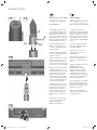
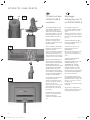
Individual 32 LED
a1
b1 b2
C1
D
C1
C2
e1
e2
D
N
N
R
R
f3
f4
f1
f2
21
22
23
24
25
26
27
34846_002_Floor Stand_8_08_02_2011_printer.indd 2834846_002_Floor Stand_8_08_02_2011_printer.indd 28 08.02.2011 14:25:4208.02.2011 14:25:42
Page is loading ...

30
Tv-toestel op de FLOOR STAND 8 mon-
teren
De montage gebeurt met behulp van een adapter (Adapter Floor
Stand 8 I 32, afb. 23, C1, C2).
Brengt eerst de centreerstift (pijl a1) aan in de overeenkomstige bo-
ring in de FLOOR STAND 8 (afb. 21).
Neem de adapter (C1). Monteer hem zoals getoond in afb. 21 op de
FLOOR STAND 8.
Zorg ervoor dat de centreerpen in de boring van de adapter dringt.
Draai de beide schroeven (pijl b1, b2) (M6x16) met de hoekschroe-
vensleutel (D) in en span ze aan met een aanhaalmoment van ca. 5
Nm.
Neem de adapter (C2). Monteer hem zoals getoond in afb. 23 op de
eerder gemonteerde adapter (C1).
Voorzie de beide voor de bevestiging benodigde schroeven (pijlen e1,
e2) (M6x20) van veerringen. Let op: de schroeven (e1, e2) moeten
eerst allebei een beetje worden ingedraaid. Vervolgens draait u ze
met de hoekschroevendraaier (D) handvast aan (afb. 24).
De adapter is nu helemaal op de FLOOR STAND 8 gemonteerd.
Verwijder de kabelaansluitafdekking van de achterkant van het tv-toe-
stel. Op de achterkant van het tv-toestel ziet u twee kleine openingen
(afb. 25, pijlen R).
De beide draagelementen van de FLOOR STAND 8 hebben bovenaan
een lipje (afb. 25, pijlen N). Uw tv-toestel weegt ca. 20 kg. Roep de
hulp in van een tweede persoon.
Hang het tv-toestel zo in de FLOOR STAND 8 dat de lipjes van de
draagelementen in de openingen in het tv-toestel zitten. Kijk daar-
voor naar afb. 25/26. Vergewis u ervan dat de bevestigingsnokjes
(FLOOR STAND 8) in de uitsparingen in de metalen plaat (tv-toestel)
zitten.
Gebruik voor de bevestiging de bijgeleverde schroeven (afb. 26, pijlen
f, M4x8).
Gebruik een snoerloze schroefmachine of een geschikte stabiele torx-
schroevendraaier T20 om de schroeven in te draaien.
Werkwijze, met schroefmachine:
In de verpakking van de adapter vindt u een schroefbit T20. Steek die
in uw schroefmachine. Stel de schroefmachine in op een zeer laag
toerental. Steek de schroef op de bit. Zet de schroef tegen een boring
aan (afb. 26, pijlen f) en draai ze in door er een beetje druk op uit te
oefenen. Zorg ervoor dat u de schroefmachine tijdig doet stoppen.
Anders kan de schroefverbinding beschadigd raken. Draai de schroef
lichtjes aan (2 Nm).
Ga voor de overige 3 schroeven op dezelfde manier te werk.
Het tv-toestel moet door een persoon worden vastgehouden tot het
aan de FLOOR STAND is vastgeschroefd. Anders bestaat het gevaar
dat het tv-toestel naar voren toe valt.
Sluit de verbindingskabels aan en breng de aansluitingsafdekking
weer aan op het tv-toestel.
Het tv-toestel is nu op de FLOOR STAND 8 gemonteerd (afb. 27.).
Mounting the TV set on the FLOOR
STAND 8
An adapter (Floor Stand 8 I 32 Adapter, Figure 23, C1, C2) is used for
the installation.
First place the centring pin (arrow a1) in the corresponding hole on
the FLOOR STAND 8 (Figure 21).
Take the adapter (C1). Mount this on the FLOOR STAND 8, as shown
in Figure 21.
Make sure that the centring pin enters the hole in the adapter.
Turn both screws (arrow b1, b2) (M6x16) in with the angled wrench
(D) and tighten them with a torque of approx. 5 Nm.
Take the adapter (C2). Mount this on the previously installed adapter
(C1), as shown in fi gure 23.
Take both of the screws required for mounting and put split washers
on them (arrow e1, e2) (M6x20). Be aware that both the screws (e1,
e2) have to be screwed in a little in the fi rst instance. Finish off by
screwing them in hand-tight using an Allen key (D) (fi g. 24).
The adapter is now completely mounted on the FLOOR STAND 8.
Remove the cable connection cover on the rear panel of your TV set.
You will see two small breakouts on the rear of the TV set (Figure 25,
arrows R).
Two lugs (Figure 25, arrows N) are located on the support member of
the FLOOR STAND 8. Your TV set weighs approx. 20 kg. Ask some-
one to help you hang in the TV set.
Hang the TV set in with the breakouts on the lugs of the FLOOR
STAND 8. See Figure 25/26 for this. Make sure that the lugs (FLOOR
STAND 8) have latched into the breakouts in the metal plate (TV set).
Use the screws provided for fastening (Figure 26, arrows f, M4x8).
We recommend a cordless screwdriver or a suitable sturdy Torx scre-
wdriver T20.
Procedure, with example cordless screwdriver:
The scope of supply of the adapter includes a screwdriver bit T20.
Place this in your cordless screwdriver. Set your cordless screwdriver
to a very low speed. Insert the screw onto the bit. Place the screw on
a drill hole (Figure 26, arrows f) and screw in with a little pressure.
Make sure you stop the screw from turning in suffi cient time. The
screwed joint could
otherwise be damaged. Tighten the screws slightly (2 Nm).
Repeat the procedure for the other 3 screws.
Someone must hold the TV set until it has been screwed to the Table
Stand. Otherwise there is a risk of the TV set falling forwards.
Connect the connecting cables and place the connection cover
on the TV set again.
The TV set is now mounted on the FLOOR STAND 8 (Figure 27).
Individual 32 LED
34846_002_Floor Stand_8_08_02_2011_printer.indd 3034846_002_Floor Stand_8_08_02_2011_printer.indd 30 08.02.2011 14:25:4208.02.2011 14:25:42
Page is loading ...

32
Individual 40/46 LED
a1
C1
D
b1 b2
C2
C1
e2
e1
D
G G
A
f3
f4
f1 f2
28 29 30
31
32
33
34
34846_002_Floor Stand_8_08_02_2011_printer.indd 3234846_002_Floor Stand_8_08_02_2011_printer.indd 32 08.02.2011 14:25:4208.02.2011 14:25:42
Page is loading ...
Page is loading ...
Page is loading ...
Page is loading ...
Page is loading ...
Page is loading ...
Page is loading ...
Page is loading ...
Page is loading ...
Page is loading ...
Page is loading ...
Page is loading ...
-
 1
1
-
 2
2
-
 3
3
-
 4
4
-
 5
5
-
 6
6
-
 7
7
-
 8
8
-
 9
9
-
 10
10
-
 11
11
-
 12
12
-
 13
13
-
 14
14
-
 15
15
-
 16
16
-
 17
17
-
 18
18
-
 19
19
-
 20
20
-
 21
21
-
 22
22
-
 23
23
-
 24
24
-
 25
25
-
 26
26
-
 27
27
-
 28
28
-
 29
29
-
 30
30
-
 31
31
-
 32
32
-
 33
33
-
 34
34
-
 35
35
-
 36
36
-
 37
37
-
 38
38
-
 39
39
-
 40
40
-
 41
41
-
 42
42
-
 43
43
-
 44
44


Ask a question and I''ll find the answer in the document
Finding information in a document is now easier with AI
in other languages
- italiano: LOEWE 69468B00 Scheda dati
- français: LOEWE 69468B00 Fiche technique
- español: LOEWE 69468B00 Ficha de datos
- Deutsch: LOEWE 69468B00 Datenblatt
- Nederlands: LOEWE 69468B00 Data papier
Related papers
-
LOEWE 32HD/DR+ User manual
-
LOEWE Spheros 20 SAT User manual
-
-
-
Beko BUDF 700 User manual
-
-
-
-
-
