6
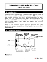
Deutsch Seriell RS-422/485 PCI Karte
4. Hardware Installation
Beachten Sie die folgenden Installationshinweise. Da es grosse Unterschiede bei Com-
putern gibt, können wir Ihnen nur eine generelle Anleitung zum Einbau der RS-422/485
PCI Karte geben. Bei Unklarheiten halten Sie sich bitte an die Betriebsanleitung Ihres
Computersystem.
•
Schalten Sie Ihren Rechner und alle angeschlossenen Peripheriegeräte aus und
ziehen Sie bei allen Geräten den Netzstecker.
•
Lösen Sie die Schrauben des Gehäuses auf der Rückseite Ihres Computers und
entfernen Sie vorsichtig das Gehäuse.
•
Suchen Sie einen freien PCI-Slot und stecken Sie die RS-422/485 PCI Karte vor-
sichtig in den ausgewählten PCI-Slot ein.
•
Beachten Sie das die RS-422/485 PCI Karte korrekt eingesteckt wird und das kein
Kurzschluss entsteht.
•
Danach befestigen Sie die PCI Karte mit einer Schraube am Gehäuse.
•
Jetzt Computergehäuse mit den gelösten Schrauben wieder schliessen.
4. TXD Control Einstellung:
Dieser Jumper wird verwendet im Mode RS-485 um das Steuersignal des Sender-
Puffer zu kontrollieren. Es hat zwei Einstellungen. Die erste ist „MAN“ (manuell) und
die zweite ist „AUT“ (automatisch). Die zweite ist die Werkseinstellung und sollte
nicht verstellt werden.
MAN AUT
AUT = TXD Control ist automatisch (Werkseinstellung)
ON = TXD Control ist manuell
(Muss manuell im Geräte Manager konfiguriert werden)
JP1 für S1 Port
JP2 für S2 Port
5. TXD Control Einstellung (J1):
Die Stecker-Leiste J1 ist nur für Testzwecke im Werk. Bitte installieren sie keine
Jumper oder Kabel.
11
Seriell RS-422/485 PCI Board English
485-2W
485-4W
422
There are 2 sets of the jumpers to set the settings for port 1 (S1) and port 2 (S2)
respectively.
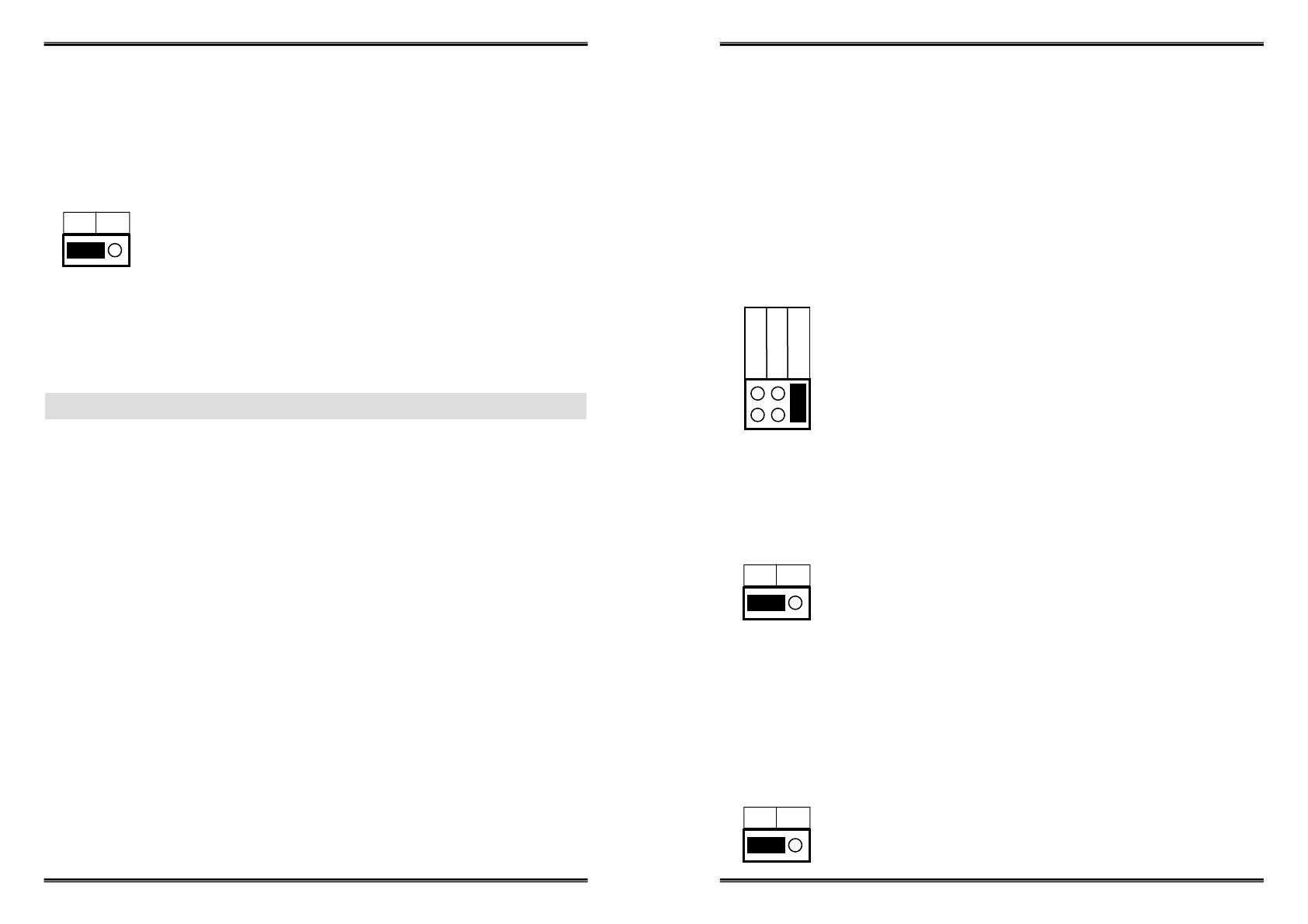
1. Mode Selection Jumper: JP5 for S1 and JP6 for S2
2. Termination Resistor Enable/Disable Jumper: JP7 for S1 and JP8 for S2
3. Echo or No Echo Selection Jumper: JP3 for S1 and JP4 for S2
4. TXD Control Selection Jumper: JP1 for S1 and JP2 for S2
JP5 for S1 Port
JP6 for S2 Port
485-2W = RS-485 Mode with 2-wire (Default)
485-4W = RS-485 Mode with 4-wire
422 = RS-422 Mode
1. Mode Setting for S1 and S2 Ports:
This jumper is to set the transmission data will be echoed back or not. The Echo
mode is useful for the application program to detect if the RS485 bus has collision. If
the echoed data was not equal to the transmitted data, then the bus was in a colli-
sion. This setting only affects the RS485 2-wire mode. It doesn’t affect RS485 4-
wire, RS422, and RS232 modes.
2. Termination Resistor Enable/Disable:
This jumper enables/disables the 120 Ohm termination resistor between DATA+ and
DATA- of the RS485 transceiver:
JP7 for S1 Port
JP8 for S2 Port
OFF ON
OFF = Termination Resistor Disabled (Default)
ON = Termination Resistor Enabled
3. Echo or No Echo Settings:
JP3 for S1 Port
JP4 for S2 Port
OFF ON
OFF = No Echo Data (Default)
ON = Transmission data will be echoed
3.3 Jumper setting