
INSTRUCTION MANUAL
GUIDE D’UTILISATION
MANUAL DE INSTRUCCIONES
INSTRUCTIVO DE OPERACIÓN, CENTROS DE SERVICIO Y PÓLIZA DE
GARANTÍA.
ADVERTENCIA: LÉASE ESTE INSTRUCTIVO ANTES DE
USAR EL PRODUCTO.
DEWALT Industrial Tool Co., 701 Joppa Road, Towson, MD 21286
(MAR14) Part No. N392151 D25501, D25553, D25601, D25603, D25651, D25831, D25851
Copyright © 2010, 2014 D
EWALT
The following are trademarks for one or more D
EWALT power tools: the yellow and black color
scheme; the “D” shaped air intake grill; the array of pyramids on the handgrip; the kit box
configuration; and the array of lozenge-shaped humps on the surface of the tool.
If you have questions or comments, contact us.
Pour toute question ou tout commentaire, nous contacter.
Si tiene dudas o comentarios, contáctenos.
1-800-4-DEWALT • www.dewalt.com
Defi nitions: Safety Guidelines
The definitions below describe the level of severity for each signal word. Please read the
manual and pay attention to these symbols.
DANGER: Indicates an imminently hazardous situation which, if not avoided, will
result in death or serious injury.
WARNING: Indicates a potentially hazardous situation which, if not avoided, could
result in death or serious injury.
CAUTION: Indicates a potentially hazardous situation which, if not avoided, may result
in minor or moderate injury.
NOTICE: Indicates a practice not related to personal injury which, if not avoided, may
result in property damage.
IF YOU HAVE ANY QUESTIONS OR COMMENTS ABOUT THIS OR ANY DEWALT TOOL, CALL
US TOLL FREE AT: 1-800-4-D
EWALT (1-800-433-9258).
WARNING: To reduce the risk of injury, read the instruction manual.
General Power Tool Safety Warnings
WARNING! Read all safety warnings and all instructions. Failure to follow the warnings
and instructions may result in electric shock, fire and/or serious injury.
SAVE ALL WARNINGS AND INSTRUCTIONS
FOR FUTURE REFERENCE
The term “power tool” in the warnings refers to your mains-operated (corded) power tool or
battery-operated (cordless) power tool.
1) WORK AREA SAFETY
a) Keep work area clean and well lit. Cluttered or dark areas invite accidents.
b) Do not operate power tools in explosive atmospheres, such as in the presence of
flammable liquids, gases or dust. Power tools create sparks which may ignite the dust
or fumes.
c) Keep children and bystanders away while operating a power tool. Distractions can
cause you to lose control.
2) ELECTRICAL SAFETY
a) Power tool plugs must match the outlet. Never modify the plug in any way. Do not
use any adapter plugs with earthed (grounded) power tools. Unmodified plugs and
matching outlets will reduce risk of electric shock.
b) Avoid body contact with earthed or grounded surfaces such as pipes, radiators,
ranges and refrigerators. There is an increased risk of electric shock if your body is
earthed or grounded.
c) Do not expose power tools to rain or wet conditions. Water entering a power tool will
increase the risk of electric shock.
d) Do not abuse the cord. Never use the cord for carrying, pulling or unplugging the
power tool. Keep cord away from heat, oil, sharp edges or moving parts. Damaged
or entangled cords increase the risk of electric shock.
e) When operating a power tool outdoors, use an extension cord suitable for outdoor
use. Use of a cord suitable for outdoor use reduces the risk of electric shock.
f) If operating a power tool in a damp location is unavoidable, use a ground fault
circuit interrupter (GFCI) protected supply. Use of a GFCI reduces the risk of electric
shock.
3) PERSONAL SAFETY
a) Stay alert, watch what you are doing and use common sense when operating a
power tool. Do not use a power tool while you are tired or under the influence of
drugs, alcohol or medication. A moment of inattention while operating power tools may
result in serious personal injury.
b) Use personal protective equipment. Always wear eye protection. Protective
equipment such as dust mask, non-skid safety shoes, hard hat, or hearing protection used
for appropriate conditions will reduce personal injuries.
c) Prevent unintentional starting. Ensure the switch is in the off position before
connecting to power source and/or battery pack, picking up or carrying the tool.
Carrying power tools with your finger on the switch or energizing power tools that have the
switch on invites accidents.
d) Remove any adjusting key or wrench before turning the power tool on. A wrench or
a key left attached to a rotating part of the power tool may result in personal injury.
e) Do not overreach. Keep proper footing and balance at all times. This enables better
control of the power tool in unexpected situations.
f) Dress properly. Do not wear loose clothing or jewelry. Keep your hair, clothing and
gloves away from moving parts. Loose clothes, jewelry or long hair can be caught in
moving parts.
g) If devices are provided for the connection of dust extraction and collection
facilities, ensure these are connected and properly used. Use of dust collection can
reduce dust-related hazards.
4) POWER TOOL USE AND CARE
a) Do not force the power tool. Use the correct power tool for your application. The
correct power tool will do the job better and safer at the rate for which it was designed.
b) Do not use the power tool if the switch does not turn it on and off. Any power tool
that cannot be controlled with the switch is dangerous and must be repaired.
c) Disconnect the plug from the power source and/or the battery pack from the
power tool before making any adjustments, changing accessories, or storing
power tools. Such preventive safety measures reduce the risk of starting the power tool
accidentally.
d) Store idle power tools out of the reach of children and do not allow persons
unfamiliar with the power tool or these instructions to operate the power tool.
Power tools are dangerous in the hands of untrained users.
e) Maintain power tools. Check for misalignment or binding of moving parts, breakage
of parts and any other condition that may affect the power tool’s operation. If
damaged, have the power tool repaired before use. Many accidents are caused by
poorly maintained power tools.
f) Keep cutting tools sharp and clean. Properly maintained cutting tools with sharp cutting
edges are less likely to bind and are easier to control.
g) Use the power tool, accessories and tool bits, etc. in accordance with these
instructions, taking into account the working conditions and the work to be
performed. Use of the power tool for operations different from those intended could result
in a hazardous situation.
5) SERVICE
a) Have your power tool serviced by a qualified repair person using only identical
replacement parts. This will ensure that the safety of the power tool is maintained.
Additional Safety Instructions for Rotary Hammers
• Wear ear protectors. Exposure to noise can cause hearing loss.
• Use auxiliary handle(s), if supplied with the tool. Loss of control can cause personal injury.
• Hold power tools by insulated gripping surfaces when performing an operation where
the cutting tool may contact hidden wiring or its own cord. Cutting accessory contacting
a “live” wire may make exposed metal parts of the power tool “live” and could give the
operator an electric shock.
• Use clamps or other practical way to secure and support the workpiece to a stable
platform. Holding the work by hand or against your body is unstable and may lead to loss of
control.
• Wear safety goggles or other eye protection. Hammering operations cause chips to
fly. Flying particles can cause permanent eye damage. Wear a dust mask or respirator for
applications that generate dust. Ear protection may be required for most applications.
• Keep a firm grip on the tool at all times. Do not attempt to operate this tool without
holding it with both hands. Operating this tool with one hand will result in loss of control.
Breaking through or encountering hard materials such as re-bar may be hazardous as well.
Tighten the side handle securely before use.
• Do not operate this tool for long periods of time. Vibration caused by hammer action may
be harmful to your hands and arms. Use gloves to provide extra cushion and limit exposure by
taking frequent rest periods.
• Do not recondition bits yourself. Chisel reconditioning should be done by an authorized
specialist. Improperly reconditioned chisels could cause injury.
• Wear gloves when operating tool or changing bits. Accessible metal parts on the tool and
bits may get extremely hot during operation. Small bits of broken material may damage bare
hands.
• Never lay the tool down until the bit has come to a complete stop. Moving bits could
cause injury.
• Do not strike jammed bits with a hammer to dislodge them. Fragments of metal or
material chips could dislodge and cause injury.
• Keep the power cord away from the rotating bit. Do not wrap the cord around any part
of your body. An electric cord wrapped around a spinning bit may cause personal injury and
loss of control.
• Air vents often cover moving parts and should be avoided. Loose clothes, jewelry or long
hair can be caught in moving parts.
• An extension cord must have adequate wire size (AWG or American Wire Gauge) for
safety. The smaller the gauge number of the wire, the greater the capacity of the cable, that is
16 gauge has more capacity than 18 gauge. An undersized cord will cause a drop in line voltage
resulting in loss of power and overheating. When using more than one extension to make up
the total length, be sure each individual extension contains at least the minimum wire size. The
following table shows the correct size to use depending on cord length and nameplate ampere
rating. If in doubt, use the next heavier gauge. The smaller the gauge number, the heavier the
cord.
Minimum Gauge for Cord Sets
Ampere Rating
Volts Total Length of Cord in Feet (meters)
120V 25 (7.6) 50 (15.2) 100 (30.5) 150 (45.7)
240V 50 (15.2) 100 (30.5) 200 (61.0) 300 (91.4)
More
Than
Not More
Than
AWG
0 6 18 16 16 14
610 18161412
10 12 16 16 14 12
12 16 14 12 Not Recommended
WARNING: ALWAYS use safety glasses. Everyday eyeglasses are NOT safety glasses. Also use
face or dust mask if cutting operation is dusty. ALWAYS WEAR CERTIFIED SAFETY EQUIPMENT:
• ANSI Z87.1 eye protection (CAN/CSA Z94.3),
• ANSI S12.6 (S3.19) hearing protection,
• NIOSH/OSHA/MSHA respiratory protection.
WARNING: Some dust created by power sanding, sawing, grinding, drilling, and other
construction activities contains chemicals known to the State of California to cause cancer, birth
defects or other reproductive harm. Some examples of these chemicals are:
• lead from lead-based paints,
• crystalline silica from bricks and cement and other masonry products, and
• arsenic and chromium from chemically-treated lumber.
Your risk from these exposures varies, depending on how often you do this type of work. To reduce
your exposure to these chemicals: work in a well ventilated area, and work with approved safety
equipment, such as those dust masks that are specially designed to filter out microscopic particles.
• Avoid prolonged contact with dust from power sanding, sawing, grinding, drilling, and
other construction activities. Wear protective clothing and wash exposed areas with
soap and water. Allowing dust to get into your mouth, eyes, or lay on the skin may promote
absorption of harmful chemicals.
WARNING: Use of this tool can generate and/or disperse dust, which may cause serious and
permanent respiratory or other injury. Always use NIOSH/OSHA approved respiratory protection
appropriate for the dust exposure. Direct particles away from face and body.
WARNING: Always wear proper personal hearing protection that conforms to ANSI
S12.6 (S3.19) during use. Under some conditions and duration of use, noise from this product
may contribute to hearing loss.
• The label on your tool may include the following symbols. The symbols and their definitions are
as follows
V .....................volts A .........................amperes
Hz ...................hertz W ........................watts
min .................minutes
or AC .............alternating current
or DC .....direct current or AC/DC......alternating or direct current
...................Class I Construction
n
o .......................no load speed
.......................
.......................(grounded) n .........................rated speed
................... Class II Construction .......................earthing terminal
.......................(double insulated)
........................safety alert symbol
…/min ............per minute BPM ...................beats per minute
IPM .................impacts per minute RPM ...................revolutions per minute
SPM ...............strokes per minute sfpm ...................surface feet per minute
SAVE THESE INSTRUCTIONS FOR FUTURE USE
Motor
Be sure your power supply agrees with the nameplate marking. Voltage decrease of more than
10% will cause loss of power and overheating. DEWALT tools are factory tested; if this tool does
not operate, check power supply.
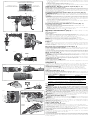
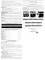
COMPONENTS (Fig. 1)
WARNING: Never modify the power tool or any part of it. Damage or personal injury could result.
A. Trigger switch (D25501, D25553, D25601,
D25603, D25651)
Toggle switch (D25831, D25851)
B. Lock-on slider (D25501, D25553, D25601,
D25603, D25651)
C. Side handle
D. Main handle
E. SHOCKS Active Vibration Control
®
System
(D25651, D25601, D25603, D25831,
D25851)
F. Mode selector
G. Electronic Speed and impact control dial
H. Clamp wheel
I. Rear side handle position
INTENDED USE
These heavy-duty rotary hammers have been designed for professional hammerdrilling, and
chipping at various work sites (i.e., construction sites). DO NOT use under wet conditions or in
presence of flammable liquids or gases.
These heavy-duty rotary hammers are professional power tools. DO NOT let children come into
contact with the tool. Supervision is required when inexperienced operators use this tool.
ASSEMBLY AND ADJUSTMENTS
WARNING: To reduce the risk of injury, turn unit off and disconnect it from power
source before installing and removing accessories, before adjusting or when making
repairs. An accidental start-up can cause injury.
Side Handle (Fig. 1)
D25501, D25553, D25601, D25603, D25851
WARNING: To reduce the risk of personal injury, ALWAYS operate the tool with the side handle
properly installed and securely tightened. Failure to do so may result in the side handle slipping
during tool operation and subsequent loss of control. Hold tool with both hands to maximize
control.
The side handle clamps to the front barrel (collar) and may be rotated 360° to permit right or left-
hand use. For operating convenience, the side handle can be installed in front or rear positions.
TO MOUNT IN FRONT POSITION (FIG. 2)
1. Unscrew the side handle (C) and disassemble the side handle clamp (J).
2. Snap the steel ring (K) over the collar (L) behind the tool holder (M). Squeeze both ends of the
steel ring together. Mount the bushing (N) and insert the pin (O).
3. Slide the side handle clamp (J) onto the bushing (N) while keeping the pin (O) centered. Lightly
screw the clamp wheel (H) onto the busing (N)—do not tighten.
4. Screw the side handle (C) into the clamp knob (H) and tighten.
5. Rotate the side handle mounting assembly to the desired position. For hammerdrilling
horizontally with a heavy drill bit, place the side handle assembly at an angle of approximately
20° to the tool for optimum control.
6. Lock the side handle mounting assembly in place by securely tightening the clamp wheel (H)
so that the assembly will not rotate.
TO MOUNT IN REAR POSITION (FIG. 3)
1. Unscrew the side handle (C) and remove it from the side handle mounting assembly. Leave the
side handle mounting assembly in the front position.
2. Screw the side handle directly into one of the rear side handle positions (I) on either side of the
tool.
D25831, D25851 (FIG. 4)
1. Unscrew the D-shaped handle knob (R).
D25501, D25553 1-9/16" (40 mm) SDS Max and Spline Combination Hammers; D25601, D25603, D25651 1-3/4" (45 mm) SDS Max and
Spline Combination Hammers; D25831, D25851 SDS Max and Spline Chipping Hammers
Marteaux mixtes, SDS Max
®
et cannelures, 40 mm (1-9/16 po), D25501, D25553; Marteaux mixtes, SDS Max et cannelures,
45 mm (1-3/4 po), D25601, D25603, D25651; Marteaux burineurs, SDS Max et cannelures, D25831, D25851
Martillos de 1-9/16" (40 mm) SDS Max y estriados de combinación D25501, D25553; Martillos de 1-3/4" (45 mm) SDS Max y estriados
de combinación D25601, D25603, D25651; Martillos de burilado SDS Max y estriados D25831, D25851

2. Slide the D-shaped handle (Q) and assembly over the tool holder (M) and onto the collar (L) in
the mounting area (Z). The correct position of the D-shaped handle (Q) is between head and
middle of the tube.
3. Adjust the D-shaped handle to the desired angle.
4. Slide and rotate the D-shaped handle to the desired position.
5. Lock the D-shaped handle in place by securely tightening the knob (R) so that the D-shaped
handle assembly will not rotate.
SHOCKS Active Vibration Control
®
System (Fig. 1, 8)
D25651, D25601, D25603, D25831, D25851
For best vibration control, hold the tool with one hand on the main handle (D) and the other hand on
the side handle (C) or D-shaped handle (Q). Apply just enough pressure so the damping device on
the main handle is approximately mid stroke. The hammer only needs enough pressure to engage
the active vibration control. Applying too much pressure will not make the tool drill or chip faster
and active vibration control will not engage.
Inserting and Removing Spline Drive Accessories (Fig. 5)
D25553, D25651, D25851
WARNING: Burn hazard. ALWAYS wear gloves when changing bits. Accessible metal parts on
the tool and bits may get extremely hot during operation. Small bits of broken material may damage
bare hands.
WARNING: Do not attempt to tighten or loosen drill bits (or any other accessory) by gripping the
front part of the chuck and turning the tool on. Damage to the chuck and personal injury may occur.
1. Insert the bit shank into the tool holder (M) as far as it will go. The groove on the chisel shank
(S) must be aligned with the symbol (T) on the toolholder. If inserted correctly, the locking sleeve
(P) moves back to the end position and shows a closed lock symbol.
2. Pull on the bit to be sure that it is properly locked.
3. If the chisel groove is not aligned with the symbol, or is not inserted to the complete depth the
lock symbol remains open.
To remove the bit, pull back the locking sleeve and pull the bit out.
Inserting and Removing SDS Max Accessories (Fig. 6)
D25501, D25601, D25603, D25831
1. Pull back the locking sleeve (P) and insert the bit shank. The bit shank must be clean.
2. Turn the bit slightly until the sleeve snaps back into position.
3. Ensure the bit is properly engaged.
NOTE: The bit needs to move several centimeters in and out of the tool holder (M) when
properly engaged.
4. To remove the bit, pull back the locking sleeve and pull the bit out.
Two-Stage Clutch/E-Clutch
TM
(Fig. 7)
NOTICE: Always turn the tool off before changing torque control settings or damage to tool may
result.
TWO-STAGE CLUTCH
D25603, D25651
Clutch Setting 1 (U) is designed for most hammerdrilling applications and is designed to easily
clutch out when the drill bit encounters re-bar or other foreign substances.
Clutch Setting 2 (V) is designed for higher torque applications such as core-bits and deep hole
hammerdrilling and is designed to clutch out at a higher torque threshold.
Move the torque control lever (Y) to Clutch Setting 1 or 2 as needed for application.
NOTE: Allow the motor housing to rotate a little while changing torque.
NOTE: If it is not possible to select Clutch Setting 2, run the unit under load and try again.
Each time the tool is plugged in, it will automatically default to Clutch Setting 1, the most
sensitive setting.
E-CLUTCH™
D25603
In addition, E-Clutch™ offers increased user comfort and safety through an on-board antirotation
technology capable of detecting if the user loses control of the hammer. When a jam is detected,
the torque and speed are reduced instantly. The red indicator LED (X) illuminates when the
E-Clutch™ is engaged.
Electronic Speed and Impact Control (Fig. 7)
D25651, D25601, D25603, D25831, D25851
The electronic speed and impact control allows the use of smaller drill bits without the risk of bit
breakage, hammerdrilling into light and brittle materials without shattering and optimal tool control
for precise chipping.
To set the control dial, turn the dial (G) to the desired level. The higher the number, the greater
the speed and impact energy. Dial settings make the tool extremely adaptable for many different
appli cations. The required setting depends on the bit size and hardness of material being drilled.
Mode Selector (Fig. 1)
NOTICE: Never change the mode while the unit is running. Tool must come to a complete stop
before activating the mode selector button or damage to the tool may result.
CAUTION: Do not change to hammerdrill mode with chisel bit in tool holder. Personal injury and
damage to tool may result.
The D25501, D25553, D25601 and D25603, D25651 use two operating modes. To select the
required operating mode, rotate the mode selector (F) until the arrow points to the hammerdrilling
or the chipping icon. The D25831 and D25851 use only the chipping mode.
HAMMERDRILLING MODE (
)
D25501, D25553, D25601, D25603, D25651
The tool simultaneously rotates and impacts the work. This mode is appropriate for all concrete
and masonry operations.
CHIPPING MODE (
)
D25831, D25851
The spindle lock is engaged during chipping mode so the tool impacts the work without
rotating. This mode is appropriate for light chipping, chiseling and demolition applications.
NOTE: In chipping mode, the hammerdrill can also be used as a lever to free a jammed drill bit.
CHISEL BIT ADJUSTMENT (
)
Turn the mode selector to one of the chisel bit adjustment icons to adjust the chisel to the
desired position. There are multiple positions to set the angle of the chisel. After finding the
desired position, slightly maneuver the chisel bit back and forth to ensure the chisel is properly
engaged.
Indicator Lights (Fig. 1, 7)
The yellow brush wear indicator LED (W) lights up when the carbon brushes are nearly worn out
indicating that the tool needs servicing within the next 8 hours of use.
The red indicator LED (X) lights up if the lock-on slider (B) and/or E-Clutch™ is engaged in any
mode except the chipping mode.
The red indicator LED (X) starts to flash if there is a fault with the tool or the brushes have completely
worn out (refer to Repairs under Maintenance).
INDICATOR DIAGNOSIS SOLUTION
OFF Tool is functioning normally Follow all warnings and instructions
when operating tool
SOLID Perform and protect control
has been activated
With tool properly supported, release
trigger; the tool will function normally
when the trigger is depressed again
and the indicator light will go out
FLASHING Perform and protect control is
malfunctioning
Take the tool to an authorized
D
EWALT repair agent.
NOTE: If the tool power is insufficient for normal hammering and if the LED does not flash
repeatedly after cycling the trigger, take the tool to an authorized D
EWALT repair center.
OPERATION
WARNING: To reduce the risk of injury, turn unit off and disconnect it from power
source before installing and removing accessories, before adjusting or when making
repairs. An accidental start-up can cause injury.
WARNING: To reduce the risk of personal injury, ALWAYS ensure workpiece is anchored
or clamped firmly. If hammerdrilling thin material, use a wood “back-up” block to prevent damage
to the material.
WARNING: To reduce the risk of personal injury, ALWAYS operate the tool with the
side handle properly installed and securely tightened. Failure to do so may result in the side
handle slipping during tool operation and subsequent loss of control. Hold tool with both hands to
maximize control.
WARNING: Drill may stall if overloaded causing a sudden twist. Always expect the stall. Grip the
drill firmly with both hands to control the twisting action and avoid injury.
Proper Hand Position (Fig. 8)
WARNING: To reduce the risk of serious personal injury, ALWAYS use proper hand position as
shown.
WARNING: To reduce the risk of serious personal injury, ALWAYS hold securely in anticipation
of a sudden reaction.
Proper hand position requires one hand on the side handle (C) or D-shaped handle (Q), with the
other hand on the main handle (D).
NOTE: Operating temperature of this tool is 19˚ to 104˚ F (-7 to +40˚ C). Using the tool outside of
this temperature range will decrease the life of the tool.
Trigger Switch (Fig. 1)
D25501, D25553, D25601, D25603, D25651
To turn the tool on, depress the trigger switch (A). To stop the tool, release the trigger switch.
In chipping mode only, lock the trigger switch on by pushing the lock-on slider (B) upward while
depressing the trigger switch.
To deactivate the lock-on slider, depress the trigger switch once then release.
The lock-on slider may only be activated in chipping mode. The machine will stop running when
trying to engage the lock-on slider in hammerdrilling mode. The motor will stop if the lock-on slider is
activated when changing from chisel mode into hammerdrilling mode.
D25831, D25851
For continuous operation, move the toggle switch (A) to the on position. To stop continuous
operation, move the toggle switch to the off position.
SOFT START FEATURE
The soft start feature allows you to build up speed slowly, thus preventing the drill bit from walking
off the intended hole position when starting. The soft start feature also reduces the immediate
torque reaction transmitted to the gearing and the operator if the hammer is started with the drill
bit in an existing hole.
HAMMERDRILLING MODE
MODE DE MARTEAU PERFORATEUR
MODO TALADRO PERCUTOR
CHIPPING MODE
MODE DE BURINAGE
MODO CINCEL
CHISEL BIT ADJUSTMENT MODE
MODE DE RÉGLAGE DU TRÉPAN ORDINAIRE
MODO DE AJUSTE DE LA BROCA DE CINCEL
CHISEL BIT ADJUSTMENT MODE
MODE DE RÉGLAGE DU TRÉPAN ORDINAIRE
MODO DE AJUSTE DE LA BROCA DE CINCEL
F
E
A
I
G
B
E
C
H
D
FIG. 1
K
J
O
H
C
N
FIG. 2
L
P
M
FIG. 3
C
I
D25603
FIG. 5
M
P
T
S
W
FIG. 7
G
X
U
V
Y
D25501
D25553
D25601
D25603
D25651
Q
D
D25831
D25851
FIG. 8
D
C
FIG. 6
P
Q
R
Z
FIG. 4
D25831
D25851
M
L
M

Hammerdrilling with a Solid Bit (Fig. 1, 7)
D25501, D25553, D25601, D25603, D25651
NOTE: The D25831 and D25851 have only chipping modes with no hammerdrilling capability.
1. Set the mode selector (F) to hammerdrilling mode.
2. For D25603 and D25651 only, move the torque control lever (Y) to Setting 1 (U).
3. Set the speed and impact control dial (G).
4. Insert the appropriate drill bit.
5. Adjust the side handle (front or rear position) (C).
6. Mark the spot where the hole is to be drilled.
7. Place the drill bit on that mark and depress the trigger switch (A).
8. Apply only enough pressure to engage active vibration control (refer to SHOCKS Active
Vibration Control
®
System).
9. To stop the tool, release the trigger switch. Always turn the tool off when work is finished and
before unplugging.
Hammerdrilling with a Core Bit (Fig. 1, 7)
D25501, D25553, D25601, D25603, D25651
CAUTION: Do not use a core bit for hammerdrilling wood. Personal injury and damage to tool
may result.
NOTE: The D25831, D25851 have only chipping modes with no hammerdrilling capability.
1. Set the mode selector (F) to hammerdrilling mode.
2. For D25603 and D25651 only, move the torque control lever (Y) to Setting 2 (V).
3. Turn the speed and impact control dial (G) to the desired speed.
4. Adjust the side handle (front or rear position) (C).
5. Assemble the centering bit and adapter shank into core bit.
6. Mark the spot where the hole is to be drilled.
7. Place the centering bit on that mark and depress the trigger switch (A).
NOTE: Some core drills require the removal of centering bit after about 1 cm of penetration. If
so, remove and continue hammerdrilling.
8. When hammerdrilling through a structure thicker than the depth of the core bit, break away
the round cylinder of concrete or core inside the bit at regular intervals. To avoid unwanted
breaking away of concrete around the hole, first drill a hole the diameter of the centering bit
completely through the structure. Then drill the cored hole halfway from each side of the
structure.
9. To stop the tool, release the trigger switch. Always turn the tool off when work is finished and
before unplugging.
Chipping and Chiseling (Fig. 1)
D25831, D25851
1. Set the mode selector (F) to chipping mode.
2. Set the impact control dial (G) to desired setting (refer to Electronic Speed and Impact
Control).
3. Insert the appropriate chisel and rotate it by hand to lock it into the desired position.
NOTE: For SDS Max models, only use SDS Max bits.
4. Adjust the side handle (front or rear position) (C).
5. Depress the trigger switch (A).
6. Apply only enough pressure to engage active vibration control (refer to SHOCKS Active
Vibration Control
®
System).
7. To stop the tool, release the trigger switch. Always turn the tool off when work is finished and
before unplugging.
MAINTENANCE
WARNING: To reduce the risk of injury, turn unit off and disconnect it from power
source before installing and removing accessories, before adjusting or when making
repairs. An accidental start-up can cause injury.
Cleaning
WARNING: Blow dirt and dust out of all air vents with clean, dry air at least once a week. To
minimize the risk of eye injury, always wear ANSI Z87.1 approved eye protection when performing
this.
WARNING: Never use solvents or other harsh chemicals for cleaning the non-metallic parts
of the tool. These chemicals may weaken the plastic materials used in these parts. Use a cloth
dampened only with water and mild soap. Never let any liquid get inside the tool; never immerse
any part of the tool into a liquid.
Lubrication
Your tool was properly lubricated before leaving the factory. In from two to six months, depending
upon use, take or send your tool to an authorized service center for a complete cleaning, inspection
and lubrication. Tools used constantly on production jobs will need relubrication more often. Also,
tools “out of service” for long periods should be relubricated before being put back to work.
Accessories
WARNING: Since accessories, other than those offered by DEWALT, have not been tested with
this product, use of such accessories with this tool could be hazardous. To reduce the risk of injury,
only D
EWALT recommended accessories should be used with this product.
Recommended accessories for use with your tool are available at extra cost from your local dealer or
authorized service center. If you need assistance in locating any accessory, please contact D
EWALT
Industrial Tool Co., 701 East Joppa Road, Towson, MD 21286, call 1-800-4-D
EWALT (1-800-433-
9258) or visit our website: www.dewalt.com.
MAXIMUM CAPACITY
D25501
D25553
D25601
D25603
D25651 D25831 D25851
Concrete
1-9/16"
(40 mm)
1-3/4"
(45 mm)
1-3/4"
(45 mm)
––
RPM 490 415 415 – –
No load BPM 3300 2840 2840 1430–2840 1430–2840
Repairs
To assure product SAFETY and RELIABILITY, repairs, maintenance and adjustment (including brush
inspection and replacement) should be performed by a D
EWALT factory service center, a DEWALT
authorized service center or other qualified service personnel. Always use identical replacement
parts.
Three Year Limited Warranty
DEWALT will repair, without charge, any defects due to faulty materials or workmanship for three
years from the date of purchase. This warranty does not cover part failure due to normal wear or tool
abuse. For further detail of warranty coverage and warranty repair information, visit www.dewalt.
com or call 1-800-4-D
EWALT (1-800-433-9258). This warranty does not apply to accessories or
damage caused where repairs have been made or attempted by others. This warranty gives you
specific legal rights and you may have other rights which vary in certain states or provinces.
2 YEARS FREE SERVICE
D25601, D25603, D25651, D25831, D25851
D
EWALT will maintain the tool and replace worn parts caused by normal use, for free, any time
during the first year after purchase.
1 YEAR FREE SERVICE
D25501, D25553
DEWALT will maintain the tool and replace worn parts caused by normal use, for free, any time
during the first year after purchase.
90 DAY MONEY BACK GUARANTEE
If you are not completely satisfied with the performance of your D
EWALT Power Tool, Laser, or Nailer
for any reason, you can return it within 90 days from the date of purchase with a receipt for a full
refund – no questions asked.
LATIN AMERICA: This warranty does not apply to products sold in Latin America. For products
sold in Latin America, see country specific warranty information contained in the packaging, call the
local company or see website for warranty information.
FREE WARNING LABEL REPLACEMENT: If your warning labels become illegible or are missing,
call 1-800-4-D
EWALT (1-800-433-9258) for a free replacement.
Défi nitions: lignes directrices en
matière de sécurité
Les définitions ci-dessous décrivent le niveau de danger pour chaque
mot-indicateur employé. Lire le mode d’emploi et porter une attention particulière
à ces symboles.
DANGER : indique une situation dangereuse imminente qui, si elle n’est pas
évitée, entraînera la mort ou des blessures graves.
AVERTISSEMENT: indique une situation potentiellement dangereuse qui,
si elle n’est pas évitée, pourrait entraîner la mort ou des blessures graves.
ATTENTION: indique une situation potentiellement dangereuse qui, si elle
n’est pas évitée, pourrait entraîner des blessures légères ou modérées.
AVIS : indique une pratique ne posant aucun risque de dommages corporels
mais qui par contre, si rien n’est fait pour l’éviter, pourrait poser des risques de
dommages matériels.
POUR TOUTE QUESTION OU REMARQUE AU SUJET DE CET OUTIL OU DE TOUT AUTRE
OUTIL D
EWALT, COMPOSEZ LE NUMÉRO SANS FRAIS : 1-800-4-DEWALT (1-800-433-9258).
AVERTISSEMENT : afin de réduire le risque de blessures, lire le mode d’emploi de l’outil.
Avertissements de sécurité généraux pour les outils
électriques
AVERTISSEMENT ! Lire tous les avertissements de sécurité et toutes les directives.
Le non-respect des avertissements et des directives pourrait se solder par un choc
électrique, un incendie et/ou une blessure grave.
CONSERVER TOUS LES AVERTISSEMENTS ET TOUTES LES
DIRECTIVES POUR UN USAGE ULTÉRIEUR
Le terme « outil électrique » cité dans les avertissements se rapporte à votre outil électrique à
alimentation sur secteur (avec fil) ou par piles (sans fil).
1) SÉCURITÉ DU LIEU DE TRAVAIL
a) Tenir l’aire de travail propre et bien éclairée. Les lieux encombrés ou sombres sont
propices aux accidents.
b) Ne pas faire fonctionner d’outils électriques dans un milieu déflagrant, tel qu’en
présence de liquides, de gaz ou de poussières inflammables. Les outils électriques
produisent des étincelles qui pourraient enflammer la poussière ou les vapeurs.
c) Éloigner les enfants et les personnes à proximité pendant l’utilisation d’un outil
électrique. Une distraction pourrait en faire perdre la maîtrise à l’utilisateur.
2) SÉCURITÉ EN MATIÈRE D’ÉLECTRICITÉ
a) Les fiches des outils électriques doivent correspondre à la prise. Ne jamais modifier
la fiche d’aucune façon. Ne jamais utiliser de fiche d’adaptation avec un outil
électrique mis à la terre. Le risque de choc électrique sera réduit par l’utilisation de fiches
non modifiées correspondant à la prise.
b) Éviter tout contact physique avec des surfaces mises à la terre comme des tuyaux,
des radiateurs, des cuisinières et des réfrigérateurs. Le risque de choc électrique est
plus élevé si votre corps est mis à la terre.
c) Ne pas exposer les outils électriques à la pluie ou à l’humidité. La pénétration de l’eau
dans un outil électrique augmente le risque de choc électrique.
d) Ne pas utiliser le cordon de façon abusive. Ne jamais utiliser le cordon pour
transporter, tirer ou débrancher un outil électrique. Tenir le cordon éloigné de
la chaleur, de l’huile, des bords tranchants et des pièces mobiles. Les cordons
endommagés ou enchevêtrés augmentent les risques de choc électrique.
e) Pour l’utilisation d’un outil électrique à l’extérieur, se servir d’une rallonge
convenant à cette application. L’utilisation d’une rallonge conçue pour l’extérieur réduira
les risques de choc électrique.
f) S’il est impossible d’éviter l’utilisation d’un outil électrique dans un endroit
humide, brancher l’outil dans une prise ou sur un circuit d’alimentation dotés d’un
disjoncteur de fuite à la terre (GFCI). L’utilisation de ce type de disjoncteur réduit les
risques de choc électrique.
3) SÉCURITÉ PERSONNELLE
a) Être vigilant, surveiller le travail effectué et faire preuve de jugement lorsqu’un outil
électrique est utilisé. Ne pas utiliser d’outil électrique en cas de fatigue ou sous
l’influence de drogues, d’alcool ou de médicaments. Un simple moment d’inattention
en utilisant un outil électrique peut entraîner des blessures corporelles graves.
b) Utiliser des équipements de protection individuelle. Toujours porter une protection
oculaire. L’utilisation d’équipements de protection comme un masque antipoussière, des
chaussures antidérapantes, un casque de sécurité ou des protecteurs auditifs lorsque la
situation le requiert réduira les risques de blessures corporelles.
c) Empêcher les démarrages intempestifs. S’assurer que l’interrupteur se trouve à la
position d’arrêt avant de relier l’outil à une source d’alimentation et/ou d’insérer un
bloc-piles, de ramasser ou de transporter l’outil. Transporter un outil électrique alors
que le doigt repose sur l’interrupteur ou brancher un outil électrique dont l’interrupteur est à
la position de marche risque de provoquer un accident.
d) Retirer toute clé de réglage ou clé avant de démarrer l’outil. Une clé ou une clé de
réglage attachée à une partie pivotante de l’outil électrique peut provoquer des blessures
corporelles.
e) Ne pas trop tendre les bras. Conserver son équilibre en tout temps. Cela permet de
mieux maîtriser l’outil électrique dans les situations imprévues.
f) S’habiller de manière appropriée. Ne pas porter de vêtements amples ni de bijoux.
Garder les cheveux, les vêtements et les gants à l’écart des pièces mobiles. Les
vêtements amples, les bijoux ou les cheveux longs risquent de rester coincés dans les pièces
mobiles.
g) Si des composants sont fournis pour le raccordement de dispositifs de dépoussiérage
et de ramassage, s’assurer que ceux-ci sont bien raccordés et utilisés. L’utilisation
d’un dispositif de dépoussiérage peut réduire les dangers engendrés par les poussières.
4) UTILISATION ET ENTRETIEN D’UN OUTIL ÉLECTRIQUE
a) Ne pas forcer un outil électrique. Utiliser l’outil électrique approprié à l’application.
L’outil électrique approprié effectuera un meilleur travail, de façon plus sûre et à la vitesse
pour laquelle il a été conçu.
b) Ne pas utiliser un outil électrique dont l’interrupteur est défectueux. Tout outil
électrique dont l’interrupteur est défectueux est dangereux et doit être réparé.
c) Débrancher la fiche de la source d’alimentation et/ou du bloc-piles de l’outil
électrique avant de faire tout réglage ou changement d’accessoire ou avant de
ranger l’outil. Ces mesures préventives réduisent les risques de démarrage accidentel de
l’outil électrique.
d) Ranger les outils électriques hors de la portée des enfants et ne permettre à
aucune personne n’étant pas familière avec un outil électrique ou son mode
d’emploi d’utiliser cet outil. Les outils électriques deviennent dangereux entre les mains
d’utilisateurs inexpérimentés.
e) Entretien des outils électriques. Vérifier si les pièces mobiles sont mal alignées ou
coincées, si des pièces sont brisées ou présentent toute autre condition susceptible
de nuire au bon fonctionnement de l’outil électrique. En cas de dommage, faire
réparer l’outil électrique avant toute nouvelle utilisation. Beaucoup d’accidents sont
causés par des outils électriques mal entretenus.
f) S’assurer que les outils de coupe sont aiguisés et propres. Les outils de coupe bien
entretenus et affûtés sont moins susceptibles de se coincer et sont plus faciles à maîtriser.
g) Utiliser l’outil électrique, les accessoires, les forets, etc. conformément aux
présentes directives en tenant compte des conditions de travail et du travail à
effectuer. L’utilisation d’un outil électrique pour toute opération autre que celle pour laquelle
il a été conçu est dangereuse.
5) RÉPARATION
a) Faire réparer l’outil électrique par un réparateur professionnel en n’utilisant que
des pièces de rechange identiques. Cela permettra de maintenir une utilisation sécuritaire
de l’outil électrique.
Consignes de sécurité additionnelles propres aux marteaux
rotatifs
• Porter un dispositif de protection auditif. Le bruit en résultant pourrait occasionner une
perte de l’acuité auditive.
• Utiliser la/les poignée(s) auxiliaire(s) si fournie(s) avec l'outil. Une perte de contrôle de
l’outil pourrait occasionner des dommages corporels.
• Tenir l’outil par les surfaces isolées prévues à cet effet pendant toute utilisation où
l’organe de coupe pourrait entrer en contact avec des fils électriques cachés ou son
propre cordon. Tout contact de l’organe de coupe avec un fil sous tension mettra les parties
métalliques exposées de l'outil sous tension et électrocutera l'utilisateur.
• Utiliser des serre-joints, ou tout autre moyen, pour fixer et immobiliser le matériau sur
une surface stable. Tenir la pièce à la main ou contre son corps offre une stabilité insuffisante
qui pourrait vous en faire perdre le contrôle.
• Porter des lunettes de protection ou toute autre protection oculaire. Le martelage
pourrait faire voltiger des éclats. Ces particules volantes pourraient occasionner des dommages
oculaires permanents. Porter un masque anti-poussières ou un appareil de protection des voies
respiratoires pour toute application productrice de poussières. Une protection auditive peut
s’avérer nécessaire pour la plupart des applications.
• Maintenir systématiquement l’outil fermement. Ne pas tenter d’utiliser cet outil sans
le maintenir à deux mains. Le fait d’utiliser cet outil à une main pourra vous en faire perdre le
contrôle. Traverser ou rencontrer des matériaux durs comme les armatures peut aussi s’avérer
dangereux. Resserrer soigneusement la poignée latérale avant toute utilisation.
• Ne pas utiliser cet outil pendant des périodes de temps prolongées. Les vibrations
causées par la percussion peuvent poser des risques pour les mains ou les bras. Porter des
gants pour amortir les vibrations, et pour limiter les risques, faire des pauses fréquentes.
• Ne pas remettre à neuf les forets soi-même. La remise à neuf de tout burin doit être
effectuée par un spécialiste agréé. Tout burin remis à neuf incorrectement pose des risques de
dommages corporels.
• Porter des gants lors de l’utilisation de l’outil ou le changement de mèche. Les parties
métalliques accessibles de l’outil et des mèches/forets pourraient s’avérer brûlantes lors de
l’utilisation. De petits débris de matériau pourraient aussi blesser les mains nues.
• Attendre systématiquement l’arrêt complet de la mèche/foret avant de déposer l’outil
où que ce soit. Des forets/mèches en rotation posent des risques de dommages corporels.
• Ne pas donner des coups de marteau sur des forets/mèches coincés pour les déloger.
Des fragments de métal ou de matériau pourraient être éjectés et causer des dommages
corporels.
• Maintenir le cordon d’alimentation à l’écart d’une mèche en rotation. Ne pas enrouler
le cordon autour d’une partie quelconque de votre corps. Un cordon électrique enroulé
autour d’une mèche en rotation pose des risques de dommages corporels et de perdre le
contrôle de l’outil.
• Prendre des précautions à proximité des évents, car ils cachent des pièces mobiles.
Vêtements amples, bijoux ou cheveux longs risquent de rester coincés dans ces pièces mobiles.
• Pour la sécurité de l’utilisateur, utiliser une rallonge de calibre adéquat (AWG,
American Wire Gauge [calibrage américain normalisé des fils électriques]). Plus le
calibre est petit, et plus sa capacité est grande. Un calibre16, par exemple, a une capacité
supérieure à un calibre18. L’usage d’une rallonge de calibre insuffisant causera une chute de
tension qui entraînera perte de puissance et surchauffe. Si plus d’une rallonge est utilisée pour
obtenir une certaine longueur, s’assurer que chaque rallonge présente au moins le calibre de
fil minimum. Le tableau ci-dessous illustre les calibres à utiliser selon la longueur de rallonge
et l’intensité nominale indiquée sur la plaque signalétique. En cas de doute, utiliser le calibre
suivant. Plus le calibre est petit, plus la rallonge peut supporter de courant.
Calibres minimaux des rallonges
Intensité (en ampères)
volts Longueur totale de cordon en mètres (pieds)
120 V 7,6 (25) 15,2 (50) 30,5 (100) 45,7 (150)
240 V 15,2 (50) 30,5 (100) 61,0 (200) 91,4 (300)
Supérieur à Inférieur à AWG
0 6 18 16 16 14
610 18161412
10 12 16 16 14 12
12 16 14 12 Non recommandé
Page is loading ...
Page is loading ...
Page is loading ...
Page is loading ...
-
 1
1
-
 2
2
-
 3
3
-
 4
4
-
 5
5
-
 6
6
-
 7
7


Ask a question and I''ll find the answer in the document
Finding information in a document is now easier with AI
in other languages
- français: DeWalt D25601K Manuel utilisateur
- español: DeWalt D25601K Manual de usuario