Milwaukee 5426-21 User manual
- Category
- Power drills
- Type
- User manual
This manual is also suitable for
Page is loading ...

2
3
PERSONAL SAFETY
GENERAL POWER TOOL SAFETY WARNINGS
WORK AREA SAFETY
ELECTRICAL SAFETY
• Keep work area clean and well lit. Cluttered or
dark areas invite accidents.
• Do not operate power tools in explosive atmo-
spheres, such as in the presence of fl ammable
liquids, gases or dust. Power tools create
sparks which may ignite the dust or fumes.
• Keep children and bystanders away while
operating a power tool. Distractions can cause
you to lose control.
• Power tool plugs must match the outlet. Never
modify the plug in any way. Do not use any
adapter plugs with earthed (grounded) power
tools. Unmodifi ed plugs and matching outlets will
reduce risk of electric shock.
• Avoid body contact with earthed or grounded
surfaces such as pipes, radiators, ranges and
refrigerators. There is an increased risk of elec-
tric shock if your body is earthed or grounded.
• Do not expose power tools to rain or wet con-
ditions. Water entering a power tool will increase
the risk of electric shock.
• Do not abuse the cord. Never use the cord for
carrying, pulling or unplugging the power tool.
Keep cord away from heat, oil, sharp edges
or moving parts. Damaged or entangled cords
increase the risk of electric shock.
• When operating a power tool outdoors, use
an extension cord suitable for outdoor use.
Use of a cord suitable for outdoor use reduces
the risk of electric shock.
• If operating a power tool in a damp location
is unavoidable, use a residual current device
(RCD) protected supply. Use of an RCD reduces
the risk of electric shock.
medication. A moment of inattention while oper-
ating power tools may result in serious personal
injury.
• Use personal protective equipment. Always
wear eye protection. Protective equipment such
as dust mask, non-skid safety shoes, hard hat, or
hearing protection used for appropriate conditions
will reduce personal injuries.
• Prevent unintentional starting. Ensure the
switch is in the off-position before connecting
to power source and/or battery pack, picking
up or carrying the tool. Carrying power tools
with your fi nger on the switch or energising power
tools that have the switch on invites accidents.
• Remove any adjusting key or wrench before
turning the power tool on. A wrench or a key
left attached to a rotating part of the power tool
may result in personal injury.
• Do not overreach. Keep proper footing and
balance at all times. This enables better control
of the power tool in unexpected situations.
• Dress properly. Do not wear loose clothing or
jewellery. Keep your hair, clothing and gloves
away from moving parts. Loose clothes, jewel-
lery or long hair can be caught in moving parts.
• If devices are provided for the connection of
dust extraction and collection facilities, en-
sure these are connected and properly used.
Use of these devices can reduce dust-related
hazards.
WARNING READ ALL SAFETY WARNINGS AND INSTRUCTIONS.
Failure to follow the warnings and instructions may result in electric shock, fi re and/or
serious injury.
Save all warnings and instructions for future reference
The term "power tool" in all of the warnings refers to your mains-operated (corded) power
tool or battery-operated (cordless) power tool.
POWER TOOL USE AND CARE
• Do not force the power tool. Use the correct
power tool for your application. The correct
power tool will do the job better and safer at the
rate for which it was designed.
• Do not use the power tool if the switch does
not turn it on and off. Any power tool that cannot
be controlled with the switch is dangerous and
must be repaired.
• Disconnect the plug from the power source
and/or the battery pack from the power tool
before making any adjustments, changing
accessories, or storing power tools. Such
preventive safety measures reduce the risk of
starting the power tool accidentally.
• Store idle power tools out of the reach of chil-
dren and do not allow persons unfamiliar with
the power tool or these instructions to operate
the power tool. Power tools are dangerous in the
hands of untrained users.
• Maintain power tools. Check for misalignment
or binding of moving parts, breakage of parts
and any other condition that may affect the
power tool operation. If damaged, have the
power tool repaired before use. Many accidents
are caused by poorly maintained power tools.
• Keep cutting tools sharp and clean. Properly
maintained cutting tools with sharp cutting edges
are less likely to bind and are easier to control.
• Use the power tool, accessories and tool bits
etc., in accordance with these instructions,
taking into account the working conditions
and the work to be performed. Use of the power
tool for operations different from those intended
could result in a hazardous situation.
SERVICE
• Have your power tool serviced by a qualifi ed
repair person using only identical replacement
parts. This will ensure that the safety of the power
tool is maintained.
SPECIFIC SAFETY RULES
• Stay alert, watch what you are doing and use
common sense when operating a power tool.
Do not use a power tool while you are tired
or under the infl uence of drugs, alcohol or
• Wear ear protectors. Exposure to noise can
cause hearing loss.
• Use auxiliary handles supplied with the tool.
Loss of control can cause personal injury.
• Hold power tools by insulated gripping sur-
faces when performing an operation where
the cutting tool may contact hidden wiring or
its own cord. Contact with a “live” wire will make
exposed metal parts of the tool “live” and shock
the operator.
• Keep hands away from all cutting edges and
moving parts.
• Maintain labels and nameplates. These carry
important information. If unreadable or missing,
contact a MILWAUKEE service facility for a free
replacement.
• WARNING: Some dust created by power sand-
ing, sawing, grinding, drilling, and other construc-
tion activities contains chemicals known to cause
cancer, birth defects or other reproductive harm.
Some examples of these chemicals are:
• lead from lead-based paint
• crystalline silica from bricks and cement and other
masonry products, and
• arsenic and chromium from chemically-treated
lumber.
Your risk from these exposures varies, depend-
ing on how often you do this type of work. To
reduce your exposure to these chemicals: work
in a well ventilated area, and work with approved
safety equipment, such as those dust masks that
are specially designed to fi lter out microscopic
particles.
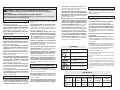
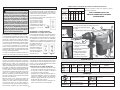
BPM
Blows per Minute (BPM)
Volts Alternating Current
Amps
No Load Revolutions per
Minute (RPM)
Underwriters Laboratories, Inc.,
United States and Canada
Mexican Approvals Marking
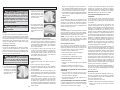
Symbology
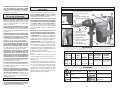
Specifi cations
No Load
RPM
350 / 450
- -
No Load
Blows per
Minute
2200 / 2840
2200 / 2840
Cat.
No.
5426-21
5446-21
Carbide Tipped
Percussion Bit
(concrete)
1-3/4"
- -
Tool
Capacities
Volts
AC
120
120
Amps
14
14
Percussion
Core Bit
(concrete/brick)
4-1/2" / 6"
- -
Shank
Type
SDS-Max
SDS-Max

4
5
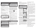
grounding system and must never be attached to
an electrically “live” terminal.
Your tool must be plugged into an appropriate out-
let, properly installed and grounded
in accordance with all codes and or-
dinances. The plug and outlet should
look like those in Figure A.
Double Insulated Tools:
Tools with Two Prong Plugs
Tools marked “Double Insulated” do not require
grounding. They have a special double insula-
tion system which satisfi es OSHA requirements
and complies with the applicable standards of
Underwriters Laborato-
ries, Inc., the Canadian
Standard Association
and the National Elec-
trical Code. Double In-
sulated tools may be
used in either of the 120
volt outlets shown in
Figures B and C.
Fig. B
Fig. C
Fig. A
GROUNDING
WARNING Improperly connecting the
grounding wire can result in the risk of elec-
tric shock. Check with a qualifi ed electrician
if you are in doubt as to whether the outlet is
properly grounded. Do not modify the plug
provided with the tool. Never remove the
grounding prong from the plug. Do not use
the tool if the cord or plug is damaged. If
damaged, have it repaired by a MILWAUKEE
service facility before use. If the plug will not
fi t the outlet, have a proper outlet installed by
a qualifi ed electrician.
Grounded Tools:
Tools with Three Prong Plugs
Tools marked “Grounding Required” have a three
wire cord and three prong grounding plug. The
plug must be connected to a properly grounded
outlet (See Figure A). If the tool should electrically
malfunction or break down, grounding provides a
low resistance path to carry electricity away from
the user, reducing the risk of electric shock.
The grounding prong in the plug is connected
through the green wire inside the cord to the
grounding system in the tool. The green wire in the
cord must be the only wire connected to the tool's
Grounded tools require a three wire extension
cord. Double insulated tools can use either a two
or three wire extension cord. As the distance from
the supply outlet increases, you must use a heavier
gauge extension cord. Using extension cords with
inadequately sized wire causes a serious drop in
voltage, resulting in loss of power and possible tool
damage. Refer to the table shown to determine the
required minimum wire size.
The smaller the gauge number of the wire, the
greater the capacity of the cord. For example, a 14
gauge cord can carry a higher current than a 16
gauge cord. When using more than one extension
cord to make up the total length, be sure each cord
contains at least the minimum wire size required. If
you are using one extension cord for more than one
tool, add the nameplate amperes and use the sum
to determine the required minimum wire size.
READ AND SAVE ALL
INSTRUCTIONS FOR
FUTURE USE.
Recommended Minimum Wire Gauge
for Extension Cords*
Extension Cord Length
* Based on limiting the line voltage drop to
fi ve volts at 150% of the rated amperes.
Nameplate
Amperes
0 - 2.0
2.1 - 3.4
3.5 - 5.0
5.1 - 7.0
7.1 - 12.0
12.1 - 16.0
16.1 - 20.0
25'
18
18
18
18
16
14
12
75'
18
18
16
14
12
10
100'
18
16
14
12
10
150'
16
14
12
12
50'
18
18
18
16
14
12
10
EXTENSION CORDS
Guidelines for Using Extension Cords
• If you are using an extension cord outdoors,
be sure it is marked with the suffi x “W-A” (“W”
in Canada) to indicate that it is acceptable for
outdoor use.
• Be sure your extension cord is properly wired
and in good electrical condition. Always replace
a damaged extension cord or have it repaired by
a qualifi ed person before using it.
• Protect your extension cords from sharp objects,
excessive heat and damp or wet areas.
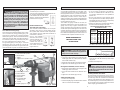
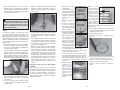
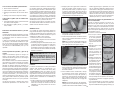
FUNCTIONAL DESCRIPTION
1. Bit holder
2 Rear side handle position
3. Mode selector
4. Trigger
5. Trigger lock-on (5446-21 only)
12
11
9
1
3
4
6
8
7
2
10
5
6. Hammer speed control
7. Power indicator
8. Service indicator
9. Side handle
10. Side handle ball
(5446-21 only)
11. Clamp
12. Depth gauge rod
ASSEMBLY
WARNING To reduce the risk of in-
jury, always unplug tool before changing or
removing accessories. Only use accessories
specifi cally recommended for this tool. Others
may be hazardous.
Adjusting the Side Handle Position
1. Loosen the side handle by unscrewing the side
handle grip (5426-21) or ball (5446-21) until the
side handle rotates freely.
2. Rotate the side handle to the desired position.
3. Tighten the side handle grip or ball securely.
Moving the Side Handle (Cat. No. 5426-21)
1. Remove the side handle by unscrewing the side
handle grip until it comes free.
2. Screw the side handle into the alternate loca-
tion.
3. Tighten the side handle grip securely.
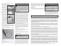
Setting the Depth Gauge
1. Press in the clamp lever.
2. Slide the depth gauge rod backward or forward
until it is set for the desired depth.
Fig. 1
Drilling Depth
Installing Drill Bits and Chisels
Be sure that the shank of the bit is clean. Dirt par-
ticles may cause the bit to line up improperly. Do not
use bits larger than the maximum recommended
capacity of the drill because gear damage or mo-
tor overloading may result. For best performance,
be sure that the bit is properly sharpened and the
shank is lightly greased before use.
NOTE: The drilling depth is the distance be-
tween the tip of the bit and the tip of the depth
gauge rod.
3. Release the clamp lever.
WARNING To reduce the risk of injury,
always use a side handle when using this tool.
Always brace or hold securely.

6
7
WARNING To reduce the risk of injury,
wear safety goggles or glasses with side
shields.
WARNING To reduce the risk of injury,
always unplug tool before attaching or remov-
ing accessories or making adjustments. Use
only specifi cally recommended accessories.
Others may be hazardous. Keep hands away
from the bit and all moving parts.
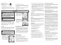
OPERATION
SDS Drive System
NOTE: Only use accessories
with SDS or SDS Plus shanks.
1. Unplug the tool.
2. Lightly grease the bit or chisel shank.
3. Insert the bit or chisel into the nose of the tool.
4. Rotate bit slowly until it aligns with the locking
mechanism.
5. Push bit into tool until it locks.
6. Check that the bit is locked properly; it should
be possible to pull the bit back and forth slightly
(about 1/4”).
7. To remove bits and chisels, pull bit holder toward
the rear of tool and remove bit.
NOTE: Use caution when handling hot bits and
chisels.
2. For hammering only,
turn the selector lever
to display the hammer
symbol. (See "Selecting
Hammering Speed")
3. To freely rotate the bit
to the desired angle for
chiseling only, turn the
selector lever to display
the 0 symbol.
Power and Service Indicators
When the tool is plugged in, the Power Indicator will
light. Unplug the tool before changing accessories
or making adjustments.
When the tool is in need of service (for example,
brushes need to be changed), the Service Indica-
tor will light. Stop using the tool and return it to the
nearest MILWAUKEE service facility for repairs.
Operating and Operator Force
Position the tool, grasp the handles fi rmly and pull
the trigger. Always hold the tool securely using both
handles to maintain control.
These hammers feature the Anti-Vibration System
to provide the operator with comfort without sacrifi c-
ing power or performance. Insulating elements ab-
sorb vibration when hammering and drilling. Ideal
operator force compresses the handle slightly
and allows the tool to work aggressively while the
handle provides maximum vibration dampening.
Excessive operator force compresses the handle
too far and reduces the vibration dampening. Users
will be able to feel the difference and should adjust
the force to the handle accordingly.
A smooth, even fl ow of dust indicates the proper
drilling rate. If the speed begins to drop off when
drilling large or deep holes, pull the bit partially out
of the hole while the tool is running to help clear
dust. Do not use water to settle the dust since it
will clog the bit fl utes and tend to make the bit
bind in the hole. If the bit should bind, a built-in,
non-adjustable slip clutch prevents the bit from
turning. If this occurs, stop the tool, free the bit
and begin again.
Do not let the bit spin in the hole without cutting. Do
not attempt to drill through steel reinforcing rods.
Both actions will damage the carbide.
Cold Hammering
If the hammer is stored for a long period of time or
at cold temperatures, the lubrication may become
stiff and the tool may not hammer initially or the
hammering may be weak. If this happens:
1. Insert a chisel into the tool.
2. Pull the trigger and apply the chisel against a
scrap piece of concrete.
3. Turn the tool On and Off every few seconds.
After 15 seconds to 2 minutes, the tool will start
hammering normally. The colder the hammer is,
the longer it will take to warm up.
Fig. 2
Fig. 3
Fig. 4
Electronic Feedback Control Circuit
These hammers have an Electronic Feedback
Control Circuit (EFCC) which helps improve the
operation and life of the tool. It allows the tool to
maintain constant speed and torque between no-
load and load conditions.
Soft Start
The Soft-Start feature reduces the amount of torque
reaction at startup to the tool and the user. This
feature gradually increases the motor speed up
from zero to the top no-load speed.
6. Use only enough pressure to hold the tool in
place, engage the hammering mechanism,
and prevent the tip of the chisel from wander-
ing. This tool has been designed to achieve top
performance with only moderate pressure. Let
the tool do the work.
NOTE: To engage the hammering mechanism,
maintain pressure on the bit/chisel. When pres-
sure is released, hammering stops.
7. To stop the tool, release the trigger. Make sure
the tool comes to a complete stop before laying
the tool down.
Chiseling
When chiseling or chipping, hold the tool at an
angle to the work area. For best performance, work
from a corner or close the edge of the work and
break off a small area at a time.
Drilling
When drilling deep holes, the speed may begin to
drop off. Pull the bit partially out of the hole while
the tool is running to help clear dust.
NOTE: Do not use water to settle the dust since
it will clog the bit fl utes and tend to make the bit
bind in the hole.
If a bit binds:
If the bit should bind, a built in, nonadjustable slip
clutch prevents the bit from turning when the tool
is held or braced securely. If this occurs
1. Turn off and unplug the tool.
2. Free the bit from the workpiece.
3. Clear debris from the hole.
4. Begin drilling again.
If a hammer iron gets stuck:
1. Unplug the tool.
2. Pull out bit lock and rotate it 180°.
3. Pull the tool off of the stuck accessory.
4. Remove the accessory from the workpiece.
Locking Trigger (Cat. No. 5446-21 only)
1. To lock on the trigger, pull the trigger and press
the lock button. Release the trigger.
2. To unlock the trigger, pull and release the trig-
ger.
WARNING To reduce the risk of injury,
when using chisels or other hammering-only
accessories, the action selector must be set
to the "hammering only" position.
Selecting Mode
1. For hammering with
rotation, turn the selec-
tor lever to display the
hammer and twist drill
symbols. (Not available
on Cat. No. 5446-21)
Selecting Hammering Speed
1. To increase the Hammering speed (2840 blows
per second), move the hammer speed control se-
lector to the large hammer. Use the high hammer
speed for harder materials, such as concrete.
2. To decrease the Hammering speed (2200 blows
per second), move the hammer speed control
selector to the small hammer. Use the low ham-
mer speed for softer materials, such as brick.
Starting and Stopping
1. Insert the accessory
2. Select the mode and hammering speed.
3. Position the tool on the workpiece.
4. Grasp both handles fi rmly (trigger handle and
either the spade handle or straight handle).
5. To start the tool, grasp the handles fi rmly and
pull the trigger. Always hold the tool securely
using two handles and maintain control.

8
9
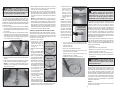
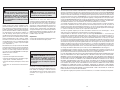
Using Rotary Percussion Core Bits
Core bits are useful for drilling larger holes for
conduit and pipe. MILWAUKEE Heavy-Duty Core
Bits have heat-treated steel bodies with durable
carbide tips. These core bits are specially designed
for fast, accurate drilling with combined hammering
and rotary action.
1. Clean and lubricate the threads on the adapter
and core bit to make later removal easier. Screw
the threaded end of the adapter into the rear of
the core bit.
2. Push the guide plate onto the pointed end of the
center pin. Insert the center pin and guide plate
assembly into the core bit. Be sure the small end
of the center pin is securely placed into the hole
in the center of the core bit (Fig. 5).
Fig. 5
3. Insert the adapter into the nose of the tool. Set
the action selector to the hammering with rotation
setting.
4. Press the center pin fi rmly against your center
mark, hold the tool fi rmly and pull the trigger.
NOTE: If a center pin and guide plate are not
available, use a template or notched board to
start the hole (Fig. 6).
Fig. 6
5. After drilling to about the depth of the core bit
teeth, remove the center pin and guide plate
from the core bit. Resume drilling.
6. To change the core bit, hold the tool upwards,
pointing it away from your body, and run the tool
allowing rotation and impacting for about fi ve
seconds to loosen the core bit from the adapter
shank.
NOTE: To make deeper holes, remove the core
bit, break and remove the core. Resume drilling.
When drilling long or deep holes, after each inch
of penetration pull the bit partially out of the hole
while the tool is running, to help clear dust from
the bit fl utes. Dust can clog the bit fl utes and can
make the bit bind in the hole. If this occurs, stop
the tool, free the bit and begin again.
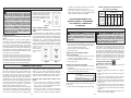
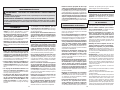
Drilling Large Diameter Holes with Core Bits
When drilling holes with large diameter core bits,
dust may build up in the cut and can cause the tool
to stall, bind, or cut slowly. By creating an opening
for the dust to escape, drilling time, bit stress, and
tool stress can be reduced.
1. Start the cut as normal.
2. Once the bit is firmly
established in the cut
(about 1/4" deep), re-
move the bit from the
cut (Fig. 7).
3. Remove the bit from the
tool.
4. Install a standard fl uted
bit, approximately 7/8" in
diameter, onto the tool.
5. Drill a perpendicular
hole through the kerf of
the large hole (Fig. 8).
• Depending on the loca-
tion of the work, the
hole should either break
through the other side of
the hole/fl oor or extend
4"-5" past the end of
the workpiece (such
as into the dirt below
a concrete slab).
• If dust builds up in the
hole, vacuum it out and
continue drilling.
• If drilling through a
wall, the hole for dust
should be drilled on the
lowest part of the large
hole kerf (Fig. 9) as the dust will fall there when
drilling and can be evacuated more easily.
Fig. 7
Cut approximately
1/4" deep with a
core bit.
Fig. 10
Side view
of slab
Fig. 11
Pull bit out as
far as possible
once or twice
per inch drilled.
Fig. 12
WARNING Use MILWAUKEE core bits.
Do not use LHS (Large Hole System) Com-
ponents with these rotary hammers. The bits
could fail, breaking apart at the threaded stud
and causing injury and property damage.
Fig. 8
Drill a hole
through the work.
Fig. 9
Dust and debris
will fall through
the hole.
Top view
6. Reinstall the core
bit and continue
drilling (Fig. 9 &
10). Dust and
debris will fall
through the hole
and optimize the
cutting ability of
the bit.
NOTE: If unable to
drill a hole in the kerf,
pull back on the bit
with the hammer run-
ning (Fig. 11). This
will remove some of
the dust and debris
from the cut. Repeat
this for every inch of
drilling. If necessary,
vacuum dust and de-
bris from the cut and
surrounding area.
7. For core bits, once the maximum core bit
depth is drilled, the core must be broken and
removed (Fig. 12).
• Install a chisel bit.
• Place the chisel into the hole kerf.
• Chisel down into the kerf at several points until
the core is loose or broken.
• Remove the core and vacuum/remove any
remaining dust and debris.
• Install the core bit and continue the cut.
Maintaining Tools
Keep your tool in good repair by adopting a regular
maintenance program. Before use, examine the
general condition of your tool. Inspect guards,
switches, tool cord set and extension cord for
damage. Check for loose screws, misalignment,
binding of moving parts, improper mounting, bro-
ken parts and any other condition that may affect
its safe operation. If abnormal noise or vibration
occurs, turn the tool off immediately and have the
problem corrected before further use. Do not use a
damaged tool. Tag damaged tools “DO NOT USE”
until repaired (see “Repairs”).
Under normal conditions, relubrication is not neces-
sary until the motor brushes need to be replaced.
After six months to one year, depending on use,
return your tool to the nearest MILWAUKEE service
facility for the following:
• Lubrication
• Brush inspection and replacement
• Mechanical inspection and cleaning (gears,
spindles, bearings, housing, etc.)
• Electrical inspection (switch, cord, armature, etc.)
• Testing to assure proper mechanical and electri-
cal operation
Cleaning
Clean dust and debris from vents. Keep the tool
handles clean, dry and free of oil or grease. Use
only mild soap and a damp cloth to clean your tool
since certain cleaning agents and solvents are
harmful to plastics and other insulated parts. Some
of these include: gasoline, turpentine, lacquer thin-
ner, paint thinner, chlorinated cleaning solvents,
ammonia and household detergents containing
ammonia. Never use fl ammable or combustible
solvents around tools.
Repairs
If your tool is damaged, return the entire tool to the
nearest service center.
MAINTENANCE
WARNING To reduce the risk of
injury, always unplug your tool before
performing any maintenance. Never disas-
semble the tool or try to do any rewiring
on the tool’s electrical system. Contact a
MILWAUKEE service facility for ALL repairs.
WARNING To reduce the risk of injury,
electric shock and damage to the tool, never
immerse your tool in liquid or allow a liquid
to fl ow inside the tool.

10
11
ACCESSORIES
For a complete listing of accessories refer to your
MILWAUKEE Electric Tool catalog or go on-line
to www.milwaukeetool.com. To obtain a catalog,
contact your local distributor or a service center.
WARNING To reduce the risk of injury,
always unplug the tool before attaching or
removing accessories. Use only specifi cally
recommended accessories. Others may be
hazardous.
FIVE YEAR TOOL LIMITED WARRANTY
Every MILWAUKEE electric power tool (including battery charger) is warranted to the original purchaser
only to be free from defects in material and workmanship. Subject to certain exceptions, MILWAUKEE will
repair or replace any part on a electric power tool which, after examination, is determined by MILWAUKEE
to be defective in material or workmanship for a period of fi ve (5) years* after the date of purchase. Return
the electric power tool and a copy of proof of purchase to a MILWAUKEE factory Service/Sales Support
Branch location or MILWAUKEE Authorized Service Station, freight prepaid and insured, are requested
for this warranty to be effective. This warranty does not apply to damage that MILWAUKEE determines
to be from repairs made or attempted by anyone other than MILWAUKEE authorized personnel, misuse,
alterations, abuse, normal wear and tear, lack of maintenance, or accidents.
* The warranty period for Hoists (lever, hand chain, & electric chain hoists), all Ni-CD battery packs, Work
Lights (cordless fl ashlights), Job Site Radios, and Trade Titan™ Industrial Work Carts is one (1) year from
the date of purchase. *The warranty period for Li-Ion battery packs that do not contain V™-technology –
4.0 volts through 18.0 volts - is two (2) years from the date of purchase.
*There is a separate warranty for V™-technology Li-Ion Battery Packs V™18 volts and above that ac-
company V™-technology cordless power tools:
*Every MILWAUKEE V™-technology Li-Ion Battery Pack 18 volts or above is covered by an initial 1000
Charges/2 Years free replacement warranty. This means that for the earlier of the fi rst 1000 charges or
two (2) years from the date of purchase/fi rst charge, a replacement battery will be provided to the customer
for any defective battery free of charge. Thereafter, customers will also receive an additional warranty on
a pro rata basis up to the earlier of the fi rst 2000 charges or fi ve (5) Years from the date of purchase/fi rst
charge. This means that every customer gets an additional 1000 charges or three (3) years of pro rata
warranty on the V™-technology Li-Ion Battery Pack 18 volts or above depending upon the amount of use.
During this additional warranty period, the customer pays for only the useable service received over and
above the fi rst 1000 Charges/2 years, based on the date of fi rst charge and number of charges found on
the battery pack via Milwaukee’s V™-technology Service Reader.
Warranty Registration is not necessary to obtain the applicable warranty on a MILWAUKEE product. The
manufacturing date of the product will be used to determine the warranty period if no proof of purchase is
provided at the time warranty service is requested.
ACCEPTANCE OF THE EXCLUSIVE REPAIR AND REPLACEMENT REMEDIES DESCRIBED HEREIN
IS A CONDITION OF THE CONTRACT FOR THE PURCHASE OF EVERY MILWAUKEE PRODUCT.
IF YOU DO NOT AGREE TO THIS CONDITION, YOU SHOULD NOT PURCHASE THE PRODUCT. IN
NO EVENT SHALL MILWAUKEE BE LIABLE FOR ANY INCIDENTAL, SPECIAL, CONSEQUENTIAL OR
PUNITIVE DAMAGES, OR FOR ANY COSTS, ATTORNEY FEES, EXPENSES, LOSSES OR DELAYS
ALLEGED TO BE AS A CONSEQUENCE OF ANY DAMAGE TO, FAILURE OF, OR DEFECT IN ANY
PRODUCT INCLUDING, BUT NOT LIMITED TO, ANY CLAIMS FOR LOSS OF PROFITS. THIS WAR-
RANTY IS EXCLUSIVE AND IN LIEU OF ALL OTHER WARRANTIES OR CONDITIONS, WRITTEN OR
ORAL, EXPRESSED OR IMPLIED. WITHOUT LIMITING THE GENERALITY OF THE FOREGOING,
MILWAUKEE DISCLAIMS ANY IMPLIED WARRANTY OF MERCHANTABILITY OR FITNESS FOR A
PARTICULAR USE OR PURPOSE, AND ALL OTHER WARRANTIES.
This warranty applies to product sold in the U.S.A., Canada and Mexico only.
Please consult the ‘Service Center Search’ in the Parts & Service section of MILWAUKEE’s web-site www.
milwaukeetool.com or call 1.800.SAWDUST (1.800.729.3878) to locate your nearest service facility for
warranty and non-warranty service on a MILWAUKEE electric power tool.
RÈGLES DE SÉCURITÉ GÉNÉRALES RELATIVES AUX
OUTILS ÉLECTRIQUES
AVERTISSEMENT
LIRE TOUTES LES RÈGLES ET INSTRUCTIONS DE SÉCURITÉ.
Ne pas suivre l’ensemble des règles et instructions peut entraîner une électrocution, un
incendie ou des blessures graves.
Conserver les règles et les instructions à des fi ns de référence ultérieure.
Le terme «outil électrique» fi gurant dans les avertissements ci-dessous renvoie à l’outil élec-
trique à alimentation par le réseau (à cordon) ou par batterie (sans fi l).
• Maintenir la zone de travail propre et bien
éclairée. Les zones encombrées ou mal éclai-
rées sont favorables aux accidents.
• Ne pas utiliser d’outil électrique dans une at-
mosphère explosive, telle qu’en en présence
de liquides, de gaz ou de poussières infl am-
mables. Les outils électriques génèrent des
étincelles qui peuvent enfl ammer les poussières
ou les fumées.
• Tenir les enfants et les personnes non auto-
risées à l’écart pendant le fonctionnement
d’un outil électrique. Un manque d’attention de
l’opérateur risque de lui faire perdre le contrôle
de l’outil.
• La fi che de l’outil électrique doit correspondre
à la prise d’alimentation. Ne jamais modifi er la
fi che d’une manière quelconque. Ne pas uti-
liser d’adaptateur avec les outils électriques
mis à la terre (à la masse). Des fi ches non
modifi ées et des prises d’alimentation assorties
réduisent le risque de choc électrique.
• Éviter tout contact corporel avec des surfaces
reliées à la masse ou à la terre telles que tuy-
aux, radiateurs, cuisinières et réfrigérateurs.
Un risque de choc électrique plus élevé existe si
le corps est relié à la masse ou à la terre.
• Ne pas exposer les outils électriques à la pluie
ou à l’humidité. Le risque de choc électrique
augmente si de l’eau s’infi ltre dans un outil élec-
trique.
• Prendre soin du cordon. Ne jamais utiliser le
cordon pour transporter, tirer ou débrancher
l’outil électrique. Tenir le cordon à l’écart de
la chaleur, des huiles, des arêtes coupantes
ou des pièces en mouvement. Un cordon en-
dommagé ou emmêlé présente un risque accru
de choc électrique.
• Se procurer un cordon d’alimentation ap-
proprié en cas d’utilisation d’un outil élec-
trique à l’extérieur. L’utilisation d’un cordon
• Être sur ses gardes, être attentif et faire
preuve de bon sens en utilisant un outil
électrique. Ne pas utiliser un outil électrique
en cas de fatigue ou sous l’influence de
drogues, d’alcool ou de médicaments. Un
instant d’inattention lors de l’utilisation d’un outil
électrique peut entraîner des blessures graves.
• Porter l’équipement de protection requis.
Toujours porter une protection oculaire.
Selon les conditions, porter aussi un masque
anti-poussières, des bottes de sécurité antidéra-
pantes, un casque protecteur ou une protection
auditive afi n de réduire les blessures.
• Empêcher les démarrages accidentels.
S’assurer que la gâchette est en position
d’arrêt avant de brancher l’outil à une source
de courant, d’insérer la batterie, de le ramass-
er ou de le transporter. Le fait de transporter
l’outil en gardant le doigt sur la gâchette ou de
le brancher lorsque la gâchette est en position
de marche favorise les accidents.
• Retirer toute clé de réglage avant de mettre
l’outil sous tension. Une clé laissée attachée
sur une pièce mobile de l’outil électrique peut
entraîner des blessures.
• Ne pas travailler à bout de bras. Bien garder
un bon équilibre à tout instant. Ceci permet de
mieux préserver la maîtrise de l’outil électrique
dans des situations imprévues.
• Porter des vêtements adéquats. Ne pas porter
de vêtements amples ni de bijoux. Ne pas ap-
procher les cheveux, vêtements et gants des
pièces en mouvement. Les vêtements amples,
les bijoux ou les cheveux longs risquent d’être
happés par les pièces en mouvement.
d’alimentation pour usage extérieur réduit le
risque de choc électrique.
• S’il est nécessaire d’utiliser l’outil électrique
dans un endroit humide, installer un appareil
à courant résiduel (RCD). L’utilisation d’un RCD
réduit le risque de décharge électrique.
SÉCURITÉ INDIVIDUELLE
SÉCURITÉ ÉLECTRIQUE
SÉCURITÉ DU LIEU DE TRAVAIL
Page is loading ...
Page is loading ...
Page is loading ...
Page is loading ...
Page is loading ...
Page is loading ...
Page is loading ...
Page is loading ...
Page is loading ...
Page is loading ...

32
MILWAUKEE ELECTRIC TOOL CORPORATION
13135 West Lisbon Road • Brookfi eld, Wisconsin, U.S.A. 53005
58-14-5426d2 08/08 Printed in USA
UNITED STATES - MILWAUKEE Service
MILWAUKEE prides itself in producing a premium
quality product that is NOTHING BUT HEAVY DUTY
®
.
Your satisfaction with our products is very impor-
tant to us! If you encounter any problems with the
operation of this tool, or you would like to locate the
factory Service/Sales Support Branch or authorized
service station nearest you, please call...
Canada - Service MILWAUKEE
Milwaukee Electric Tool, S.A. de C.V.
Blvd. Abraham Lincoln no. 13
Colonia Los Reyes Zona Industrial
Tlalnepantla, Edo. México C.P. 54073
Tel. (55) 5565-1414 Fax: (55) 5565-6874
Adicionalmente, tenemos una red nacional de dis-
tribuidores autorizados listos para ayudarle con su
herramienta y sus accesorios. Por favor, llame al (55)
5565-1414 para obtener los nombres y direcciones
de los más cercanos a usted, o consulte la sección
‘Where to buy’ (Dónde comprar) de nuestro sitio web en
www.milwaukeetool.com
Registre su herramienta en línea, en
www.milwaukeetool.com y...
• reciba importantes avisos sobre su compra
• asegúrese de que su herramienta esté
protegida por la garantía
• conviértase en integrante de Heavy Duty
MILWAUKEE est fi er de proposer un produit de pre-
mière qualité N
OTHING BUT HEAVY DUTY
®
. Votre satisfac-
tion est ce qui compte le plus!
En cas de problèmes d’utilisation de l’outil ou pour loca-
liser le centre de service/ventes ou le centre d’entretien
le plus proche, appelez le...
416.439.4181
fax: 416.439.6210
Milwaukee Electric Tool (Canada) Ltd
755 Progress Avenue
Scarborough, Ontario M1H 2W7
Notre réseau national de distributeurs agréés se
tient à votre disposition pour fournir l’aide technique,
l’outillage et les accessoires nécessaires. Composez
le 416.439.4181 pour obtenir les noms et adresses
des revendeurs les plus proches ou bien consultez la
section «Où acheter» sur notre site web à l’adresse
www.milwaukeetool.com
MEXICO - Soporte de Servicio
MILWAUKEE
1-800-SAWDUST
(1.800.729.3878)
Monday-Friday
7:00 AM - 6:30 PM
Central Time
or visit our website at
www.milwaukeetool.com
Additionally, we have a nationwide network of
authorized Distributors ready to assist you with
your tool and accessory needs. Check your “Yellow
Pages” phone directory under “Tools-Electric” for
the names & addresses of those nearest you or see
the 'Where To Buy' section of our website.
Contact our Corporate After Sales Service
Technical Support about ...
•Technical Questions
•Service/Repair Questions
•Warranty
call: 1-800-SAWDUST
fax: 1.800.638.9582
email: [email protected]
Register your tool online at
www.milwaukeetool.com and...
• receive important notifi cations regarding
your purchase
• ensure that your tool is protected under the
warranty
• become a HEAVY DUTY club member
For service information, use the 'Service Center
Search' icon found in the 'Parts & Service' section.
-
 1
1
-
 2
2
-
 3
3
-
 4
4
-
 5
5
-
 6
6
-
 7
7
-
 8
8
-
 9
9
-
 10
10
-
 11
11
-
 12
12
-
 13
13
-
 14
14
-
 15
15
-
 16
16
-
 17
17


Milwaukee 5426-21 User manual
- Category
- Power drills
- Type
- User manual
- This manual is also suitable for
Ask a question and I''ll find the answer in the document
Finding information in a document is now easier with AI
in other languages
- français: Milwaukee 5426-21 Manuel utilisateur
- español: Milwaukee 5426-21 Manual de usuario
Related papers
-
Milwaukee 5359-21 User manual
-
Milwaukee 5263-21 User manual
-
Milwaukee 5426-21 User manual
-
Milwaukee Power Hammer 5363-21 User manual
-
-
Milwaukee V28 User manual
-
-
Milwaukee 5359-21 User guide
-
-
