Page is loading ...

Rev. 1.4E
2019/7/3
Applications Manual for TUNS50/100

Applications Manual for TUNS50/100
1. Pin Assignment
2. Connection for Standard Use
Connection for standard use
Input fuse :
F11
Input capacitor :
C11
Y capacitors and noise filters :
CY,CX,L1
Output capacitors :
Co,C40
Smoothing capacitor for boost voltage :
Cbc
Capacitor for boost voltage :
C20
Inrush current limiting thermistor :
TH11
3. Derating
Input voltage derating
Output current derating
4. Operation under low temperature conditions
Outline of low temperature operation
Improvement of unstable operation
Relationship between unstable operation and input voltage
5. Holdup time
6. Appendix
7. Notes for external circuit design
Contents
Page
A-1
A-2
2.3
A-3
2.4
A-4
2.1
A-2
2.2
A-3
2.7
A-5
2.8
A-6
2.5
A-4
2.6
A-5
3.2
A-7
A-8
A-7
3.1
A-7
4.3
A-9
A-10
4.1
A-8
4.2
A-9
A-11
A-12

Fig.1.1
●
TUNS50
Pin configuration
(bottom view)
●
TUNS100
Table 1.1
Pin configuration
and function
A-1
2.1
Pin configuration
1 Pin Assignment
Applications Manual
TUNS50/100

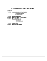
2.1 Connection for standard use
■
To use the TU series, external parts should be connected as shown in Fig. 2.1.
■
The TU series should be conduction-cooled. Use a heatsink or fan to dissipate heat.
Fig. 2.1
Connection for
standard use
Table 2.1
Parts name
・Parts name are shown in Table 2.1 as reference.
・External parts should be changed according to the ambient temperature, and
input and output conditions.
For details, refer to the selection method of individual parts.
A
-2
AC1
AC2
+VOUT
-VOUT
-BCFG
C11
F11 TH11
CY1
+BC
Cbc C20
+
Co
+
Load
C40
Noise
Filter
AC
INPUT
+S
-S
L11 L12
CY2
CY3
CX1 CX2
SK11
SK21,22
SA11
2. Connection for Standard Use
Heatsink
+S,-S:TUNS100
Applications Manual
TUNS50/100
Rating Part name Rating Part name
1F11 250V/2A SBL20
(Daito Communication Apparatus )
250V/3.15A SBL32
(Daito Communication Apparatus )
2C11 AC310V/1uF LE105-MX
(OKAYA ELECTRIC INDUSTRIES )
AC310V/1uF LE105-MX
(OKAYA ELECTRIC INDUSTRIES )
3CY1
AC250V/2200pF
CD45-E2GA222M
(TDK)
AC250V/2200pF
CD45-E2GA222M
(TDK)
4L11 9.3mH/1A SS11VL-R10093
(TOKIN )4.3mH/1.7A SSB11V-R17043
(TOKIN )
5L12 9.3mH/1A SS11VL-R10093
(TOKIN )4.3mH/1.7A SSB11V-R17043
(TOKIN )
6CX1
AC310V/0.22uF
LE224-MX
(OKAYA ELECTRIC INDUSTRIES )
AC310V/0.68uF
LE684-MX
(OKAYA ELECTRIC INDUSTRIES )
7CX2
AC310V/0.22uF
LE224-MX
(OKAYA ELECTRIC INDUSTRIES )
AC310V/0.68uF
LE684-MX
(OKAYA ELECTRIC INDUSTRIES )
8CY2
AC250V/2200pF
CD45-E2GA222M
(TDK)
AC250V/2200pF
CD45-E2GA222M
(TDK)
9CY3 ----
F05
DC10V/2200uF
ELXZ100ELL222MK20S
(Ni
pp
on Chemi-Con)
DC10V/2200uF
ELXZ100ELL222MK20S
(Ni
pp
on Chemi-Con)
F12
DC25V/470uF
ELXZ250ELL471MJ16S
(Ni
pp
on Chemi-Con)
DC25V/470uF
ELXZ250ELL471MJ16S
(Ni
pp
on Chemi-Con)
F24
DC35V/220uF
ELXZ350ELL221MJC5S
(Ni
pp
on Chemi-Con)
DC35V/220uF
ELXZ350ELL221MJC5S
(Ni
pp
on Chemi-Con)
11 C40 DC50V/10uF C3216X7R1H106KT
(TDK) DC50V/10uF C3216X7R1H106KT
(TDK)
12 Cbc
DC420V/82u
F
EKXJ421ELL820MLP1S
(Ni
pp
on Chemi-Con)
DC420V/120u
F
EKXJ421ELL121MM40S
(Ni
pp
on Chemi-Con)
13 C20
DC450V/0.47uF
ECW-F2W474JA
(Panasonic Electronic Components)
DC450V/0.47uF
ECW-F2W474JA
(Panasonic Electronic Components)
14 TH11 5Ω5D2-08LC
(SEMITEC)8Ω8D2-11LC
(SEMITEC)
15
SK11
SK21
SK22
620V TND14V-621
(Nippon Chemi-Con )
620V TND14V-621
(Nippon Chemi-Con )
16 SA11 3kV DSA-302MA
(Mitsubishi Materials)3kV DSA-302MA
(Mitsubishi Materials)
10 Co Output capacitor
Bypass capacitor
Capacitor for boost
voltage
Inrush current
limiting resistor
Varistor
Surge absorber
Noise
filter
Line Filter
X capacitor
Y capacitor
Smoothing capacitor
for boost voltage
TUNS50 TUNS100
Input fuse
Input capacitor
Y capacitor
No. Symbol Item

2.2 Input fuse: F11
■
No protective fuse is preinstalled on the input side. To protect the unit, install a slow-blow
type fuse shown in Table 2.2 in the input circuit.
Table 2.2
Recommended
fuse
2.3 Input capacitor: C11
■
Connect a film capacitor of 1 uF or higher as input capacitor C11.
■
Use a capacitor with a rated voltage of AC250V which complies with the safety standards.
■
If C11 is not connected, the power supply or external components may be damaged.
■
Ripple current values flowing into C11 as listed in Table 2.1 are shown in Fig. 2.2.
■
The frequency of the ripple current is 80 kHz to 600 kHz.
■
When selecting a capacitor, check the maximum allowable ripple current.
■
The ripple current changes with PCB patterns, external parts, ambient temperature, etc.
Check the actual ripple current value flowing through C11.
Fig. 2.2
Ripple current
values
C11
Model TUNS50 TUNS100
A-3
Rated current 2A 3.15A
0
250
500
750
1000
0 20 40 60 80 100 120
Output currrent[%]
Ripple Current[mA]
TUNS50(100VAC)
TUNS50(200VAC)
TUNS100(100VAC)
TUNS100(200VAC)
Applications Manual
TUNS50/100

2.4 Y Capacitors and noise filters: CY, CX, L1
■
The TU series have no internal noise filter.
Connect external noise filters and capacitors (CY) to reduce conduction noise and stabilize
the operation of the power supply.
■
Noise filters should be properly designed when the unit must conform to the EMI/EMS
standards or when surge voltage may be applied to the unit.
■
Install the primary Y capacitor (CY1) as close as possible to the input pins (within 50 mm
from the pins).
A capacitance of 470 pF or more is required.
■
When the total capacitance of CYs exceeds 8,800 pF, input-output withstanding voltage
may be dropped. In this case, either reduce the capacitance of Y capacitors or install a
grounding capacitor between output and FG.
■
Use capacitors with a rated voltage of AC250V which comply with the safety standards
as CY.
2.5 Output capacitors: Co, C40
■
Install an external capacitor, Co, between +VOUT and -VOUT pins for stable operation
of the power supply. Recommended capacitance of Co is shown in Table 2.3.
■
Use low impedance electrolytic capacitors with excellent temperature characteristics.
■
When used at ambient temperatures below 0 ºC, the output ripple voltage increases due
to the characteristics of equivalent series resistance (ESR). In this case, connect three
capacitors, Co, of recommended capacitance in parallel connection.
■
Specifications, output ripple and ripple noise as evaluation data values are measured
according to Fig. 2.3.
Table 2.3
Recommended
capacitance
Co
Fig. 2.3
Measuring
environment
Output Voltage
TUNS50 TUNS100
12V 470uF 470uF
5V 2,200uF 2,200uF
A-4
24V 220uF 220uF
Applications Manual
TUNS50/100

2.6 Smoothing capacitor for boost voltage: Cbc
■
To smooth boost voltage, connect Cbc across +BC and -BC.
Recommended capacitance of Cbc is shown in Table 2.4.
■
Install a capacitor Cbc whose rated voltage is DC420 V or higher within the allowable
capacitance.
■
When operated below 0ºC, operation may become unstable as boost ripple voltage
increases due to ESR characteristics. Choose a capacitor which has higher capacitance
than recommended.
Select a capacitor so that the ripple voltage of the boost voltage is 30 Vp-p or below.
■
If the ripple voltage of the boost voltage increases, the ripple current rating of the
smoothing capacitor may be exceeded. Check the maximum allowable ripple current of
the capacitor.
■
The ripple current changes with PCB patterns, external parts, ambient temperature, etc.
Check the actual ripple current value flowing through Cbc.
Table 2.4
Recommended
capacitance
Cbc
2.7
Capacitor for boost voltage :C20
■
Install a film capacitor with a rating of 0.47uF/DC450V or higher as C20.
■
If C20 is not connected, the power supply or external components may be damaged.
■
Ripple current values flowing into C20 as listed in Table 2.1 are shown in Fig. 2.4.
■
The frequency of the ripple current is 80 kHz to 600 kHz.
■
The ripple current flows into this capacitor. Check the maximum allowable ripple
current of the capacitor when selecting.
■
The ripple current changes with PCB patterns, external parts, ambient temperature, etc.
Check the actual ripple current value flowing through C20.
Fig. 2.4
Ripple current
values
C20
A-5
Model Recommended capacitance Allowable capacitance range
TUNS50 82uF 47uF ~ 150uF
TUNS100 120uF 68uF ~ 220uF
0
100
200
300
400
500
0 20 40 60 80 100 120
Output currrent[%]
Ripple Current[mA]
TUNS50(100VAC)
TUNS50(200VAC)
TUNS100(100VAC)
TUNS100(200VAC)
Applications Manual
TUNS50/100

2.8 Inrush current limiting thermistor: TH11
■
The TU series have no internal inrush current limiting circuit.
■
Inrush current may possibly damage internal components. Provide a power thermistor
or inrush current limiting circuit in the input line to keep inrush current below 60A.
The characteristics of power thermistor as listed in Table 2.1 are shown in Fig. 2.5.
■
When using a power thermistor and turning it ON/OFF repeatedly within a short period
of time, keep appropriate intervals to allow the power supply to cool down sufficiently
before turning on. Such intervals are also required when an inrush current limiting
circuit is used.
■
Inrush current values with external parts as listed in Table 2.1 are shown in Fig. 2.6.
■
The inrush current changes by PCB pattern, parts characteristic etc.
Check the actual inrush current value flowing through the AC line.
Fig. 2.5
Characteristics of
power thermistor
TH11
Fig. 2.6
Inrush current
values
■
Under low temperature conditions, the output of power supply may be unstable due
to high ESR values of the power thermistor and Cbc. Check with the actual device
before use.
※
Refer to page A-8 for operation under low temperature conditions.
A-6
AC200Vin
Ta:70ºC
Ta:25ºC
Ta:-10ºC 11A
22A
36A
TUNS50F24
8D2-11L
5D2-08L
Applications Manual
TUNS50/100

3.1 Input voltage derating
■
The Input voltage derating curve is shown in Fig. 3.1.
Fig. 3.1
Input voltage
derating
3.2 Output current derating
■
The TU series should be conduction-cooled.
■
Fig. 3.2 shows the derating curve in relation with the temperature of the aluminum
base plate.
Note that operation within the shaded area will cause a significant level of ripple and
ripple noise.
■
Measure the temperature of the aluminum base plate at the center.
■
Attention should be paid to thermal fatigue life due to temperature fluctuations by
self-heating. Make the range of temperature fluctuations as narrow as possible if
temperature often fluctuates.
Fig. 3.2
Output current
derating
A-7
2.1
Pin configuration
3. Derating
Applications Manual
TUNS50/100

4.1 Outline of low temperature operation
■
At low temperatures, output may become unstable immediately after startup or at
dynamic load changes due to high ESR values of the power thermistor and Cbc.
Check with the actual device before use.
■
Operation becomes stable as the temperature of the power thermistor rises.
■
To prevent such unstable operation, choose a low ESR capacitor as Cbc, that has
sufficient capacitance within the allowable range and excellent temperature
characteristics.
<Notes for operation at ambient temperatures between -10ºC and -40ºC>
* Avoid the gradual increase of input voltage and forced air cooling.
* Output voltage may remain unstable at low load current. In this case, use the
minimum load current.
* One minute after startup, the characteristics of TH11 and Cbc become stable,
which then stabilizes output.
■
Fig. 4.1 shows stable operation at 25ºC and unstable operation at -40ºC after startup
and at dynamic load changes.
Fig.4.1
Difference of
operation with
temperature
A-8
2.1
Pin configuration
4. Operation Under Low Temperature Conditions
Startup (TUNS100)
Load 0% to 100%(TUNS100)
Vac
(100V/div)
Vin
(100V/div)
Vo
(2V/div) (200ms/div)
Vac
(100V/div)
Vin
(100V/div)
Vo
(2V/div)
unstable
(200ms/div)
Io
(10A/div)
Vo
(2V/div) (100ms/div)
Io
(10A/div)
Vo
(2V/div)
unstable
(100ms/div)
Vac Vin Vo
Io
Applications Manual
TUNS50/100

4.2 Improvement of unstable operation
■
Unstable operation can be improved by increasing the capacitance of Cbc.
At low temperatures, increase the capacitance of Cbc within the range of recommended
values.
■
Fig. 4.2 shows the boundary line examples of stable and unstable operation.
Fig. 4.2
Boundary line
of stable and
unstable operation
4.3 Relationship between unstable operation and input voltage
■
When the input voltage is low, the area for unstable operation is extended.
■
Fig. 4.3 shows differences in operation with input voltage.
Fig. 4.3
Difference in
operation with
Vin
■
Page A-11 shows boundary line examples between stable and unstable operation.
(Data were obtained from circuit connection shown in Fig. 2.1 with external parts
shown in Table 2.1.)
A-9
0
20
40
60
80
100
120
-50 -40 -30 -20 -10 0
Temperature[ºC]
Load [%]
68uF
120uF
220uF
Stable
Unstable or out of operation
0
20
40
60
80
100
120
-50 -40 -30 -20 -10 0
Temperature[ºC]
Load [%]
68uF
120uF
220uF
Stable
Unstable or out of operation
Startup (TUNS100) Load 0% to 100%(TUNS100)
Startup (TUNS100)
AC90Vin AC85Vin
Vac
(100V/div)
Vin
(100V/div)
Vo
(2V/div) (200ms/div)
Vac
(100V/div)
Vin
(100V/div)
Vo
(2V/div) (200ms/div)
Applications Manual
TUNS50/100

■
Holdup time is determined by the capacitance of Cbc. Fig. 5.1 shows the relationship
between holdup time and load within the allowable capacitance of Cbc.
Fig. 5.1
Relationship
between
holdup time
and Cbc
A-10
10
100
1000
0 20 40 60 80 100 120
Load[%]
Holdup time[ms]
min:47uF
typ:82uF
max:150uF
10
100
1000
0 20 40 60 80 100 120
Load[%]
Holdup time[ms]
min:68uF
typ:120uF
max:220uF
2.1
Pin configuration
5. Holdup Time
TUNS50 TUNS100
Applications Manual
TUNS50/100

Fig. A
Boundary line
examples between
unstable and
stable operation
A-11
0
20
40
60
80
100
120
-50 -40 -30 -20 -10 0
Temperature[ºC]
Load [%]
47uF
82uF
150uF
Stable
Unstable or out of operation
0
20
40
60
80
100
120
-50 -40 -30 -20 -10 0
Temperature[ºC]
Load [%]
47uF
82uF
150uF
Stable
Unstable or out of operation
0
20
40
60
80
100
120
-50 -40 -30 -20 -10 0
Temperature[ºC]
Load [%]
47uF
82uF
150uF
Stable
Unstable or out of operation
AC85Vin AC90Vin AC170Vin
0
20
40
60
80
100
120
-50 -40 -30 -20 -10 0
Temperature[ºC]
Load [%]
68uF
120uF
220uF
Stable
Unstable or out of operation
0
20
40
60
80
100
120
-50 -40 -30 -20 -10 0
Temperature[ºC]
Load [%]
68uF
120uF
220uF
Stable
Unstable or out of operation
0
20
40
60
80
100
120
-50 -40 -30 -20 -10 0
Temperature[ºC]
Load [%]
68uF
120uF
220uF
Stable
Unstable or out of operation
AC85Vin AC90Vin AC170Vin
2.1
Pin configuration
6.Appendix
0
20
40
60
80
100
120
-50 -40 -30 -20 -10 0
Temperature[ºC]
Load [%]
47uF
82uF
150uF
Stable
Unstable or out of operation
0
20
40
60
80
100
120
-50 -40 -30 -20 -10 0
Temperature[ºC]
Load [%]
47uF
82uF
150uF
Stable
Unstable or out of operation
0
20
40
60
80
100
120
-50 -40 -30 -20 -10 0
Temperature[ºC]
Load [%]
47uF
82uF
150uF
Stable
Unstable or out of operation
AC85Vin AC90Vin AC170Vin
Boundary line of stable operation at startup (TUNS50)
Boundary line of stable operation at dynamic load change from 0% to 100% (TUNS50)
Boundary line of stable operation at startup (TUNS100)
Boundary line of stable operation at dynamic load change from 0% to 100% (TUNS100)
Applications Manual
TUNS50/100

■
There are notes for PWB board design at recommended circuit in this applications manual.
See below.
Picture A
Recommended
external
circuit
①
Input Fuse: F11
⑤
Capacitor between +BC/-BC
②
Noise Filter Aluminum Capacitor
: Cbc
Line filter : L11, L12 Film Capacitor : C20
X Capacitor : CX1, CX2
⑥
Y capacitor at BC : CY1
Y Capacitor : CY2, CY3
⑦
Output Capacitor
③
Thermistor : TH11 Aluminum Capacitor
: Co
④
X capacitor between AC IN : C11 Ceramic Capacitor : C40
⑧
FG Terminal (Screw holes of the PS)
A-12
7.Notes for external circuit design
When the fuse is blown out, input voltage would be applied between the terminals of the
fuse F11.
Keep the distance of the pattern between the terminals of the fuse more than 2.5mm if
you must be complied safety approvals.
Noise filter is build by Line filters (L11, L12), X capacitor (CX1, CX2) and Y
capacitor(CY2,Y3). And the Noise filter is used to reduce conduction noise from power
supply.
Off-the-shelf Noise filter is also available.
If the Line filter is placed near the components which is switching at high frequency, the
conduction noise may be increased because the noise goes into the Line filter.
Therefore, the Lline filter should be shielded or keep the distance from the source of
noise.
The effect of noise reduction by Y capacitor depends on the place of the FG connection.
Recommend connecting Y capacitor to the FG terminal of the power supply as short as
possible.
Please evaluate before use.
①Input Fuse : F11
②Noise filter
Applications Manual
TUNS50/100
⑥
⑧
AC1
AC2
+VOUT
-VOUT
-BCFG
C11
F11 TH11
CY1
+BC
Cbc C20
+
Co+Load
C40
Noise
Filter
+S
-S
L11 L12
CY2
CY3
CX1 CX2
① ② ③
④
⑤
⑦
ACIN TUNS50
TUNS100
※Only TUNS100
has +S and -S pin

A-13
③Thermistor : TH11
Connect the FG terminal of the power supply to the PWB by screw.
If the FG terminals of the power supply is not connected properly, malfunction or failure
may happen.
Expose the solder mask around the hole of the FG connection on the PWB to connect FG
terminals by screws.
④X Capacitor between +BC/-BC : C11
⑤Capacitor between BC terminals : Cbc, C20
⑥Y capacitor at +BC/-BC : CY1
⑦Output Capacitor : Co, C40
⑧FG terminals of the power supply
Applications Manual
TUNS50/100
The thermistor may become hot by the condition of the use.
Keep the distance between the thermistor and other components.
Huge ripple current flows into the X capacitor C11.
Place the X capacitor near the power supply as close as possible.
The high voltage(Approx. 380VDC) is applied between +BC and -BC terminals.
The distance between +BC and -BC terminals must be 2.5mm or more.
Huge ripple current flows into the capacitor C20.
Place C20 near the power supply as close as possible.
CY1 should be connected to the FG terminal of the power supply as short as
possible.
Output capacitor should be near the load.
Output voltage may become unstable if the impedance of the output lines are high.
In this case, add Aluminum capacitor near the +Vout/-Vout terminals.
When the output ripple and ripple noise must be reduced, ceramic capacitor C40
which has good characteristic at high frequency should be used.
If through-hole type ceramic capacitor is used, the effect of the noise reduction
would be reduced by the impedance of the lead frame of the components.
Please evaluate before use.

Picture B
Example of
the pattern
layout
A-14
AC(N)
AC(L)
(Back of Fuse)
AC(L))
(In front of Fuse)
+BC
GND(-BC)
Fig B.3 Pattern overlay
Fig B.1 Example of the pattern and
components layout (Top layer)
Fig B.2 Example of the pattern and
components layout (Bottom layer)
Fig B.4 Example of TUNS50F TEST BOARD
FG
Secondary
Circuit
8.0mm
or
more
5.0mm
or
more
1.6mm
or more
Minimum
clearance and
creepage for
applying safety
approval (60950-1)
Applications Manual
TUNS50/100
F11
L11
L12
CX1
CX2
CY2
CY1
Cbc Cbc
C11
TH11
Co
Co
Co
C20
TUNS50F
C40
ACIN
DCOUT
/