
RICAMBI ORIGINALI
ORIGINAL SPARE PARTS
PIECES DE RECHANGE ORIGINALES
ORIGINALERSATZTEILE
REPUESTOS ORIGINALES
ORIGINEEL ONDERDEEL
SCHEDA ELETTRONICA
CONTROL BOARD
CARTE ELECTRONIQUE
STEUER PLATINE
TARJETA ELECTRONICA
ELEKTRONISCHE PRINTKAART
Nederlands NL
Español ES
Deutch DE
Français FR
English EN
Italiano IT
ZL180
Page is loading ...
Page is loading ...
Page is loading ...
Page is loading ...
Page is loading ...
Page is loading ...
Page is loading ...

The data and information reported in this installation manual are susceptible to change at any time and without obligation on CAME cancelli automatici s.p.a. to notify users.
Pag.
9
- Manual code:
319
319
LR0
LR0
8
ver.
1.0
1.0 11/2007 © CAME cancelli automatici s.p.a.
ENGLISH
EN
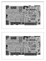
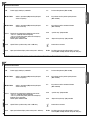
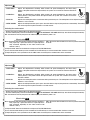
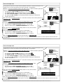
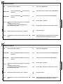
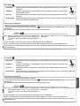
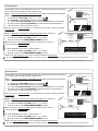
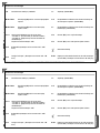
Electrical connections
Connection of antenna
“Open during closing” (N.C.) socket
10-11
2-7
2-C3
1-2
2-C1
Pulsante Stop button (N.C. socket)
Key selector and/or commands button
(N.O. contact)
Terminals for powering the following accessories:
- 24V a.c. (normally alternated power)
- 24V a.c. (continuous power) when the emergency
batteries are in operation.
Overall power allowed: 34W
“partial stop” (N.C.) socket
10-E
L-N
Signal Flasher (socket rating: 24V - 25W max.)
B1-B2
Possible output of the radio receiver’s second
channel (N.O. socket). Socket rating: 5A-24V (d.c.).
Power supply 230V (a.c.) 50/60 Hz
10-5
Open gate indicator-light (socket rating: 24V - 3W max.).
2-3P
Key selector and/or partial opening button
(N.O. socket)
M1-N1-RALL1
M2-N2-RALL2
24V d.c. gearmotor (
M2)
featuring delayed
action on closing
24V d.c. gearmotor (
M1)
featuring delayed
action on opening
The data and information reported in this installation manual are susceptible to change at any time and without obligation on CAME cancelli automatici s.p.a. to notify users.
Pag.
9
- Manual code:
319
319
LR0
LR0
8
ver.
1.0
1.0 11/2007 © CAME cancelli automatici s.p.a.
ENGLISH
EN
Electrical connections
Connection of antenna
“Open during closing” (N.C.) socket
10-11
2-7
2-C3
1-2
2-C1
Pulsante Stop button (N.C. socket)
Key selector and/or commands button
(N.O. contact)
Terminals for powering the following accessories:
- 24V a.c. (normally alternated power)
- 24V a.c. (continuous power) when the emergency
batteries are in operation.
Overall power allowed: 34W
“partial stop” (N.C.) socket
10-E
L-N
Signal Flasher (socket rating: 24V - 25W max.)
B1-B2
Possible output of the radio receiver’s second
channel (N.O. socket). Socket rating: 5A-24V (d.c.).
Power supply 230V (a.c.) 50/60 Hz
10-5
Open gate indicator-light (socket rating: 24V - 3W max.).
2-3P
Key selector and/or partial opening button
(N.O. socket)
M1-N1-RALL1
M2-N2-RALL2
24V d.c. gearmotor (
M2)
featuring delayed
action on closing
24V d.c. gearmotor (
M1)
featuring delayed
action on opening

The data and information reported in this installation manual are susceptible to change at any time and without obligation on CAME cancelli automatici s.p.a. to notify users.
Pag.
10
10 - Manual code:
319
319
LR0
LR0
8
ver.
1.0
1.0 11/2007 © CAME cancelli automatici s.p.a.
ENGLISH
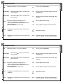
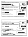
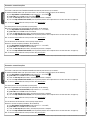
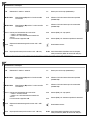
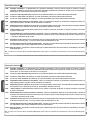
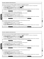
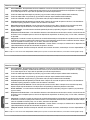
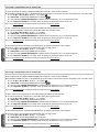
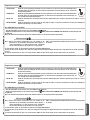
The ZL180 is calibrated to the F7024N or A3024N commands for gate leaves of up to 3 meters.
To command A5024N models (with gate leaves of over 3 m ) and reduce peripheral speed, do the following:
a) - Set dip switches 1 and 6 to ON (and dip switches 2, 3, 4, 5 to OFF) E;
b) - press CH1: the red PROG led will start to blink B C;
c) - when the led stays on (after about 5 seconds) the procedure is complete;
d) - set to the dip switches back to OFF (or to the previous position, which depends on the functions selection, see page 12).
N.B.: to return to default, follow the same procedure while pressing CH2.
The control panel is set for 2 gearmotors (2 leaved gates).
With only one gearmotor (one-leaved gates; M2 gearmotor), do t
he following:
he following:
a
a
) - Set
) - Set
dip switches 4 and 6 to ON
dip switches 4 and 6 to ON (and dip switches 1, 2, 3, 5 to OFF)
;
;
b) - press CH1: the red PROG led will start to blink;
c) - when the led stays on (after about 5 seconds) the procedure is complete;
d) - set to the dip switches back to OFF (or to the previous position, which depends on the functions selection, see page 12).
N.B.: to return to default, follow the same procedure while pressing CH2.
Gearmotors connection options
The microswitches on RA terminals, set the opening stop by default.
However, to activate the opening slowdown, do the following:
a) - Set dip switches 5 and 6 to ON (and dip switches 1, 2, 3, 4 to OFF)
;
;
b) - press CH2: the red PROG led will start to blink;
c) - when the led stays on (after about 5 seconds) the procedure is complete;
d) - set to the dip switches back to OFF (or to the previous position, which depends on the functions selection, see page 12).
N.B.: to return to default, follow the same procedure while pressing CH1.
The data and information reported in this installation manual are susceptible to change at any time and without obligation on CAME cancelli automatici s.p.a. to notify users.
Pag.
10
10 - Manual code:
319
319
LR0
LR0
8
ver.
1.0
1.0 11/2007 © CAME cancelli automatici s.p.a.
ENGLISH
The ZL180 is calibrated to the F7024N or A3024N commands for gate leaves of up to 3 meters.
To command A5024N models (with gate leaves of over 3 m ) and reduce peripheral speed, do the following:
a) - Set dip switches 1 and 6 to ON (and dip switches 2, 3, 4, 5 to OFF) E;
b) - press CH1: the red PROG led will start to blink B C;
c) - when the led stays on (after about 5 seconds) the procedure is complete;
d) - set to the dip switches back to OFF (or to the previous position, which depends on the functions selection, see page 12).
N.B.: to return to default, follow the same procedure while pressing CH2.
The control panel is set for 2 gearmotors (2 leaved gates).
With only one gearmotor (one-leaved gates; M2 gearmotor), do t
he following:
he following:
a
a
) - Set
) - Set
dip switches 4 and 6 to ON
dip switches 4 and 6 to ON (and dip switches 1, 2, 3, 5 to OFF)
;
;
b) - press CH1: the red PROG led will start to blink;
c) - when the led stays on (after about 5 seconds) the procedure is complete;
d) - set to the dip switches back to OFF (or to the previous position, which depends on the functions selection, see page 12).
N.B.: to return to default, follow the same procedure while pressing CH2.
Gearmotors connection options
The microswitches on RA terminals, set the opening stop by default.
However, to activate the opening slowdown, do the following:
a) - Set dip switches 5 and 6 to ON (and dip switches 1, 2, 3, 4 to OFF)
;
;
b) - press CH2: the red PROG led will start to blink;
c) - when the led stays on (after about 5 seconds) the procedure is complete;
d) - set to the dip switches back to OFF (or to the previous position, which depends on the functions selection, see page 12).
N.B.: to return to default, follow the same procedure while pressing CH1.

The data and information reported in this installation manual are susceptible to change at any time and without obligation on CAME cancelli automatici s.p.a. to notify users.
Pag.
11
11 - Manual code:
319
319
LR0
LR0
8
ver.
1.0
1.0 11/2007 © CAME cancelli automatici s.p.a.
ENGLISH
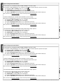
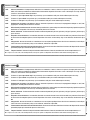
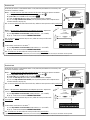
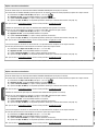
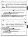
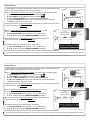
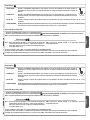
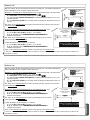
Mode 1 – Excludes use of the 2nd radio channel on B1-B2; after connecting it, operate as follows:
a) - Set dip switch 6 to ON (and dip switches 1, 2, 3, 4, 5 to OFF) E
;
;
b) - press CH1: the red PROG led will start to blink B C;
c) - when the led stays on (after about 5 seconds) the procedure is complete;
d) - set to the dip switches back to OFF (or to the previous position, which depends on the
functions selection, see page 12).
N.B.: to return to default (2nd radio channel on B1-B2), follow the same procedure while pressing CH2.
ZL180 lets you connect, in two different modes, a 12V (15W max) electrolock and, if necessary, also
activate the “Ram Blow” function.
Modo 2 - Non permette il collegamento di una lampada spia su 10-5; dopo averla
connessa:
a
a
) - Set
) - Set
dip switches 2 and 6 to ON
dip switches 2 and 6 to ON (and dip switches 1, 3, 4, 5 to OFF)
;
;
b
b
),
),
c
c
),
),
d
d
) - continue with the above
) - continue with the above
COMMON PROCEDUR
COMMON PROCEDURE.
N.B.: to return to default (indicator lamp on 10-5), follow the same procedure while
pressing CH2.
10 B1
B2
RALL1
transformer
terminal
5
place
a 3.15 A
fuse in between
RALL1
transformer
terminal
In both modes, to activate the “ram blow” (1):
a
a
) - Set
) - Set
dip switches 3 and 6 to ON
dip switches 3 and 6 to ON (and dip switches 1, 2, 4, 5 to OFF)
;
;
b
b
),
),
c
c
),
),
d
d
) - continue with the above
) - continue with the above
COMMON PROCEDUR
COMMON PROCEDURE.
N.B.: to exclude the ram blow, follow the same procedure while pressing CH2.
(1) Upon each opening command, the gate leaves press on the closing jamb for one second, assisting the electrolock release operation.
Mode 1
Mode 2
Electrical lock
The data and information reported in this installation manual are susceptible to change at any time and without obligation on CAME cancelli automatici s.p.a. to notify users.
Pag.
11
11 - Manual code:
319
319
LR0
LR0
8
ver.
1.0
1.0 11/2007 © CAME cancelli automatici s.p.a.
ENGLISH
Mode 1 – Excludes use of the 2nd radio channel on B1-B2; after connecting it, operate as follows:
a) - Set dip switch 6 to ON (and dip switches 1, 2, 3, 4, 5 to OFF) E
;
;
b) - press CH1: the red PROG led will start to blink B C;
c) - when the led stays on (after about 5 seconds) the procedure is complete;
d) - set to the dip switches back to OFF (or to the previous position, which depends on the
functions selection, see page 12).
N.B.: to return to default (2nd radio channel on B1-B2), follow the same procedure while pressing CH2.
ZL180 lets you connect, in two different modes, a 12V (15W max) electrolock and, if necessary, also
activate the “Ram Blow” function.
Modo 2 - Non permette il collegamento di una lampada spia su 10-5; dopo averla
connessa:
a
a
) - Set
) - Set
dip switches 2 and 6 to ON
dip switches 2 and 6 to ON (and dip switches 1, 3, 4, 5 to OFF)
;
;
b
b
),
),
c
c
),
),
d
d
) - continue with the above
) - continue with the above
COMMON PROCEDUR
COMMON PROCEDURE.
N.B.: to return to default (indicator lamp on 10-5), follow the same procedure while
pressing CH2.
10 B1
B2
RALL1
transformer
terminal
5
place
a 3.15 A
fuse in between
RALL1
transformer
terminal
In both modes, to activate the “ram blow” (1):
a
a
) - Set
) - Set
dip switches 3 and 6 to ON
dip switches 3 and 6 to ON (and dip switches 1, 2, 4, 5 to OFF)
;
;
b
b
),
),
c
c
),
),
d
d
) - continue with the above
) - continue with the above
COMMON PROCEDUR
COMMON PROCEDURE.
N.B.: to exclude the ram blow, follow the same procedure while pressing CH2.
(1) Upon each opening command, the gate leaves press on the closing jamb for one second, assisting the electrolock release operation.
Mode 1
Mode 2
Electrical lock

The data and information reported in this installation manual are susceptible to change at any time and without obligation on CAME cancelli automatici s.p.a. to notify users.
Pag.
12
12 - Manual code:
319
319
LR0
LR0
8
ver.
1.0
1.0 11/2007 © CAME cancelli automatici s.p.a.
ENGLISH
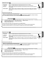
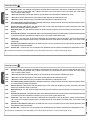
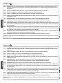
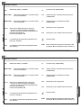
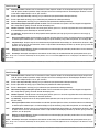
Selecting functions E
1 ON - Automatic closing - the automatic closing timer is activated when on opening the gate leaf has reached the full open stroke.
The time is preset and adjustable, and is subject to the action of any safety devices. It does not activate after a total safety
“stop” or during a power outage;
2 ON - “Open-stop-close-stop” function with button [2-7] and remote control (with built-in radiofrequency card);
2 OFF - “Open-close” function with button [2-7] and remote control (with built-in radiofrequency card);
3 ON - “Open only” function with button [2-7] and remote control (with built-in radiofrequency card);
4 ON - Pre-Flashing during opening and closing - Following an opening or closing command, the flasher connected to [10-E], flashes
for 5 seconds before initiating the operation;
5 ON - Obstacle detection - When motor is idle (gate closed, open or after a total stop command), it prevents any motion if the safety
devices (e.g. photocells) detect any obstacle;
6 ON - Maintained action - the gate works by keeping the button pressed (one button [2-3P] for opening, and one button [2-7] for
closing);
7 OFF - Reopening during closing - if the photocells detect an obstacle during gate closing, the gate motion is inverted until total opening
is reached; connect the safety device to terminals [2-C1); sif not used, set DIP switch to ON;
8 OFF - Partial stop – stops gate when an obstacle is detected by the safety devices; once the obstacle is cleared, the gate remains
still or closes if the automatic closing function is enabled. Connect the safety devices to terminal [2-C3); sif not used, set DIP
switch to ON.
9 ON - Operation of the photocells safety test - this allows the card to assess the efficiency of the safety devices (photocells) after
each opening and closing command;
10 ON - Reaction time – Increases to 2” the running time of the movement inversion function, controlled by the amperometric sensor.
NB – Dip switches 1 through 6 are used, independently, also for the gearmotor and electroloc connection options (pages 10-11).
The data and information reported in this installation manual are susceptible to change at any time and without obligation on CAME cancelli automatici s.p.a. to notify users.
Pag.
12
12 - Manual code:
319
319
LR0
LR0
8
ver.
1.0
1.0 11/2007 © CAME cancelli automatici s.p.a.
ENGLISH
Selecting functions E
1 ON - Automatic closing - the automatic closing timer is activated when on opening the gate leaf has reached the full open stroke.
The time is preset and adjustable, and is subject to the action of any safety devices. It does not activate after a total safety
“stop” or during a power outage;
2 ON - “Open-stop-close-stop” function with button [2-7] and remote control (with built-in radiofrequency card);
2 OFF - “Open-close” function with button [2-7] and remote control (with built-in radiofrequency card);
3 ON - “Open only” function with button [2-7] and remote control (with built-in radiofrequency card);
4 ON - Pre-Flashing during opening and closing - Following an opening or closing command, the flasher connected to [10-E], flashes
for 5 seconds before initiating the operation;
5 ON - Obstacle detection - When motor is idle (gate closed, open or after a total stop command), it prevents any motion if the safety
devices (e.g. photocells) detect any obstacle;
6 ON - Maintained action - the gate works by keeping the button pressed (one button [2-3P] for opening, and one button [2-7] for
closing);
7 OFF - Reopening during closing - if the photocells detect an obstacle during gate closing, the gate motion is inverted until total opening
is reached; connect the safety device to terminals [2-C1); sif not used, set DIP switch to ON;
8 OFF - Partial stop – stops gate when an obstacle is detected by the safety devices; once the obstacle is cleared, the gate remains
still or closes if the automatic closing function is enabled. Connect the safety devices to terminal [2-C3); sif not used, set DIP
switch to ON.
9 ON - Operation of the photocells safety test - this allows the card to assess the efficiency of the safety devices (photocells) after
each opening and closing command;
10 ON - Reaction time – Increases to 2” the running time of the movement inversion function, controlled by the amperometric sensor.
NB – Dip switches 1 through 6 are used, independently, also for the gearmotor and electroloc connection options (pages 10-11).

The data and information reported in this installation manual are susceptible to change at any time and without obligation on CAME cancelli automatici s.p.a. to notify users.
Pag.
13
13 - Manual code:
319
319
LR0
LR0
8
ver.
1.0
1.0 11/2007 © CAME cancelli automatici s.p.a.
ENGLISH
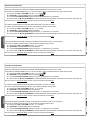
Adjustment A
Activating the remote control
- Connect the antenna’s RG58 cable to the apposite terminals.
- Lock the radiofrequency card into the electronic card D AFTER CUTTING OFF THE POWER SUPPLY (or after disconnecting the batteries).
N.B.: the electronic card only recognises the radiofrequency card when the power is on.
1) Keep the “CH1” button on the electronic card pressed. The LED PROG fl ashes.
2) Press the transmitter button you wish to memorise. The LED will stay on to show memorisation has been successful.
3) Repeat the points 1 and 2 procedures for the “CH2” button associating this to another button on the transmitter.
CH1 = Channel for direct command to a function of the the gearmotor’s
card, (“open only / “open-close-invert” or “open-stop-close-
stop” command, depending on the choice made on DIP
switches 2 and 3).
Memorisation
B C
- «SPEED SENS.» Adjusts the amperometric sensitivity which controls the power developed by the motor during
motion; if the power exceeds the adjusted level, the system sets in motion to invert the direction of
motion.
- «SLOW.SENS.» Adjusts the amperometric sensitivity which controls the power developed by the motor during
slowing downs; if the power exceeds the adjusted level, the system sets in motion to invert the
direction of motion.
- «DELAY 2M» Adjustes the waiting time of the second motor during each closing run. The waiting time can be adjusted anywhere
between 1 and 17 seconds.
- «AUTOM. CLOSING» Adjusts the waiting time when gate is open. Once this time has elapsed, the gate closes automatically. The waiting
time can be adjusted anywhere between 1 and 150 seconds.
CH2 = Channel for direct command an accessory device connected
to B1-B2.
The data and information reported in this installation manual are susceptible to change at any time and without obligation on CAME cancelli automatici s.p.a. to notify users.
Pag.
13
13 - Manual code:
319
319
LR0
LR0
8
ver.
1.0
1.0 11/2007 © CAME cancelli automatici s.p.a.
ENGLISH
Adjustment A
Activating the remote control
- Connect the antenna’s RG58 cable to the apposite terminals.
- Lock the radiofrequency card into the electronic card D AFTER CUTTING OFF THE POWER SUPPLY (or after disconnecting the batteries).
N.B.: the electronic card only recognises the radiofrequency card when the power is on.
1) Keep the “CH1” button on the electronic card pressed. The LED PROG fl ashes.
2) Press the transmitter button you wish to memorise. The LED will stay on to show memorisation has been successful.
3) Repeat the points 1 and 2 procedures for the “CH2” button associating this to another button on the transmitter.
CH1 = Channel for direct command to a function of the the gearmotor’s
card, (“open only / “open-close-invert” or “open-stop-close-
stop” command, depending on the choice made on DIP
switches 2 and 3).
Memorisation
B C
- «SPEED SENS.» Adjusts the amperometric sensitivity which controls the power developed by the motor during
motion; if the power exceeds the adjusted level, the system sets in motion to invert the direction of
motion.
- «SLOW.SENS.» Adjusts the amperometric sensitivity which controls the power developed by the motor during
slowing downs; if the power exceeds the adjusted level, the system sets in motion to invert the
direction of motion.
- «DELAY 2M» Adjustes the waiting time of the second motor during each closing run. The waiting time can be adjusted anywhere
between 1 and 17 seconds.
- «AUTOM. CLOSING» Adjusts the waiting time when gate is open. Once this time has elapsed, the gate closes automatically. The waiting
time can be adjusted anywhere between 1 and 150 seconds.
CH2 = Channel for direct command an accessory device connected
to B1-B2.

The data and information reported in this installation manual are susceptible to change at any time and without obligation on CAME cancelli automatici s.p.a. to notify users.
Pag.
14
14 - Manual code:
319
319
LR0
LR0
8
ver.
1.0
1.0 11/2007 © CAME cancelli automatici s.p.a.
ENGLISH
Disposal
This product, including the packaging, is made up of several types of materials that can be recycled.
Investigate the recycling or disposal systems of the product, complying with prevailing local legislation.
Some electronic components may contain polluting substances. Do not litter.
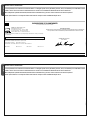
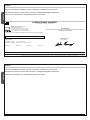
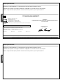
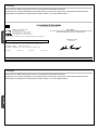
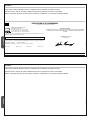
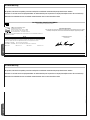
CAME Cancelli Automatici S.p.A.
via Martiri della Libertà, 15
31030 Dosson di Casier - Treviso - ITALY
tel (+39) 0422 4940 - fax (+39) 0422 4941
internet: www.came.it - e-mail: [email protected]
Declares under its own responsibility that the equipments for automatic garage doors and gates listed below:
… comply with the National Law related to the following European Directives and to the applicable parts of the
following Standards.
73/23/EEC - 93/68/EC LOW VOLTAGE DIRECTIVE
89/336/EEC - 92/31/EEC ELECTROMAGNETIC COMPATIBILITY DIRECTIVE
EN 60335-1 EN 61000-6-2 EN 13241-1 EN 61000-6-3
EC DECLARATION OF CONFORMITY
Pursuant to the Low Voltage Directive 73/23/EEC
THE MANAGING DIRECTOR
Andrea Menuzzo
ZL180
Reference code to request a true copy of the original: DDF L EN Z002a
IMPORTANT WARNING!
Do not use the equipment specifi ed here above, before completing the full installation. In full compliance to
the Low Voltage Directive 73/23/EEC
The data and information reported in this installation manual are susceptible to change at any time and without obligation on CAME cancelli automatici s.p.a. to notify users.
Pag.
14
14 - Manual code:
319
319
LR0
LR0
8
ver.
1.0
1.0 11/2007 © CAME cancelli automatici s.p.a.
ENGLISH
Disposal
This product, including the packaging, is made up of several types of materials that can be recycled.
Investigate the recycling or disposal systems of the product, complying with prevailing local legislation.
Some electronic components may contain polluting substances. Do not litter.
CAME Cancelli Automatici S.p.A.
via Martiri della Libertà, 15
31030 Dosson di Casier - Treviso - ITALY
tel (+39) 0422 4940 - fax (+39) 0422 4941
internet: www.came.it - e-mail: [email protected]
Declares under its own responsibility that the equipments for automatic garage doors and gates listed below:
… comply with the National Law related to the following European Directives and to the applicable parts of the
following Standards.
73/23/EEC - 93/68/EC LOW VOLTAGE DIRECTIVE
89/336/EEC - 92/31/EEC ELECTROMAGNETIC COMPATIBILITY DIRECTIVE
EN 60335-1 EN 61000-6-2 EN 13241-1 EN 61000-6-3
EC DECLARATION OF CONFORMITY
Pursuant to the Low Voltage Directive 73/23/EEC
THE MANAGING DIRECTOR
Andrea Menuzzo
ZL180
Reference code to request a true copy of the original: DDF L EN Z002a
IMPORTANT WARNING!
Do not use the equipment specifi ed here above, before completing the full installation. In full compliance to
the Low Voltage Directive 73/23/EEC
Page is loading ...
Page is loading ...
Page is loading ...
Page is loading ...
Page is loading ...
Page is loading ...
Page is loading ...
Page is loading ...
Page is loading ...
Page is loading ...
Page is loading ...
Page is loading ...
Page is loading ...
Page is loading ...
Page is loading ...
Page is loading ...
Page is loading ...
Page is loading ...
Page is loading ...
Page is loading ...
Page is loading ...
Page is loading ...
Page is loading ...
Page is loading ...
Page is loading ...

FRANCE -
CAME France S.a.
CAME France S.a.
7, Rue Des Haras - Z.i. Des Hautes Patures
92737
Nanterre Cedex
Nanterre Cedex
-
- (+33) 1 46 13 05 05 - (+33) 1 46 13 05 00
CAME GmbH Nord
CAME GmbH Nord - DEUTSCHLAND
Akazienstraße, 9
16356
Seefeld
Seefeld - (+49) 33 3988390 _ (+49) 33 39883985
FRANCE -
CAME Automatismes S.a.
CAME Automatismes S.a.
3, Rue Odette Jasse
13015
Marseille -
Marseille - (+33) 4 95 06 33 70 - (+33) 4 91 60 69 05
CAME GmbH Süd
CAME GmbH Süd - DEUTSCHLAND
Kornwestheimer Straße 37
70825
Korntal-
Korntal-Münchingen
- (+49) 71 5037830 _ (+49) 71 50378383
SPAIN -
CAME Automatismos S.a.
CAME Automatismos S.a.
C/juan De Mariana, N. 17-local
28045
Madrid -
Madrid - (+34) 91 52 85 009 - (+34) 91 46 85 442
CAME Americas Automation Llc
CAME Americas Automation Llc - U.S.A
1560 Sawgrass Corporate Pkwy, 4th Floor
Sunrise
Sunrise, FL 33323 - (+1) 305 433 3307 _ (+1) 305 396 3331
SPAIN -
CAME Automatismos Catalunya S.a.
CAME Automatismos Catalunya S.a.
P.i. Moli Dels Frares N. 23 C/a
08620
Sant Vicenc Del Horts
Sant Vicenc Del Horts
-
- (+34) 93 65 67 694 - (+34) 93 67 24 505
CAME Middle East Fzco -
CAME Middle East Fzco - U.A.E.
Po Box 17131 Warehouse N. Be02 - South Zone, Jebel Ali Free Zone
Dubai
Dubai - (+971) 4 8860046 _ (+971) 4 8860048
PORTUGAL -
Paf - CAME
Paf - CAME
Estrada Nacional 249-4 Ao Km 4,35 - Cabra Figa - Trajouce
2635-047
Rio De Mouro -
Rio De Mouro - (+351) 219 257 471 - (+35) 219 257 485
CAME Polska Sp.Zo.o -
CAME Polska Sp.Zo.o - POLAND
Ul. Ordona 1
01-237
Warszawa
Warszawa - (+48) 22 8365076 _ (+48) 22 8363296
UNITED KINGDOM -
CAME United Kingdom Ltd.
CAME United Kingdom Ltd.
Unit 3 Orchard Business Park - Town Street, Sandiacre
Nottingham
Nottingham Ng10 5du - (+44) 115 9210430 - (+44) 115 9210431
S.c. CAME Romania S.r.l. -
S.c. CAME Romania S.r.l. - ROMANIA
B-dul Mihai Eminescu, Nr. 2, Bloc R2 - Scara A, Parter, Ap. 3
Buftea, Judet Ilfov
Bucarest
Bucarest
- (+40) 21 3007344 _ (+40) 21 3007344
BELGIUM -
CAME Belgium Sprl
CAME Belgium Sprl
Zoning Ouest 7
7860
Lessines -
Lessines - (+32) 68 333014 - (+32) 68 338019
CAME Russia
CAME Russia - RUSSIA
Leningradskij Prospekt, Dom 80 - Pod’ezd 3, offi ce 608
125190,
Moskva
Moskva - (+7) 495 937 33 07 _ (+7) 495 937 33 08
ITALIA -
CAME Cancelli Automatici S.p.a.
CAME Cancelli Automatici S.p.a.
Via Martiri Della Libertà, 15
31030
Dosson Di Casier
Dosson Di Casier (TV) - (+39) 0422 4940 _ (+39) 0422 4941
Informazioni Commerciali 800 848095 -
www.came.it
www.came.it
CAME Nord s.r.l.
CAME Nord s.r.l. - ITALIA
Piazza Castello, 16
20093
Cologno Monzese
Cologno Monzese (MI)
- (+39) 02 26708293 _ (+39) 02 25490288
ITALIA -
CAME Service Italia S.r.l.
CAME Service Italia S.r.l.
Via Della Pace, 28
31030
Dosson di Casier
Dosson di Casier (TV)
- (+39) 0422 383532 _ (+39) 0422 490044
Assistenza Tecnica 800 295830
Assistenza Tecnica 800 295830
CAME Sud s.r.l.
CAME Sud s.r.l. - ITALIA
Via F. Imparato, 198 - Cm2 Lotto A/7
80146
Napoli -
Napoli - (+39) 081 7524455 _ (+39) 081 7529109
319LR0
319LR0
8
ver.
1.0
1.0 11/2007 © CAME cancelli automatici s.p.a.
FRANCE -
CAME France S.a.
CAME France S.a.
7, Rue Des Haras - Z.i. Des Hautes Patures
92737
Nanterre Cedex
Nanterre Cedex
-
- (+33) 1 46 13 05 05 - (+33) 1 46 13 05 00
CAME GmbH Nord
CAME GmbH Nord - DEUTSCHLAND
Akazienstraße, 9
16356
Seefeld
Seefeld - (+49) 33 3988390 _ (+49) 33 39883985
FRANCE -
CAME Automatismes S.a.
CAME Automatismes S.a.
3, Rue Odette Jasse
13015
Marseille -
Marseille - (+33) 4 95 06 33 70 - (+33) 4 91 60 69 05
CAME GmbH Süd
CAME GmbH Süd - DEUTSCHLAND
Kornwestheimer Straße 37
70825
Korntal-
Korntal-Münchingen
- (+49) 71 5037830 _ (+49) 71 50378383
SPAIN -
CAME Automatismos S.a.
CAME Automatismos S.a.
C/juan De Mariana, N. 17-local
28045
Madrid -
Madrid - (+34) 91 52 85 009 - (+34) 91 46 85 442
CAME Americas Automation Llc
CAME Americas Automation Llc - U.S.A
1560 Sawgrass Corporate Pkwy, 4th Floor
Sunrise
Sunrise, FL 33323 - (+1) 305 433 3307 _ (+1) 305 396 3331
SPAIN -
CAME Automatismos Catalunya S.a.
CAME Automatismos Catalunya S.a.
P.i. Moli Dels Frares N. 23 C/a
08620
Sant Vicenc Del Horts
Sant Vicenc Del Horts
-
- (+34) 93 65 67 694 - (+34) 93 67 24 505
CAME Middle East Fzco -
CAME Middle East Fzco - U.A.E.
Po Box 17131 Warehouse N. Be02 - South Zone, Jebel Ali Free Zone
Dubai
Dubai - (+971) 4 8860046 _ (+971) 4 8860048
PORTUGAL -
Paf - CAME
Paf - CAME
Estrada Nacional 249-4 Ao Km 4,35 - Cabra Figa - Trajouce
2635-047
Rio De Mouro -
Rio De Mouro - (+351) 219 257 471 - (+35) 219 257 485
CAME Polska Sp.Zo.o -
CAME Polska Sp.Zo.o - POLAND
Ul. Ordona 1
01-237
Warszawa
Warszawa - (+48) 22 8365076 _ (+48) 22 8363296
UNITED KINGDOM -
CAME United Kingdom Ltd.
CAME United Kingdom Ltd.
Unit 3 Orchard Business Park - Town Street, Sandiacre
Nottingham
Nottingham Ng10 5du - (+44) 115 9210430 - (+44) 115 9210431
S.c. CAME Romania S.r.l. -
S.c. CAME Romania S.r.l. - ROMANIA
B-dul Mihai Eminescu, Nr. 2, Bloc R2 - Scara A, Parter, Ap. 3
Buftea, Judet Ilfov
Bucarest
Bucarest
- (+40) 21 3007344 _ (+40) 21 3007344
BELGIUM -
CAME Belgium Sprl
CAME Belgium Sprl
Zoning Ouest 7
7860
Lessines -
Lessines - (+32) 68 333014 - (+32) 68 338019
CAME Russia
CAME Russia - RUSSIA
Leningradskij Prospekt, Dom 80 - Pod’ezd 3, offi ce 608
125190,
Moskva
Moskva - (+7) 495 937 33 07 _ (+7) 495 937 33 08
ITALIA -
CAME Cancelli Automatici S.p.a.
CAME Cancelli Automatici S.p.a.
Via Martiri Della Libertà, 15
31030
Dosson Di Casier
Dosson Di Casier (TV) - (+39) 0422 4940 _ (+39) 0422 4941
Informazioni Commerciali 800 848095 -
www.came.it
www.came.it
CAME Nord s.r.l.
CAME Nord s.r.l. - ITALIA
Piazza Castello, 16
20093
Cologno Monzese
Cologno Monzese (MI)
- (+39) 02 26708293 _ (+39) 02 25490288
ITALIA -
CAME Service Italia S.r.l.
CAME Service Italia S.r.l.
Via Della Pace, 28
31030
Dosson di Casier
Dosson di Casier (TV)
- (+39) 0422 383532 _ (+39) 0422 490044
Assistenza Tecnica 800 295830
Assistenza Tecnica 800 295830
CAME Sud s.r.l.
CAME Sud s.r.l. - ITALIA
Via F. Imparato, 198 - Cm2 Lotto A/7
80146
Napoli -
Napoli - (+39) 081 7524455 _ (+39) 081 7529109
319LR0
319LR0
8
ver.
1.0
1.0 11/2007 © CAME cancelli automatici s.p.a.
-
 1
1
-
 2
2
-
 3
3
-
 4
4
-
 5
5
-
 6
6
-
 7
7
-
 8
8
-
 9
9
-
 10
10
-
 11
11
-
 12
12
-
 13
13
-
 14
14
-
 15
15
-
 16
16
-
 17
17
-
 18
18
-
 19
19
-
 20
20
-
 21
21
-
 22
22
-
 23
23
-
 24
24
-
 25
25
-
 26
26
-
 27
27
-
 28
28
-
 29
29
-
 30
30
-
 31
31
-
 32
32
-
 33
33
-
 34
34
-
 35
35
-
 36
36
-
 37
37
-
 38
38
-
 39
39
-
 40
40


Ask a question and I''ll find the answer in the document
Finding information in a document is now easier with AI
in other languages
- italiano: CAME Z24-Z230
- Deutsch: CAME Z24-Z230
- Nederlands: CAME Z24-Z230
Related papers
-
CAME Z24-Z230 Installation guide
-
CAME BX-243C, BX-243C110 Installation guide
-
-
-
-
-
-
-
-


