GREE GMV-1910WM/G-X User manual
- Category
- Split-system air conditioners
- Type
- User manual
This manual is also suitable for

GMV6 DC Inverter VRF Units
(GC202001-I)
Capacity: 22.4kW~272.0kW
Rated Frequency: 50Hz & 60Hz
Operation Range: Cooling: -5~52°C
Heating: -30~24°C

Gree GMV6 DC Inverter VRF Units Service Manual
Contents
Chapter 1 Product ................................................................................................................ 2
1 Unit List ............................................................................................................................. 2
2 Parameters ....................................................................................................................... 3
3 The Range of Production Working Temperature ............................................................. 10
Chapter 2 Commissioning .................................................................................................. 11
1 Commissioning Process ................................................................................................. 11
2 Safety Requirements ...................................................................................................... 11
3 Unit Commissioning ........................................................................................................ 12
4 Unit Function Settings ..................................................................................................... 41
Chapter 3 Faults ................................................................................................................ 72
1 Error Indication ............................................................................................................... 72
2 Troubleshooting .............................................................................................................. 76
3 Non-fault Type Troubleshooting .................................................................................... 182
Chapter 4 Maintenance.................................................................................................... 183
1 Precautions for Refrigerant Leakage ............................................................................ 183
2 Refrigerant Charging..................................................................................................... 183
3 Refrigerant Charging Method ........................................................................................ 185
4 Inspection of Key Parts ................................................................................................. 188
5 Replacement of Key Unit Parts ..................................................................................... 243
6 Explosive View and Parts List ....................................................................................... 277
Appendixes ...................................................................................................................... 283
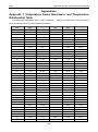
Appendix 1 Temperature Senor Resistance and Temperature Relationship Table ........... 283
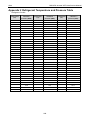
Appendix 2 Refrigerant Temperature and Pressure Table ............................................... 290
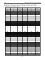
Appendix 3 Pressure Sensor Voltage and Pressure Table ............................................... 291
Appendix 4 Electric Specifications ................................................................................... 294
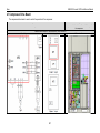
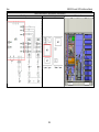
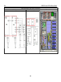
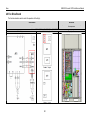
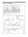
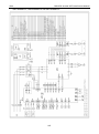
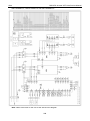
Appendix 5 Circuit Diagram ............................................................................................. 296
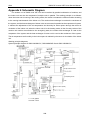
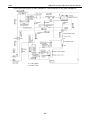
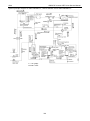
Appendix 6 Schematic Diagram ....................................................................................... 299
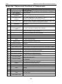
Appendix 7 Names and Functions of Components .......................................................... 302

Gree GMV6 DC Inverter VRF Units Service Manual
1
Preface
Thank you for purchasing GMV6 DC Inverter VRF Units. For correct operation, please read this
manual carefully.
This manual applies to GMV6 series VRF units. It clarifies the safety requirements, basic principles
and implementation methods in engineering commissioning, troubleshooting, and after-sales
maintenance. Relevant professionals must follow the national (local) safety and technical requirements
as well as this manual. Failure to do so may result in improper functioning or damage to the air
conditioning system, or even personal injury.
Safety Instructions
Warning symbols
Symbols in this document indicate different severities and possibilities.
DANGER!
Indicates an imminently hazardous situation which, if not avoided, will result in death or serious injury.
WARNING!
Indicates a potentially hazardous situation which, if not avoided, could result in death or serious injury.
CAUTION!
Indicates a potentially hazardous situation which, if not avoided, may result in minor or moderate
injury. Or indicates an unsafe behavior.
NOTES!
Indicates a situation which could result in equipment or property loss.
INFO
Indicates helpful tips or additional information.
JUMP
Indicates a jump connection.

Gree GMV6 DC Inverter VRF Units Service Manual
2
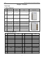
Chapter 1 Product
1 Unit List
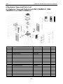
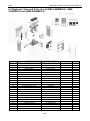
1.1 Basic Modules
HP Product Code Model Power External view
8 CN851W3030 GMV-224WM/G-X 380V-415V 3N~50Hz/60Hz
10 CN851W3010 GMV-280WM/G-X 380V-415V 3N~50Hz/60Hz
12 CN851W2820 GMV-335WM/G-X 380V-415V 3N~50Hz/60Hz
14 CN851W2980 GMV-400WM/G-X 380V-415V 3N~50Hz/60Hz
16 CN851W2990 GMV-450WM/G-X 380V-415V 3N~50Hz/60Hz
18 CN851W2880 GMV-504WM/G-X 380V-415V 3N~50Hz/60Hz
20 CN851W3000 GMV-560WM/G-X 380V-415V 3N~50Hz/60Hz
22 CN851W3020 GMV-615WM/G-X 380V-415V 3N~50Hz/60Hz
24 CN851W2890 GMV-680WM/G-X 380V-415V 3N~50Hz/60Hz
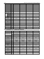
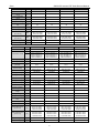
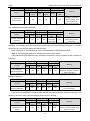
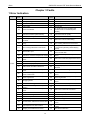
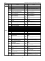
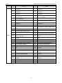
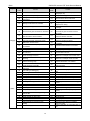
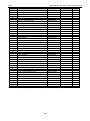
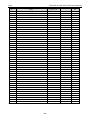
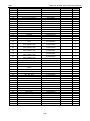
1.2 Combined Modules
HP Standard Combination Model HP Standard Combination Model
16
—
—
58
18+18+22
GMV-1623WM/G-X
18
—
—
60
18+20+22
GMV-1679WM/G-X
20
—
—
62
18+22+22
GMV-1734WM/G-X
22
—
—
64
20+22+22
GMV-1790WM/G-X
24
—
—
66
22+22+22
GMV-1845WM/G-X
26
12+14
GMV-735WM/G-X
68
22+22+24
GMV-1910WM/G-X
28
12+16
GMV-785WM/G-X
70
22+24+24
GMV-1975WM/G-X
30
12+18
GMV-839WM/G-X
72
24+24+24
GMV-2040WM/G-X
32
10+22
GMV-895WM/G-X
74
12+18+22+22
GMV-2069WM/G-X
34
12+22
GMV-950WM/G-X
76
16+18+20+22
GMV-2129WM/G-X
36
14+22
GMV-1015WM/G-X
78
14+20+22+22
GMV-2190WM/G-X
38
18+20
GMV-1064WM/G-X
80
14+22+22+22
GMV-2245WM/G-X
40
18+22
GMV-1119W M/G-X
82
20+20+20+22
GMV-2295WM/G-X
42
20+22
GMV-1175WM/G-X
84
20+20+22+22
GMV-2350WM/G-X
44
22+22
GMV-1230WM/G-X
86
18+22+22+24
GMV-2414WM/G-X
46
22+24
GMV-1295WM/G-X
88
20+22+22+24
GMV-2470WM/G-X
48
24+24
GMV-1360WM/G-X
90
22+22+22+24
GMV-2525WM/G-X
50
12+18+20
GMV-1399WM/G-X
92
22+22+24+24
GMV-2590WM/G-X
52
10+20+22
GMV-1455WM/G-X
94
22+24+24+24
GMV-2655WM/G-X
54
10+22+22
GMV-1510WM/G-X
96
24+24+24+24
GMV-2720WM/G-X
56
12+22+22
GMV-1565WM/G-X
-
-
-

Gree GMV6 DC Inverter VRF Units Service Manual
3
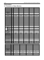
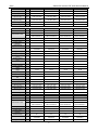
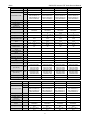
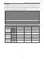
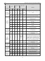
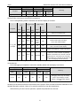
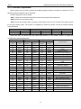
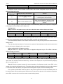
2 Parameters
2.1 Parameters of Basic Modules
Model - GMV-224WM/G-X GMV-280WM/G-X
GMV-335WM/G-X GMV-400WM/G-X GMV-450WM/G-X
HP HP 8 10 12 14 16
Product Code - CN851W3030 CN851W3010 CN851W2820 CN851W2980 CN851W2990
Cooling capacity kW 22.4 28.0 33.5 40.0 45.0
Heating capacity kW 25.0 31.5 37.5 45.0 50.0
Outdoor static
pressure
Pa 0/110 0/110 0/110 0/110 0/110
Noise (sound pressure
level)
dB(A) 56 57 59 59 60
Power -
380V-415V 3N~
50Hz/60Hz
380V-415V 3N~
50Hz/60Hz
380V-415V 3N~
50Hz/60Hz
380V-415V 3N~
50Hz/60Hz
380V-415V 3N~
50Hz/60Hz
Cooling power input kW 5.0 6.2 7.7 9.2 10.8
Heating power input kW 4.8 5.9 7.8 9.5 10.7
Cooling current input A 8.9 11.1 13.8 16.4 19.3
Heating current input A 8.6 10.5 13.9 17.0 19.1
Rated power input kW 12.87 13.15 13.50 18.18 18.74
Rated current A 23 23.5 24.1 32.50 33.5
Compressor type - Inverter scroll Inverter scroll Inverter scroll Inverter scroll Inverter scroll
Compressor function - EVI EVI EVI EVI EVI
Compressor quantity N 1 1 1 1 1
Refrigeration oil No. of
compressor
- FV68H FV68H FV68H FV68H FV68H
Refriger
ation oil
charge
Gross L 4.6 4.6 4.6 6.1 6.1
Compressor
charge
L 1.1 1.1 1.1 1.1 1.1
The others L 3.5 3.5 3.5 5 5
Cooling operation
range
°C -5~52 -5~52 -5~52 -5~52 -5~52
Heating operation
range
°C -30~24 -30~24 -30~24 -30~24 -30~24
Refrigerant type - R410A R410A R410A R410A R410A
Refrigerant charge kg 5.5 5.5 5.7 7 7.5
Maximum drive IDU
NO.
unit 13 16 19 23 26
Gas pipe mm Φ19.05 Φ22.2 Φ25.4 Φ25.4 Φ28.6
Liquid pipe mm Φ9.52 Φ9.52 Φ12.7 Φ12.7 Φ12.7
Outline dimensions
(W × D × H)
mm 930×775×1690 930×775×1690 930×775×1690 1340×775×1690 1340×775×1690
Packing dimensions
(W × D × H)
mm 1000×830×1855 1000×830×1855 1000×830×1855 1400×830×1855 1400×830×1855
Net weight kg 215 215 220 290 290
Gross weight kg 225 225 230 305 305
Model - GMV-504WM/G-X GMV-560WM/G-X GMV-615WM/G-X GMV-680WM/G-X
HP HP 18 20 22 24
Product Code - CN851W2880 CN851W3000 CN851W3020 CN851W2890
Cooling capacity kW 50.4 56 61.5 68
Heating capacity kW 56.5 63 69 76.5
Outdoor static
pressure
Pa 0/110 0/110 0/110 0/110
Noise (sound
pressure level)
dB(A) 61 62 63 64
Power -
380V-415V 3N~
50Hz/60Hz
380V-415V 3N~
50Hz/60Hz
380V-415V 3N~
50Hz/60Hz
380V-415V 3N~
50Hz/60Hz
Cooling power input kW 12.3 13.8 16.2 20.5
Heating power input kW 12.9 13.1 16.9 20.1

Gree GMV6 DC Inverter VRF Units Service Manual
4
Model - GMV-504WM/G-X GMV-560WM/G-X GMV-615WM/G-X GMV-680WM/G-X
Cooling current input A 22.0 24.7 29.0 36.6
Heating current input A 23.1 23.4 30.2 35.9
Rated power input kW 26.30 26.85 27.41 27.41
Rated current A 47 48 49 49
Compressor type - Inverter scroll Inverter scroll Inverter scroll Inverter scroll
Compressor function - EVI EVI EVI EVI
Compressor quantity N 1 2 2 2
Refrigeration oil No.
of compressor
- FV68H FV68H FV68H FV68H
Refrige
ration
oil
charge
Gross L 6.1 7.2 7.2 7.2
Compressor
charge
L 1.1 1.1×2 1.1×2 1.1×2
The others L 5 5 5 5
Cooling operation
range
°C -5~52 -5~52 -5~52 -5~52
Heating operation
range
°C -30~24 -30~24 -30~24 -30~24
Refrigerant type - R410A R410A R410A R410A
Refrigerant charge kg 8 8 8.3 8.3
Maximum drive IDU
NO.
unit 29 33 36 39
Gas pipe mm Φ28.6 Φ28.6 Φ28.6 Φ28.6
Liquid pipe mm Φ15.9 Φ15.9 Φ15.9 Φ15.9
Outline dimensions
(W × D × H)
mm 1340×775×1690 1340×775×1690 1340×775×1690 1340×775×1690
Packing dimensions
(W × D × H)
mm 1400×830×1855 1400×830×1855 1400×830×1855 1400×830×1855
Net weight kg 295 350 350 355
Gross weight kg 310 365 365 370
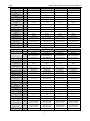
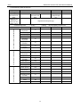
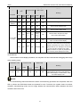
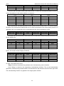
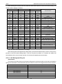
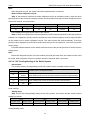
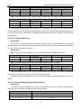
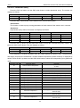
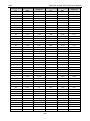
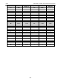
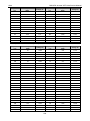
2.2 Parameters of Combined Modules
Model - GMV-735WM/G-X GMV-785WM/G-X GMV-839WM/G-X GMV-895WM/G-X
HP HP 26 28 30 32
Combination mode
- 12+14 12+16 12+18 10+22
-
GMV-335WM/G-X+
GMV-400WM/G-X
GMV-335WM/G-X+
GMV-450WM/G-X
GMV-335WM/G-X+
GMV-504WM/G-X
GMV-280WM/G-X+
GMV-615WM/G-X
Cooling capacity kW 73.5 78.5 83.9 89.5
Heating capacity kW 82.5 87.5 94.0 100.5
Outdoor static
pressure
Pa 0/110 0/110 0/110 0/110
Noise (sound
pressure level)
dB(A) 62 63 64 64
Power -
380V-415V 3N~
50Hz/60Hz
380V-415V 3N~
50Hz/60Hz
380V-415V 3N~
50Hz/60Hz
380V-415V 3N~
50Hz/60Hz
Cooling power input kW 7.7+9.2 7.7+10.8 7.7+12.3 6.2 +16.2
Heating power input kW 7.8+9.5 7.8+10.7 7.8+12.9 5.9+16.9
Cooling current
input
A 13.8+16.4 13.8+19.3 13.8+22.0 11.1+29.0
Heating current
input
A 13.9+17.0 13.9+19.1 13.9+23.1 10.5+30.2
Rated power input kW 13.50+18.18 13.50+18.74 13.50+26.30 13.15+27.41
Rated current A 24.1+32.5 24.1+33.5 24.1+47 23.5+49
Cooling operation
range
°C -5~52 -5~52 -5~52 -5~52
Heating operation
range
°C -30~24 -30~24 -30~24 -30~24
Refrigerant type - R410A R410A R410A R410A
Refrigerant charge kg 5.7+7 5.7+7.5 5.7+8 5.5+8.3
Maximum drive IDU
NO.
unit 43 46 50 53

Gree GMV6 DC Inverter VRF Units Service Manual
5
Model - GMV-735WM/G-X GMV-785WM/G-X GMV-839WM/G-X GMV-895WM/G-X
Gas pipe mm Φ31.8 Φ31.8 Φ31.8 Φ31.8
Liquid pipe mm Φ19.05 Φ19.05 Φ19.05 Φ19.05
Outline dimensions
(W × D × H)
mm
930×775×1690+
1340×775×1690
930×775×1690+
1340×775×1690
930×775×1690+
1340×775×1690
930×775×1690+
1340×775×1690
Packing dimensions
(W × D × H)
mm
1000×830×1855+
1400×830×1855
1000×830×1855+
1400×830×1855
1000×830×1855+
1400×830×1855
1000×830×1855+
1400×830×1855
Net weight kg 220+290 220+290 220+295 215+350
Gross weight kg 230+305 230+305 230+310 225+365
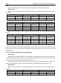
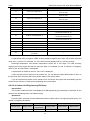
Model - GMV-950WM/G-X GMV-1015WM/G-X GMV-1064WM/G-X GMV-1119W M/ G-X
HP HP 34 36 38 40
Combination mode
- 12+22 14+22 18+20 18+22
-
GMV-335WM/G-X+
GMV-615WM/G-X
GMV-400WM/G-X+
GMV-615WM/G-X
GMV-504WM/G-X+
GMV-560WM/G-X
GMV-504WM/G-X+
GMV-615WM/G-X
Cooling capacity kW 95.0 101.5 106.4 111.9
Heating capacity kW 106.5 114.0 119.5 125.5
Outdoor static
pressure
Pa 0/110 0/110 0/110 0/110
Noise (sound
pressure level)
dB(A) 65 65 65 65
Power -
380V-415V 3N~
50Hz/60Hz
380V-415V 3N~
50Hz/60Hz
380V-415V 3N~
50Hz/60Hz
380V-415V 3N~
50Hz/60Hz
Cooling power input kW 7.7+16.2 9.2+16.2 12.3+13.8 12.3+16.2
Heating power input kW 7.8+16.9 9.5+16.9 12.9+13.1 12.9+16.9
Cooling current
input
A 13.8+29.0 16.4+29.0 22.0+24.7 22.0+29.0
Heating current
input
A 13.9+30.2 17.0+30.2 23.1+23.4 23.1+30.2
Rated power input kW 13.50+27.41 18.18+27.41 26.30+26.85 26.30+27.41
Rated current A 24.1+49 32.5+49 47+48 47+49
Cooling operation
range
°C -5~52 -5~52 -5~52 -5~52
Heating operation
range
°C -30~24 -30~24 -30~24 -30~24
Refrigerant type - R410A R410A R410A R410A
Refrigerant charge kg 5.7+8.3 7+8.3 8+8 8+8.3
Maximum drive IDU
NO.
unit 56 59 63 64
Gas pipe mm Φ31.8 Φ38.1 Φ38.1 Φ38.1
Liquid pipe mm Φ19.05 Φ19.05 Φ19.05 Φ19.05
Outline dimensions
(W × D × H)
mm
930×775×1690+
1340×775×1690
1340×775×1690+
1340×775×1690
1340×775×1690+
1340×775×1690
1340×775×1690+
1340×775×1690
Packing dimensions
(W × D × H)
mm
1000×830×1855+
1400×830×1855
1400×830×1855+
1400×830×1855
1400×830×1855+
1400×830×1855
1400×830×1855+
1400×830×1855
Net weight kg 220+350 290+350 295+350 295+350
Gross weight kg 230+365 305+365 310+365 310+365
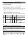
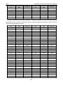
Model - GMV-1175WM/G-X GMV-1230WM/G-X GMV-1295WM/G-X GMV-1360WM/G-X
HP
HP
42
44
46
48
Combination mode
- 20+22 22+22 22+24 24+24
- GMV-560WM/G-X+
GMV-615WM/G-X
GMV-615WM/G-X+
GMV-615WM/G-X
GMV-615WM/G-X+
GMV-680WM/G-X
GMV-680WM/G-X+
GMV-680WM/G-X
Cooling capacity kW 117.5 123.0 129.5 136.0
Heating capacity kW 132.0 138.0 145.5 153.0
Outdoor static
pressure
Pa 0/110 0/110 0/110 0/110
Noise (sound
pressure level)
dB(A) 65 65 65 65
Power -
380V-415V 3N~
50Hz/60Hz
380V-415V 3N~
50Hz/60Hz
380V-415V 3N~
50Hz/60Hz
380V-415V 3N~
50Hz/60Hz
Cooling power input kW 13.8+16.2 16.2+16.2 16.2+20.5 20.5+20.5

Gree GMV6 DC Inverter VRF Units Service Manual
6
Model - GMV-1175WM/G-X GMV-1230WM/G-X GMV-1295WM/G-X GMV-1360WM/G-X
Heating power input kW 13.1+16.9 16.9+16.9 16.9+20.1 20.1+20.1
Cooling current
input
A 24.7+29.0 29.0+29.0 29.0+36.6 36.6+36.6
Heating current
input
A 23.4+30.2 30.2+30.2 30.2+35.9 35.9+35.9
Rated power input kW 26.85+27.41 27.41+27.41 27.41+27.41 27.41+27.41
Rated current A 48+49 49+49 49+49 49+49
Cooling operation
range
°C -5~52 -5~52 -5~52 -5~52
Heating operation
range
°C -30~24 -30~24 -30~24 -30~24
Refrigerant type - R410A R410A R410A R410A
Refrigerant charge kg 8+8.3 8.3+8.3 8.3+8.3 8.3+8.3
Maximum drive IDU
NO.
unit 64 64 64 64
Gas pipe mm Φ38.1 Φ38.1 Φ38.1 Φ41.3
Liquid pipe mm Φ19.05 Φ19.05 Φ19.05 Φ19.05
Outline dimensions
(W × D × H)
mm
1340×775×1690+
1340×775×1690
1340×775×1690+
1340×775×1690
1340×775×1690+
1340×775×1690
1340×775×1690+
1340×775×1690
Packing dimensions
(W × D × H)
mm
1400×830×1855+
1400×830×1855
1400×830×1855+
1400×830×1855
1400×830×1855+
1400×830×1855
1400×830×1855+
1400×830×1855
Net weight kg 350+350 350+350 350+355 355+355
Gross weight kg 365+365 365+365 365+370 370+370
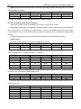
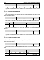
Model - GMV-1399WM/G-X GMV-1455WM/G-X GMV-1510WM/G-X GMV-1565WM/G-X
HP HP 50 52 54 56
Combination mode
- 12+18+20 10+20+22 10+22+22 12+22+22
-
GMV-335WM/G-X+
GMV-504WM/G-X+
GMV-560WM/G-X
GMV-280WM/G-X+
GMV-560WM/G-X+
GMV-615WM/G-X
GMV-280WM/G-X+
GMV-615WM/G-X+
GMV-615WM/G-X
GMV-335WM/G-X+
GMV-615WM/G-X+
GMV-615WM/G-X
Cooling capacity kW 139.9 145.5 151.0 156.5
Heating capacity kW 157.0 163.5 169.5 175.5
Outdoor static
pressure
Pa 0/110 0/110 0/110 0/110
Noise (sound
pressure level)
dB(A) 66 66 67 67
Power -
380V-415V 3N~
50Hz/60Hz
380V-415V 3N~
50Hz/60Hz
380V-415V 3N~
50Hz/60Hz
380V-415V 3N~
50Hz/60Hz
Cooling power input kW 7.7+12.3+13.8 6.2+13.8+16.2 6.2+16.2+16.2 7.7+16.2+16.2
Heating power input kW 7.8+12.9+13.1 5.9+13.1+16.9 5.9+16.9+16.9 7.8+16.9+16.9
Cooling current
input
A 13.8+22.0+24.7 11.1+24.7+29.0 11.1+29.0+29.0 13.8+29.0+29.0
Heating current
input
A 13.9+23.1+23.4 10.5+23.4+30.2 10.5+30.2+30.2 13.9+30.2+30.2
Rated power input kW 13.50+26.30+26.85 13.15+26.85+27.41 13.15+27.41+27.41 13.50+27.41+27.41
Rated current A 24.1+47+48 23.5+48+49 23.5+49+49 24.1+49+49
Cooling operation
range
°C -5~52 -5~52 -5~52 -5~52
Heating operation
range
°C -30~24 -30~24 -30~24 -30~24
Refrigerant type - R410A R410A R410A R410A
Refrigerant charge kg 5.7+8+8 5.5+8+8.3 5.5+8.3+8.3 5.7+8.3+8.3
Maximum drive IDU
NO.
unit 66 69 71 74
Gas pipe mm Φ41.3 Φ41.3 Φ41.3 Φ41.3
Liquid pipe mm Φ19.05 Φ19.05 Φ19.05 Φ19.05
Outline dimensions
(W × D × H) mm
930×775×1690+
1340×775×1690+
1340×775×1690
930×775×1690+
1340×775×1690+
1340×775×1690
930×775×1690+
1340×775×1690+
1340×775×1690
930×775×1690+
1340×775×1690+
1340×775×1690
Packing dimensions
(W × D × H) mm
1000×830×1855+
1400×830×1855+
1400×830×1855
1000×830×1855+
1400×830×1855+
1400×830×1855
1000×830×1855+
1400×830×1855+
1400×830×1855
1000×830×1855+
1400×830×1855+
1400×830×1855
Net weight kg 220+295+350 215+350+350 215+350+350 220+350+350

Gree GMV6 DC Inverter VRF Units Service Manual
7
Model - GMV-1399WM/G-X GMV-1455WM/G-X GMV-1510WM/G-X GMV-1565WM/G-X
Gross weight kg 230+310+365 225+365+365 225+365+365 230+365+365
Model - GMV-1623WM/G-X GMV-1679WM/G-X GMV-1734WM/G-X GMV-1790WM/G-X
HP
HP
58
60
62
64
Combination mode
- 18+18+22 18+20+22 18+22+22 20+22+22
-
GMV-504WM/G-X+
GMV-504WM/G-X+
GMV-615WM/G-X
GMV-504WM/G-X+
GMV-560WM/G-X+
GMV-615WM/G-X
GMV-504WM/G-X+
GMV-615WM/G-X+
GMV-615WM/G-X
GMV-560WM/G-X+
GMV-615WM/G-X+
GMV-615WM/G-X
Cooling capacity kW 162.3 167.9 173.4 179.0
Heating capacity kW 182.0 188.5 194.5 201.0
Outdoor static
pressure
Pa 0/110 0/110 0/110 0/110
Noise (sound
pressure level)
dB(A) 67 67 67 68
Power -
380V-415V 3N~
50Hz/60Hz
380V-415V 3N~
50Hz/60Hz
380V-415V 3N~
50Hz/60Hz
380V-415V 3N~
50Hz/60Hz
Cooling power input kW 12.3+12.3+16.2 12.3+13.8+16.2 12.3+16.2+16.2 13.8+16.2+16.2
Heating power input kW 12.9+12.9+16.9 12.9+13.1+16.9 12.9+16.9+16.9 13.1+16.9+16.9
Cooling current input A 22.0+22.0+29.0 22.0+24.7+29.0 22.0+29.0+29.0 24.7+29.0+29.0
Heating current
input
A 23.1+23.1+30.2 23.1+23.4+30.2 23.1+30.2+30.2 23.4+30.2+30.2
Rated power input kW 26.30+26.30+27.41 26.30+26.85+27.41 26.30+27.41+27.41 26.85+27.41+27.41
Rated current A 47+47+49 47+48+49 47+49+49 48+49+49
Cooling operation
range
°C -5~52 -5~52 -5~52 -5~52
Heating operation
range
°C -30~24 -30~24 -30~24 -30~24
Refrigerant type - R410A R410A R410A R410A
Refrigerant charge kg 8+8+8.3 8+8+8.3 8+8.3+8.3 8+8.3+8.3
Maximum drive IDU
NO.
unit 77 80 80 80
Gas pipe mm Φ41.3 Φ41.3 Φ41.3 Φ41.3
Liquid pipe mm Φ19.05 Φ19.05 Φ19.05 Φ19.05
Outline dimensions
(W x D x H) mm
1340×775×1690+
1340×775×1690+
1340×775×1690
1340×775×1690+
1340×775×1690+
1340×775×1690
1340×775×1690+
1340×775×1690+
1340×775×1690
1340×775×1690+
1340×775×1690+
1340×775×1690
Packing dimensions
(W x D x H) mm
1400×830×1855+
1400×830×1855+
1400×830×1855
1400×830×1855+
1400×830×1855+
1400×830×1855
1400×830×1855+
1400×830×1855+
1400×830×1855
1400×830×1855+
1400×830×1855+
1400×830×1855
Net weight kg 295+295+350 295+350+350 295+350+350 350+350+350
Gross weight kg 310+310+365 310+365+365 310+365+365 365+365+365
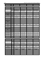
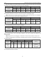
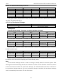
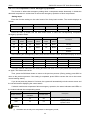
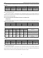
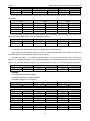
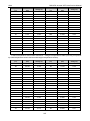
Model - GMV-1845WM/G-X GMV-1910WM/G-X GMV-1975WM/G-X GMV-2040WM/G-X
HP HP 66 68 70 72
Combination mode
- 22+22+22 22+22+24 22+24+24 24+24+24
-
GMV-615WM/G-X+
GMV-615WM/G-X+
GMV-615WM/G-X
GMV-615WM/G-X+
GMV-615WM/G-X+
GMV-680WM/G-X
GMV-615WM/G-X+
GMV-680WM/G-X+
GMV-680WM/G-X
GMV-680WM/G-X+
GMV-680WM/G-X+
GMV-680WM/G-X
Cooling capacity kW 184.5 191.0 197.5 204.0
Heating capacity kW 207.0 214.5 222.0 229.5
Outdoor static
pressure
Pa 0/110 0/110 0/110 0/110
Noise (sound
pressure level)
dB(A) 68 69 69 69
Power -
380V-415V 3N~
50Hz/60Hz
380V-415V 3N~
50Hz/60Hz
380V-415V 3N~
50Hz/60Hz
380V-415V 3N~
50Hz/60Hz
Cooling power input kW 16.2+16.2+16.2 16.2+16.2+20.5 16.2+20.5+20.5 20.5+20.5+20.5
Heating power input kW 16.9+16.9+16.9 16.9+16.9+20.1 16.9+20.1+20.1 20.1+20.1+20.1
Cooling current input A 29.0+29.0+29.0 29.0+29.0+36.6 29.0+36.6+36.6 36.6+36.6+36.6
Heating current input A 30.2+30.2+30.2 30.2+30.2+35.9 30.2+35.9+35.9 35.9+35.9+35.9
Rated power input kW 27.41+27.41+27.41 27.41+27.41+27.41 27.41+27.41+27.41 27.41+27.41+27.41

Gree GMV6 DC Inverter VRF Units Service Manual
8
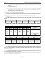
Model - GMV-1845WM/G-X GMV-1910WM/G-X GMV-1975WM/G-X GMV-2040WM/G-X
Rated current A 49+49+49 49+49+49 49+49+49 49+49+49
Cooling operation
range
°C -5~52 -5~52 -5~52 -5~52
Heating operation
range
°C -30~24 -30~24 -30~24 -30~24
Refrigerant type - R410A R410A R410A R410A
Refrigerant charge kg 8.3+8.3+8.3 8.3+8.3+8.3 8.3+8.3+8.3 8.3+8.3+8.3
Maximum drive IDU
NO.
unit 80 80 80 80
Gas pipe mm Φ41.3 Φ44.5 Φ44.5 Φ44.5
Liquid pipe mm Φ19.05 Φ22.2 Φ22.2 Φ22.2
Outline dimensions
(W x D x H) mm
1340×775×1690+
1340×775×1690+
1340×775×1690
1340×775×1690+
1340×775×1690+
1340×775×1690
1340×775×1690+
1340×775×1690+
1340×775×1690
1340×775×1690+
1340×775×1690+
1340×775×1690
Packing dimensions
(W x D x H) mm
1400×830×1855+
1400×830×1855+
1400×830×1855
1400×830×1855+
1400×830×1855+
1400×830×1855
1400×830×1855+
1400×830×1855+
1400×830×1855
1400×830×1855+
1400×830×1855+
1400×830×1855
Net weight kg 350+350+350 350+350+355 350+355+355 355+355+355
Gross weight kg 365+365+365 365+365+370 365+370+370 370+370+370
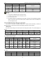
Model - GMV-2069WM/G-X GMV-2129WM/G-X GMV-2190WM/G-X GMV-2245WM/G-X
HP
HP
74
76
78
80
Combination mode
- 12+18+22+22 16+18+20+22 14+20+22+22 14+22+22+22
-
GMV-335WM/G-X+
GMV-504WM/G-X+
GMV-615WM/G-X+
GMV-615WM/G-X
GMV-450WM/G-X+
GMV-504WM/G-X+
GMV-560WM/G-X+
GMV-615WM/G-X
GMV-400WM/G-X+
GMV-560WM/G-X+
GMV-615WM/G-X+
GMV-615WM/G-X
GMV-400WM/G-X+
GMV-615WM/G-X+
GMV-615WM/G-X+
GMV-615WM/G-X
Cooling capacity kW 206.9 212.9 219.0 224.5
Heating capacity kW 232.0 238.5 246.0 252.0
Outdoor static
pressure
Pa 0/110 0/110 0/110 0/110
Noise (sound
pressure level)
dB(A) 68 68 69 69
Power -
380V-415V 3N~
50Hz/60Hz
380V-415V 3N~
50Hz/60Hz
380V-415V 3N~
50Hz/60Hz
380V-415V 3N~
50Hz/60Hz
Cooling power input kW 7.7+12.3+16.2+16.2 10.8+12.3+13.8+16.2 9.2+13.8+16.2+16.2 9.2+16.2+16.2+16.2
Heating power input kW 7.8+12.9+16.9+16.9 10.7+12.9+13.1+16.9 9.5+13.1+16.9+16.9 9.5+16.9+16.9+16.9
Cooling current input A 13.8+22.0+29.0+29.0 19.3+22.0+24.7+29.0 16.4+24.7+29.0+29.0 16.4+29.0+29.0+29.0
Heating current input A 13.9+23.1+30.2+30.2 19.1+23.1+23.4+30.2 17.0+23.4+30.2+30.2 17.0+30.2+30.2+30.2
Rated power input kW
13.50+26.30+
27.41+27.41
18.74+26.30+
26.85+27.41
18.18+26.85+
27.41+27.41
18.18+27.41+
27.41+27.41
Rated current A 24.1+47+49+49 30.2+47+48+49 32.5+48+49+49 32.5+49+49+49
Cooling operation
range
°C -5~52 -5~52 -5~52 -5~52
Heating operation
range
°C -30~24 -30~24 -30~24 -30~24
Refrigerant type - R410A R410A R410A R410A
Refrigerant charge kg 5.7+8+8.3+8.3 7.5+8+8+8.3 7+8+8.3+8.3 7+8.3+8.3+8.3
Maximum drive IDU
NO.
unit 80 80 80 80
Gas pipe mm Φ44.5 Φ44.5 Φ44.5 Φ44.5
Liquid pipe mm Φ22.2 Φ22.2 Φ22.2 Φ22.2
Outline dimensions
(W x D x H) mm
930×775×1690+
1340×775×1690+
1340×775×1690+
1340×775×1690
1340×775×1690+
1340×775×1690+
1340×775×1690+
1340×775×1690
1340×775×1690+
1340×775×1690+
1340×775×1690+
1340×775×1690
1340×775×1690+
1340×775×1690+
1340×775×1690+
1340×775×1690
Packing dimensions
(W x D x H) mm
1000×830×1855+
1400×830×1855+
1400×830×1855+
1400×830×1855
1400×830×1855+
1400×830×1855+
1400×830×1855+
1400×830×1855
1400×830×1855+
1400×830×1855+
1400×830×1855+
1400×830×1855
1400×830×1855+
1400×830×1855+
1400×830×1855+
1400×830×1855
Net weight kg 220+295+350+350 290+295+350+350 290+350+350+350 290+350+350+350
Gross weight kg 230+310+365+365 305+310+365+365 305+365+365+365 305+365+365+365

Gree GMV6 DC Inverter VRF Units Service Manual
9
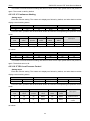
Model - GMV-2295WM/G-X GMV-2350WM/G-X GMV-2414WM/G-X GMV-2470WM/G-X
HP HP 82 84 86 88
Combination mode
- 20+20+20+22 20+20+22+22 18+22+22+24 20+22+22+24
-
GMV-560WM/G-X+
GMV-560WM/G-X+
GMV-560WM/G-X+
GMV-615WM/G-X
GMV-560WM/G-X+
GMV-560WM/G-X+
GMV-615WM/G-X+
GMV-615WM/G-X
GMV-504WM/G-X+
GMV-615WM/G-X+
GMV-615WM/G-X+
GMV-680WM/G-X
GMV-560WM/G-X+
GMV-615WM/G-X+
GMV-615WM/G-X+
GMV-680WM/G-X
Cooling capacity kW 229.5 235.0 241.4 247.0
Heating capacity kW 258.0 264.0 271.0 277.5
Outdoor static
pressure
Pa 0/110 0/110 0/110 0/110
Noise (sound
pressure level)
dB(A) 69 69 69 70
Power -
380V-415V 3N~
50Hz/60Hz
380V-415V 3N~
50Hz/60Hz
380V-415V 3N~
50Hz/60Hz
380V-415V 3N~
50Hz/60Hz
Cooling power input kW 13.8+13.8+13.8+16.2
13.8+13.8+16.2+16.
2
12.3+16.2+16.2+
20.5
13.8+16.2+16.2+20.
5
Heating power input kW 13.1+13.1+13.1+16.9
13.1+13.1+16.9+16.
9
12.9+16.9+16.9+20.
1
13.1+16.9+16.9+20.
1
Cooling current input A
24.7+24.7+24.7+
29.0
24.7+24.7+29.0+
29.0
22.0+29.0+29.0+
36.6
24.7+29.0+29.0+
36.6
Heating current
input
A
23.4+23.4+23.4+
30.2
23.4+23.4+30.2+
30.2
23.1+30.2+30.2+
35.9
23.4+30.2+30.2+
35.9
Rated power input kW
26.85+26.85+26.85+2
7.41
26.85+26.85+27.41+
27.41
26.30+27.41+27.41+
27.41
26.85+27.41+27.41+
27.41
Rated current A
48+48+48+
49
48+48+49+
49
47+49+49+
49
48+49+49+
49
Cooling operation
range
°C -5~52 -5~52 -5~52 -5~52
Heating operation
range
°C -30~24 -30~24 -30~24 -30~24
Refrigerant type - R410A R410A R410A R410A
Refrigerant charge kg 8+8+8+8.3 8+8+8.3+8.3 8+8.3+8.3+8.3 8+8.3+8.3+8.3
Maximum drive IDU
NO.
unit 80 80 80 80
Gas pipe mm Φ44.5 Φ44.5 Φ44.5 Φ44.5
Liquid pipe mm Φ22.2 Φ22.2 Φ22.2 Φ22.2
Outline dimensions
(W x D x H) mm
1340×775×1690+
1340×775×1690+
1340×775×1690+
1340×775×1690
1340×775×1690+
1340×775×1690+
1340×775×1690+
1340×775×1690
1340×775×1690+
1340×775×1690+
1340×775×1690+
1340×775×1690
1340×775×1690+
1340×775×1690+
1340×775×1690+
1340×775×1690
Packing dimensions
(W x D x H) mm
1400×830×1855+
1400×830×1855+
1400×830×1855+
1400×830×1855
1400×830×1855+
1400×830×1855+
1400×830×1855+
1400×830×1855
1400×830×1855+
1400×830×1855+
1400×830×1855+
1400×830×1855
1400×830×1855+
1400×830×1855+
1400×830×1855+
1400×830×1855
Net weight kg 350+350+350+350 350+350+350+350 295+350+350+355 350+350+350+355
Gross weight kg 365+365+365+365 365+365+365+365 310+365+365+370 365+365+365+370
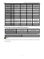
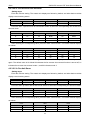
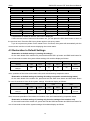
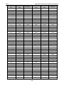
Model - GMV-2525WM/G-X GMV-2590WM/G-X GMV-2655WM/G-X GMV-2720WM/G-X
HP HP 90 92 94 96
Combination mode
- 22+22+22+24 22+22+24+24 22+24+24+24 24+24+24+24
-
GMV-615WM/G-X+
GMV-615WM/G-X+
GMV-615WM/G-X+
GMV-680WM/G-X
GMV-615WM/G-X+
GMV-615WM/G-X+
GMV-680WM/G-X+
GMV-680WM/G-X
GMV-615WM/G-X+
GMV-680WM/G-X+
GMV-680WM/G-X+
GMV-680WM/G-X
GMV-680WM/G-X+
GMV-680WM/G-X+
GMV-680WM/G-X+
GMV-680WM/G-X
Cooling capacity kW 252.5 259.0 265.5 272.0
Heating capacity kW 283.5 291.0 298.5 306.0
Outdoor static
pressure
Pa 0/110 0/110 0/110 0/110
Noise (sound
pressure level)
dB(A) 70 70 70 70
Power -
380V-415V 3N~
50Hz/60Hz
380V-415V 3N~
50Hz/60Hz
380V-415V 3N~
50Hz/60Hz
380V-415V 3N~
50Hz/60Hz
Cooling power input kW
16.2+16.2+16.2+
20.5
16.2+16.2+20.5+
20.5
16.2+20.5+20.5+
20.5
20.5+20.5+20.5+
20.5
Heating power input kW
16.9+16.9+16.9+
20.1
16.9+16.9+20.1+
20.1
16.9+20.1+20.1+
20.1
20.1+20.1+20.1+
20.1

Gree GMV6 DC Inverter VRF Units Service Manual
10
Model - GMV-2525WM/G-X GMV-2590WM/G-X GMV-2655WM/G-X GMV-2720WM/G-X
Cooling current
input
A
29.0+29.0+29.0+
36.6
29.0+29.0+36.6+
36.6
29.0+36.6+36.6+
36.6
36.6+36.6+36.6+36.6
Heating current
input
A
30.2+30.2+30.2+
35.9
30.2+30.2+35.9+
35.9
30.2+35.9+35.9+
35.9
35.9+35.9+35.9+
35.9
Rated power input kW
27.41+27.41+27.41+
27.41
27.41+27.41+27.41+
27.41
27.41+27.41+27.41
+27.41
27.41+27.41+27.41+2
7.41
Rated current A
49+49+49+
49
49+49+49+
49
49+49+49+
49
49+49+49+
49
Cooling operation
range
°C -5~52 -5~52 -5~52 -5~52
Heating operation
range
°C -30~24 -30~24 -30~24 -30~24
Refrigerant type - R410A R410A R410A R410A
Refrigerant charge kg 8.3+8.3+8.3+8.3 8.3+8.3+8.3+8.3 8.3+8.3+8.3+8.3 8.3+8.3+8.3+8.3
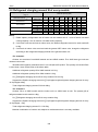
Maximum drive IDU
NO.
unit 80(85)* 80(90)* 80(95)* 80(100)*
Gas pipe mm Φ44.5 Φ44.5 Φ44.5 Φ44.5
Liquid pipe mm Φ22.2 Φ22.2 Φ22.2 Φ22.2
Outline dimensions
(W x D x H) mm
1340×775×1690+
1340×775×1690+
1340×775×1690+
1340×775×1690
1340×775×1690+
1340×775×1690+
1340×775×1690+
1340×775×1690
1340×775×1690+
1340×775×1690+
1340×775×1690+
1340×775×1690
1340×775×1690+
1340×775×1690+
1340×775×1690+
1340×775×1690
Packing dimensions
(W x D x H) mm
1400×830×1855+
1400×830×1855+
1400×830×1855+
1400×830×1855
1400×830×1855+
1400×830×1855+
1400×830×1855+
1400×830×1855
1400×830×1855+
1400×830×1855+
1400×830×1855+
1400×830×1855
1400×830×1855+
1400×830×1855+
1400×830×1855+
1400×830×1855
Net weight kg 350+350+350+355 350+350+355+355 350+355+355+355 355+355+355+355
Gross weight kg 365+365+365+370 365+365+370+370 365+370+370+370 370+370+370+370
Note:*The maximum connection quantity of indoor unit in the brace should be engineering customized.
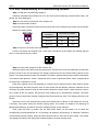
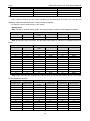
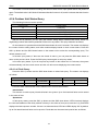
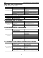
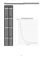
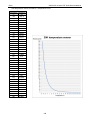
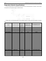
3 The Range of Production Working Temperature
—
Cooling
Heating
Ambient temperature
-5°C ~52°C DB
-30°C ~24°C DB
Indoor temperature
14°C ~25°C WB
15°C ~27°C DB
Indoor humidity
≤80%
When the indoor units are all VRF fresh air processor, the unit operating range is as follows:
Cooling
Ambient temperature: 16°C ~45°C
Heating
Ambient temperature: -7°C ~16°C
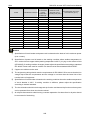
NOTE!
If exceeding the temperature range for working, the product may be damaged, which is not within
the warranty range.

Gree GMV6 DC Inverter VRF Units Service Manual
11
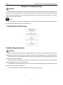
Chapter 2 Commissioning
WARNING!
Before performing operations (such as commissioning, maintenance, and repair) on the device, you
need to shut down the unit and cut off the power, and use a relevant instrument to ensure that the voltage
at the power input terminal is zero, and the power indicator on the main board is off. Otherwise, an electric
shock or injury may be caused.
NOTE!
The unit features a low-power standby function. When the unit is standby, the power indicators on
the main control board and the drive board are on.
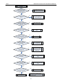
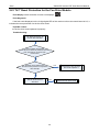
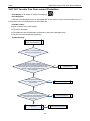
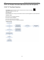
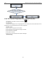
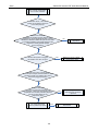
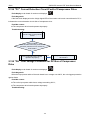
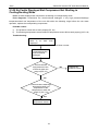
1 Commissioning Process
Preparation before
commissioning
Verification of installation
Unit checking
Commissioning
2 Safety Requirements
WARNING!
Safety measures must be taken for outdoor operations. All involved commissioning personnel and
maintenance personnel must master the building construction safety regulations and strictly follow them.
Special workers like refrigeration workers, electricians, and welders must hold special work licenses
and cannot work on other posts.
When the device is operated, the power of the entire system must be cut off, and the equipment
safety requirements must be strictly followed.
All installation and maintenance operations must comply with the product design requirements and
national and local safety requirements.
It is strictly forbidden to directly connect the compressor to the power.

Gree GMV6 DC Inverter VRF Units Service Manual
12
3 Unit Commissioning
3.1 Preparation
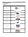
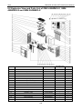
3.1.1 Tools
Name
Picture
Screwdrivers
Spanner
Hex key
Pincers
Vacuum pump
Electronic balance
Pressure gauge
Multimeter

Gree GMV6 DC Inverter VRF Units Service Manual
13
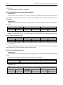
3.1.2 Files
To record the installation and commissioning of the unit, all the following documents need to be
prepared: minutes of the pre-commissioning scheme determining meeting, commissioning personnel
record form, pre-commissioning checklist, commissioning data record form, and commissioning report.
Minutes of the commissioning scheme determining meeting:
Minutes of the commissioning scheme determining meeting for XXX project:
Theme: xxx
Date: xxx
Place: xxx
Participants: xxx
Details: xxx
1
2
3
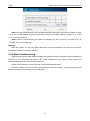
Checklist of the commissioning system appearance:
Checklist of the equipment appearance of xxx air-conditioning project
Item Defect Inspector Time
Refrigerating
system
Outdoor unit
appearance
Indoor unit
appearance
Copper pipe
insulation
Drainage system
Condensate
water pipe
insulation
Electrical system
Power cable
diameter
Power cable
layout
Air circuit
breaker
Communication
system
Communication
cable material
Communication
cable
connection

Gree GMV6 DC Inverter VRF Units Service Manual
14
Commissioning data record form
Project name:
Unit model:
Debugger:
Date:
Rated capacity of
the outdoor unit
(kW):
Rated capacity of
the indoor unit
(kW):
Total length of the
refrigerant pipe
(m):
Maximum drop
between the
indoor unit and
outdoor unit (m):
Supplemented refrigerant (kg):
Commissioning status: □ Cooling □ Heating Qty and capacity of indoor units:
Status Parameter Unit Before Startup 30 min 60 min
Status parameters of the outdoor unit
Outdoor ambient
temperature
°C
Power voltage
V
Frequency
Hz
Compressor current
A
Discharge
temperature
°C
High system
pressure
°C
Low system
pressure
°C
...
Parameters of indoor unit 1#
Rated capacity kW
Ambient
temperature
°C
Air position
Position
Temperature at the
air outlet
°C
Outlet airflow
M/S
Noise
dB
Drainage pan —
Parameters of indoor unit 2#
Rated capacity kW
Ambient
temperature
°C
Air position
Position
Temperature at the
air outlet
°C
Outlet airflow
M/S
Noise
dB
Drainage pan —

Gree GMV6 DC Inverter VRF Units Service Manual
15
3.1.3 Checking
NOTE!
Items not complying with installation specifications need to be recorded in time as analysis basis for
the test of the refrigerating system.
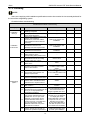
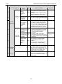
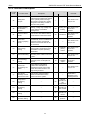
Checklist before commissioning
Checklist Before GMV6 Commissioning
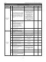
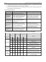
Category No. Item Reference Value Qualified Inspector
Installation
drawings
1
Are the engineering design
drawings complete?
—
2 Is the project constructed according
to the design drawings?
—
Installation
environment
3
Is there any pollution source in the
outdoor unit installation
environment, and is the outdoor
unit installation location selected
correctly?
Refer to the outdoor unit
installation.
4
Is the outdoor unit foundation firm?
Do vibration reduction and
drainage meet the requirements?
Refer to the outdoor unit
installation.
5 Are the outdoor unit basic modules
installed at the same level?
Refer to the outdoor unit
installation.
6
Does the outdoor unit operate with
static pressure? Is the
corresponding static pressure set?
—
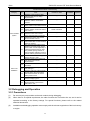
Refrigerating
system
7
Is the rated capacity of the internal
and external units of the cooling
system within 50%~135%?
50% to 135%
8 Is the fresh air unit access capacity
within 30%? ≤30%
9 Is GMV6 connected to outdoor
units in other series?
GMV6 cannot be connected
to outdoor units in other
series.
10
Does the drop between the indoor
and outdoor units meet the unit
design requirements?
≤110 m with the outdoor unit
up
≤110 m with the outdoor unit
down
11 Does the drop between indoor units
meet the unit design requirements? ≤40 m
12
Is the length of the pipe from the
outdoor unit to the farthest indoor
unit less than or equal to 200 m?
≤200m
13 Is the total length of the piping less
than 1000 m? ≤1000 m
14
Is the length of the outdoor unit to
the first branch joint greater than 90
m? If yes, is the pipe diameter
increased accordingly?
The pipe diameter needs to
be increased when the
length is greater than 90 m.
15
Is the distance between an indoor
unit and the nearest branch joint
greater than 15 m? If yes, is the
diameter of a liquid pipe whose
original diameter is less than or
equal to 6.35 mm, or the diameter
of a gas pipe whose original
diameter is less than or equal to
9.52 mm be increased?
≤15 m. When the length
exceeds 10 m, the diameter
of a liquid pipe whose
original diameter is less than
or equal to 6.35 mm, or the
diameter of a gas pipe
whose original diameter is
less than or equal to 9.52
mm needs to be increased.
16
The inclination of indoor and
outdoor branch joints should not
exceed the specified requirements.
Branch joints need to be
installed horizontally. Refer
to branch joint installation.

Gree GMV6 DC Inverter VRF Units Service Manual
16
Checklist Before GMV6 Commissioning
Category No. Item Reference Value Qualified Inspector
Refrigerating
system
17 Is the stop valve of each module
open to the maximum opening? —
18
Is the refrigerant pressure normal?
Connect the high pressure gauge
of the pressure gauge to the liquid
pipe valve of the outdoor unit,
connect the low pressure gauge to
the gas pipe valve, and read the
value.
At this time, the high and
low pressures of the system
are in balance, and the
difference between the
saturation temperature
corresponding to the
balanced pressure value
and the ambient
temperature (higher one of
the indoor and outdoor
temperatures) does not
exceed 5°C. If it exceeds
5°C, check for the outdoor
unit leakage.
19
Is there any leakage of chiller oil at
the valve?
If so, immediately check for valve
leakage with soap bubbles or a
leak detector. If leakage is
confirmed, stop subsequent
commissioning at once, and
continue the work only after the
problem is solved.
—
20
Is the outdoor unit being warmed
up for more than 2 hours before
commissioning?
—
Electrical
system
21
Is the power cable connected
correctly? Is the terminal block
secure?
—
22 Is the power cable appearance in
good condition and not exposed?
The appearance is in good
condition and not exposed.
23 Is the power capacity less than the
maximum power of the unit?
The power capacity is not
less than the maximum
power of the unit.
24
Is there any poorly connected
electrical component detected
when the power is off?
All components are reliably
connected.
25
Do the cable diameters of the
indoor and outdoor units meet the
unit design requirements?
Refer to electrical
installation.
26
Do the circuit breaker and leakage
switch meet the unit design
requirements?
Refer to electrical
installation.
27
Do the power voltage, phase
sequence, and frequency meet the
unit requirements?
The power voltage, phase
sequence, and frequency
are consistent with those on
the unit nameplate, and the
voltage fluctuates within
±10%.
28 Is the power cable more than 1 m
away from a TV? —
29
Is there any strong electromagnetic
interference, dust, acid and alkaline
gas in the environment where the
unit is located?
—

Gree GMV6 DC Inverter VRF Units Service Manual
17
Checklist Before GMV6 Commissioning
Category No. Item Reference Value Qualified Inspector
Communication
system
30
Does the communication cable
material meet the unit design
requirements?
—
31
Is the communication connection
between outdoor unit modules
correct?
—
32 Is the DIP switch of the master unit
of the outdoor unit module correct? —
33
Is the communication between the
outdoor master unit and the indoor
unit correct?
Serial connection
34 Is the communication connection
between indoor units correct? —
35
Is the communication connection
between the indoor unit and the
wired controller correct?
—
36
Is the last communication indoor
unit installed with a communication
build-out resistor?
—
37
The communication cable cannot
be laid in the same trough as the
power cable. It is laid separately in
a flame-retardant hard PVC pipe.
The parallel spacing between a
communication cable and a strong-
current cable is greater than 20 cm.
—
Indoor unit
installation
38 Does the indoor unit drain pipe
have a slope of 1/100? —
39
Does the height of the indoor unit
riser drain pipe meet the
requirements?
—
40 Does the indoor unit drain
smoothly? —
41 Is there a U-shaped trap for indoor
unit drainage? —
42
Is there a soft joint at the air outlet
and air return vent of the indoor
unit? Does the return air have a
static pressure box?
—
43 Does the indoor unit water pipe
have an emptying port? —
44
Is a "main" label attached to the
wired controller or panel of the
main indoor unit?
—
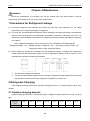
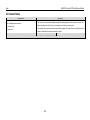
3.2 Debugging and Operation
3.2.1 Precautions
(1) Do set one (only one) module as the main module during debugging.
(2) When there is no special requirement, the other functions do not need to be set, and it can be
operated according to the factory settings. For special functions, please refer to the related
technical documents.
(3) Installation and debugging operation must comply with the relevant regulations of the local country
or region.

Gree GMV6 DC Inverter VRF Units Service Manual
18
(4) Debugging must be carried out by a professional or under the guidance of a professional. Do not
debug the air conditioning unit by yourself.
(5) All scattered objects, especially metal chips, wire ends and clamps, should be removed from the
body.
(6) Check if the terminals of the electrical components in the unit are loose and the phase sequence
is correct.
(7) Before debugging, all pipeline valves of the unit are required to be open.
(8) Power cannot be supplied until all installation work is completed.
(9) Before conducting the debugging, please ensure that the compressor has been preheated for
more than 2 hours, and check whether the preheating is normal by hand. Debugging can be started
up only when the preheating is normal, otherwise the compressor may be damaged.
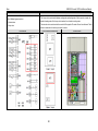
(10) When starting up the debugging, the system automatically selects the operating mode according
to the current ambient temperature.
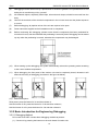
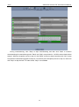
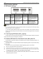
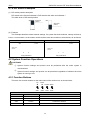
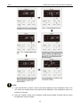
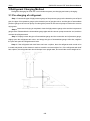
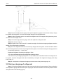
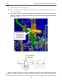
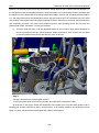
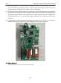
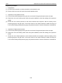
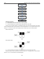
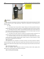
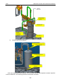
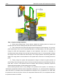
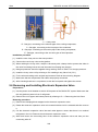
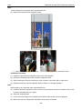
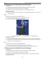
(11) When debugging, the front panel of the outdoor unit must be completely closed, otherwise it will
affect the accuracy of debugging (as shown in the figure as below).
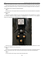
(12) Button description:
Short press: press the button for 3s and then release it;
Hold the button for 5s: press the button for 5-10s and then release it;
Hold the button for 10s: press the button for 10s and then release it.
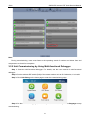
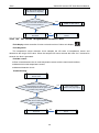
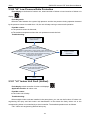
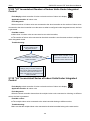
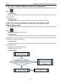
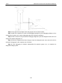
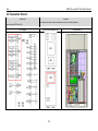
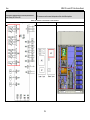
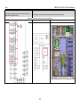
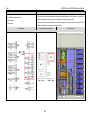
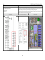
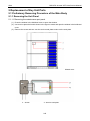
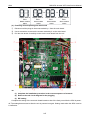
3.2.2 Basic Introduction for Engineering Debugging
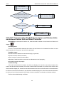
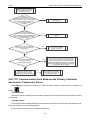
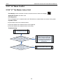
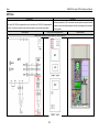
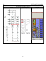
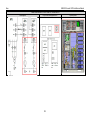
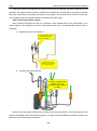
3.2.2.1 Debugging Method
DC inverter multi VRF unit has three debugging methods at present:
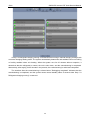
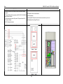
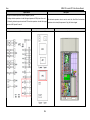
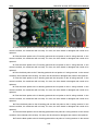
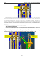
(1) Conduct it by pressing the buttons on the main board of outdoor unit.
Page is loading ...
Page is loading ...
Page is loading ...
Page is loading ...
Page is loading ...
Page is loading ...
Page is loading ...
Page is loading ...
Page is loading ...
Page is loading ...
Page is loading ...
Page is loading ...
Page is loading ...
Page is loading ...
Page is loading ...
Page is loading ...
Page is loading ...
Page is loading ...
Page is loading ...
Page is loading ...
Page is loading ...
Page is loading ...
Page is loading ...
Page is loading ...
Page is loading ...
Page is loading ...
Page is loading ...
Page is loading ...
Page is loading ...
Page is loading ...
Page is loading ...
Page is loading ...
Page is loading ...
Page is loading ...
Page is loading ...
Page is loading ...
Page is loading ...
Page is loading ...
Page is loading ...
Page is loading ...
Page is loading ...
Page is loading ...
Page is loading ...
Page is loading ...
Page is loading ...
Page is loading ...
Page is loading ...
Page is loading ...
Page is loading ...
Page is loading ...
Page is loading ...
Page is loading ...
Page is loading ...
Page is loading ...
Page is loading ...
Page is loading ...
Page is loading ...
Page is loading ...
Page is loading ...
Page is loading ...
Page is loading ...
Page is loading ...
Page is loading ...
Page is loading ...
Page is loading ...
Page is loading ...
Page is loading ...
Page is loading ...
Page is loading ...
Page is loading ...
Page is loading ...
Page is loading ...
Page is loading ...
Page is loading ...
Page is loading ...
Page is loading ...
Page is loading ...
Page is loading ...
Page is loading ...
Page is loading ...
Page is loading ...
Page is loading ...
Page is loading ...
Page is loading ...
Page is loading ...
Page is loading ...
Page is loading ...
Page is loading ...
Page is loading ...
Page is loading ...
Page is loading ...
Page is loading ...
Page is loading ...
Page is loading ...
Page is loading ...
Page is loading ...
Page is loading ...
Page is loading ...
Page is loading ...
Page is loading ...
Page is loading ...
Page is loading ...
Page is loading ...
Page is loading ...
Page is loading ...
Page is loading ...
Page is loading ...
Page is loading ...
Page is loading ...
Page is loading ...
Page is loading ...
Page is loading ...
Page is loading ...
Page is loading ...
Page is loading ...
Page is loading ...
Page is loading ...
Page is loading ...
Page is loading ...
Page is loading ...
Page is loading ...
Page is loading ...
Page is loading ...
Page is loading ...
Page is loading ...
Page is loading ...
Page is loading ...
Page is loading ...
Page is loading ...
Page is loading ...
Page is loading ...
Page is loading ...
Page is loading ...
Page is loading ...
Page is loading ...
Page is loading ...
Page is loading ...
Page is loading ...
Page is loading ...
Page is loading ...
Page is loading ...
Page is loading ...
Page is loading ...
Page is loading ...
Page is loading ...
Page is loading ...
Page is loading ...
Page is loading ...
Page is loading ...
Page is loading ...
Page is loading ...
Page is loading ...
Page is loading ...
Page is loading ...
Page is loading ...
Page is loading ...
Page is loading ...
Page is loading ...
Page is loading ...
Page is loading ...
Page is loading ...
Page is loading ...
Page is loading ...
Page is loading ...
Page is loading ...
Page is loading ...
Page is loading ...
Page is loading ...
Page is loading ...
Page is loading ...
Page is loading ...
Page is loading ...
Page is loading ...
Page is loading ...
Page is loading ...
Page is loading ...
Page is loading ...
Page is loading ...
Page is loading ...
Page is loading ...
Page is loading ...
Page is loading ...
Page is loading ...
Page is loading ...
Page is loading ...
Page is loading ...
Page is loading ...
Page is loading ...
Page is loading ...
Page is loading ...
Page is loading ...
Page is loading ...
Page is loading ...
Page is loading ...
Page is loading ...
Page is loading ...
Page is loading ...
Page is loading ...
Page is loading ...
Page is loading ...
Page is loading ...
Page is loading ...
Page is loading ...
Page is loading ...
Page is loading ...
Page is loading ...
Page is loading ...
Page is loading ...
Page is loading ...
Page is loading ...
Page is loading ...
Page is loading ...
Page is loading ...
Page is loading ...
Page is loading ...
Page is loading ...
Page is loading ...
Page is loading ...
Page is loading ...
Page is loading ...
Page is loading ...
Page is loading ...
Page is loading ...
Page is loading ...
Page is loading ...
Page is loading ...
Page is loading ...
Page is loading ...
Page is loading ...
Page is loading ...
Page is loading ...
Page is loading ...
Page is loading ...
Page is loading ...
Page is loading ...
Page is loading ...
Page is loading ...
Page is loading ...
Page is loading ...
Page is loading ...
Page is loading ...
Page is loading ...
Page is loading ...
Page is loading ...
Page is loading ...
Page is loading ...
Page is loading ...
Page is loading ...
Page is loading ...
Page is loading ...
Page is loading ...
Page is loading ...
Page is loading ...
Page is loading ...
Page is loading ...
Page is loading ...
Page is loading ...
Page is loading ...
Page is loading ...
Page is loading ...
Page is loading ...
Page is loading ...
Page is loading ...
Page is loading ...
Page is loading ...
Page is loading ...
Page is loading ...
Page is loading ...
Page is loading ...
Page is loading ...
Page is loading ...
Page is loading ...
Page is loading ...
Page is loading ...
Page is loading ...
Page is loading ...
Page is loading ...
Page is loading ...
Page is loading ...
Page is loading ...
Page is loading ...
Page is loading ...
Page is loading ...
Page is loading ...
Page is loading ...
-
 1
1
-
 2
2
-
 3
3
-
 4
4
-
 5
5
-
 6
6
-
 7
7
-
 8
8
-
 9
9
-
 10
10
-
 11
11
-
 12
12
-
 13
13
-
 14
14
-
 15
15
-
 16
16
-
 17
17
-
 18
18
-
 19
19
-
 20
20
-
 21
21
-
 22
22
-
 23
23
-
 24
24
-
 25
25
-
 26
26
-
 27
27
-
 28
28
-
 29
29
-
 30
30
-
 31
31
-
 32
32
-
 33
33
-
 34
34
-
 35
35
-
 36
36
-
 37
37
-
 38
38
-
 39
39
-
 40
40
-
 41
41
-
 42
42
-
 43
43
-
 44
44
-
 45
45
-
 46
46
-
 47
47
-
 48
48
-
 49
49
-
 50
50
-
 51
51
-
 52
52
-
 53
53
-
 54
54
-
 55
55
-
 56
56
-
 57
57
-
 58
58
-
 59
59
-
 60
60
-
 61
61
-
 62
62
-
 63
63
-
 64
64
-
 65
65
-
 66
66
-
 67
67
-
 68
68
-
 69
69
-
 70
70
-
 71
71
-
 72
72
-
 73
73
-
 74
74
-
 75
75
-
 76
76
-
 77
77
-
 78
78
-
 79
79
-
 80
80
-
 81
81
-
 82
82
-
 83
83
-
 84
84
-
 85
85
-
 86
86
-
 87
87
-
 88
88
-
 89
89
-
 90
90
-
 91
91
-
 92
92
-
 93
93
-
 94
94
-
 95
95
-
 96
96
-
 97
97
-
 98
98
-
 99
99
-
 100
100
-
 101
101
-
 102
102
-
 103
103
-
 104
104
-
 105
105
-
 106
106
-
 107
107
-
 108
108
-
 109
109
-
 110
110
-
 111
111
-
 112
112
-
 113
113
-
 114
114
-
 115
115
-
 116
116
-
 117
117
-
 118
118
-
 119
119
-
 120
120
-
 121
121
-
 122
122
-
 123
123
-
 124
124
-
 125
125
-
 126
126
-
 127
127
-
 128
128
-
 129
129
-
 130
130
-
 131
131
-
 132
132
-
 133
133
-
 134
134
-
 135
135
-
 136
136
-
 137
137
-
 138
138
-
 139
139
-
 140
140
-
 141
141
-
 142
142
-
 143
143
-
 144
144
-
 145
145
-
 146
146
-
 147
147
-
 148
148
-
 149
149
-
 150
150
-
 151
151
-
 152
152
-
 153
153
-
 154
154
-
 155
155
-
 156
156
-
 157
157
-
 158
158
-
 159
159
-
 160
160
-
 161
161
-
 162
162
-
 163
163
-
 164
164
-
 165
165
-
 166
166
-
 167
167
-
 168
168
-
 169
169
-
 170
170
-
 171
171
-
 172
172
-
 173
173
-
 174
174
-
 175
175
-
 176
176
-
 177
177
-
 178
178
-
 179
179
-
 180
180
-
 181
181
-
 182
182
-
 183
183
-
 184
184
-
 185
185
-
 186
186
-
 187
187
-
 188
188
-
 189
189
-
 190
190
-
 191
191
-
 192
192
-
 193
193
-
 194
194
-
 195
195
-
 196
196
-
 197
197
-
 198
198
-
 199
199
-
 200
200
-
 201
201
-
 202
202
-
 203
203
-
 204
204
-
 205
205
-
 206
206
-
 207
207
-
 208
208
-
 209
209
-
 210
210
-
 211
211
-
 212
212
-
 213
213
-
 214
214
-
 215
215
-
 216
216
-
 217
217
-
 218
218
-
 219
219
-
 220
220
-
 221
221
-
 222
222
-
 223
223
-
 224
224
-
 225
225
-
 226
226
-
 227
227
-
 228
228
-
 229
229
-
 230
230
-
 231
231
-
 232
232
-
 233
233
-
 234
234
-
 235
235
-
 236
236
-
 237
237
-
 238
238
-
 239
239
-
 240
240
-
 241
241
-
 242
242
-
 243
243
-
 244
244
-
 245
245
-
 246
246
-
 247
247
-
 248
248
-
 249
249
-
 250
250
-
 251
251
-
 252
252
-
 253
253
-
 254
254
-
 255
255
-
 256
256
-
 257
257
-
 258
258
-
 259
259
-
 260
260
-
 261
261
-
 262
262
-
 263
263
-
 264
264
-
 265
265
-
 266
266
-
 267
267
-
 268
268
-
 269
269
-
 270
270
-
 271
271
-
 272
272
-
 273
273
-
 274
274
-
 275
275
-
 276
276
-
 277
277
-
 278
278
-
 279
279
-
 280
280
-
 281
281
-
 282
282
-
 283
283
-
 284
284
-
 285
285
-
 286
286
-
 287
287
-
 288
288
-
 289
289
-
 290
290
-
 291
291
-
 292
292
-
 293
293
-
 294
294
-
 295
295
-
 296
296
-
 297
297
-
 298
298
-
 299
299
-
 300
300
-
 301
301
-
 302
302
-
 303
303
-
 304
304
-
 305
305


GREE GMV-1910WM/G-X User manual
- Category
- Split-system air conditioners
- Type
- User manual
- This manual is also suitable for
Ask a question and I''ll find the answer in the document
Finding information in a document is now easier with AI
Related papers
Other documents
-
 SystemAir SYS CWC TOUCH 6.2 Owner's manual
-
Argo PACKAGE R32 OU- AEGECO85PIH User manual
-
Sinclair ASD-24BI2 User manual
-
 Kaysun Individual Wireless Controller KI-04 S User manual
-
-
Lennox F1943L-3P User manual
-
 Jntech JNP45KH-V5 Quick Installation
-
 ACPro GMV-72WM/B-FU Owner's manual
-
 Kaysun Individual Wireless Controller KI-05 User manual
-
ActronAir Controls User manual


