Skope SL295 Speed Lane Chiller User manual
- Type
- User manual

SL295
User Manual
MAN1554 Rev. 2.2 Sep. 2022
SKOPE Speed Lane Chiller

SL295
SKOPE Speed Lane Chiller
User Manual
MAN1554
Rev. 2.2 Sep. 2022
Copyright © 2005
SKOPE Industries Limited. All rights reserved.
SKOPE Industries Limited reserves the right to alter specifications without notice.
is a registered trademark of SKOPE Industries Limited.
SKOPE INDUSTRIES LIMITED
Head Office
PO Box 1091, Christchurch
New Zealand
A.B.N. 73 374 418 306
AU: 1800 121 535
NZ: 0800 947 5673
E-mail: [email protected]
Website: www.skope.com
Trademark Infringement
The SKOPE trademark on this product is infringed if the owner, for the time being, does any of the following:
• Applies the trade mark to the product after its state, condition, get-up or packaging has been altered in
any manner
• Alters, removes (including part removal) or obliterates (including part obliteration) the trade mark on the
product
• Applies any other trade mark to the product
• Adds to the product any written material that is likely to damage the reputation of the trade mark
Notice of the above contractual obligations passes to:
• Successors or assignees of the buyer
• Future owners of the product

SKOPE SL295
User Manual iii
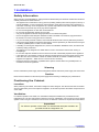
Contents
1 Installation
Safety Information . . . . . . . . . . . . . . . . . . . . . . . . . . . . . . . . . . . . . . . 4
Positioning the Cabinet . . . . . . . . . . . . . . . . . . . . . . . . . . . . . . . . . . . 4
Location . . . . . . . . . . . . . . . . . . . . . . . . . . . . . . . . . . . . . . . . . . . . . 4
Ventilation . . . . . . . . . . . . . . . . . . . . . . . . . . . . . . . . . . . . . . . . . . . 4
Installation Guidelines . . . . . . . . . . . . . . . . . . . . . . . . . . . . . . . . . . 5
Power Supply . . . . . . . . . . . . . . . . . . . . . . . . . . . . . . . . . . . . . . . . 5
Fitting Kick Panels . . . . . . . . . . . . . . . . . . . . . . . . . . . . . . . . . . . . . . . 5
Fitting Shelves . . . . . . . . . . . . . . . . . . . . . . . . . . . . . . . . . . . . . . . . . . 5
2 Operation
Loading . . . . . . . . . . . . . . . . . . . . . . . . . . . . . . . . . . . . . . . . . . . . . . . 6
Operating the Cabinet . . . . . . . . . . . . . . . . . . . . . . . . . . . . . . . . . . . . 6
Refrigeration Cartridge . . . . . . . . . . . . . . . . . . . . . . . . . . . . . . . . . 6
Electronic Controller . . . . . . . . . . . . . . . . . . . . . . . . . . . . . . . . . . . 6
Cabinet Interior Lights . . . . . . . . . . . . . . . . . . . . . . . . . . . . . . . . . . 6
3 Electronic Controller
Overview . . . . . . . . . . . . . . . . . . . . . . . . . . . . . . . . . . . . . . . . . . . . . . 7
CAREL S4 EVO. . . . . . . . . . . . . . . . . . . . . . . . . . . . . . . . . . . . . . . . . 7
Overview . . . . . . . . . . . . . . . . . . . . . . . . . . . . . . . . . . . . . . . . . . . . 7
Faceplate. . . . . . . . . . . . . . . . . . . . . . . . . . . . . . . . . . . . . . . . . . . . 7
Lights . . . . . . . . . . . . . . . . . . . . . . . . . . . . . . . . . . . . . . . . . . . . . . . 8
Temperature Setpoint . . . . . . . . . . . . . . . . . . . . . . . . . . . . . . . . . . 8
Messages and Alarms . . . . . . . . . . . . . . . . . . . . . . . . . . . . . . . . . . 8
CAREL ir33 . . . . . . . . . . . . . . . . . . . . . . . . . . . . . . . . . . . . . . . . . . . . 9
Controller Display . . . . . . . . . . . . . . . . . . . . . . . . . . . . . . . . . . . . . 9
Temperature Setpoint . . . . . . . . . . . . . . . . . . . . . . . . . . . . . . . . . 10
Alarms . . . . . . . . . . . . . . . . . . . . . . . . . . . . . . . . . . . . . . . . . . . . . 11
4 Servicing
Cleaning. . . . . . . . . . . . . . . . . . . . . . . . . . . . . . . . . . . . . . . . . . . . . . 12
Condenser Coil and Optional Air Filter . . . . . . . . . . . . . . . . . . . . 13
Lighting . . . . . . . . . . . . . . . . . . . . . . . . . . . . . . . . . . . . . . . . . . . . . . 13
Cabinet Interior Light . . . . . . . . . . . . . . . . . . . . . . . . . . . . . . . . . . 13
Warranty . . . . . . . . . . . . . . . . . . . . . . . . . . . . . . . . . . . . . . . . . . . . . 14

4Installation
User Manual
SKOPE SL295
1 Installation
Safety Information
When using any electrical appliance, safety precautions should always be observed. Read these instructions
carefully and retain for future reference.
• This appliance is not intended for use by persons (including children) with reduced physical, sensory or
mental capabilities, or lack of experience and knowledge, unless they have been given supervision or
instruction concerning use of the appliance by a person responsible for their safety. Children should be
supervised to ensure that they do not play with the appliance.
• Do not use this appliance for other than its intended use.
• Do not insert fingers/foreign objects into any holes.
• Only use this appliance with the voltage specified on the cabinet rating label.
• Ensure the appliance has adequate ventilation as this is essential to economical, high performance.
• Be careful not to touch moving parts and hot surfaces.
• For your own safety and that of others, ensure that all electrical work is done by authorised personnel.
• If the power supply flexible cord becomes damaged, it must be replaced by an authorised service agent
or similarly qualified person in order to avoid a hazard.
• If installing or removing the refrigeration unit, refer to the Installation Guidelines below, and observe all
necessary safety precautions.
• The appliance is not designed to be stable while in motion. Use extreme caution when moving or
transporting it.
• Do not store explosive substances such as aerosol cans with a flammable propellant in this appliance.
• If the cabinet is to be scrapped, ensure the cabinet is unplugged from the power supply and cut off the
mains flex close to the back of the cabinet. Be mindful of the risk of animals or children becoming
trapped in the appliance – either remove or secure doors if necessary.
• Refrigerant must be removed by a qualified service person and the cabinet recycled/disposed of in
accordance with local regulations.
Warning
Do NOT overload the power supply. See the rating label inside the cabinet for power supply and current draw.
Caution
Disconnect the cabinet from the mains power supply before cleaning or attempting any maintenance.
Positioning the Cabinet
Location
When positioning the cabinet, avoid direct sunlight and warm draughts. The cabinet must NOT be situated
where it is affected by hot air from adjacent equipment, as this will compromise the airflow and performance
of the chiller.
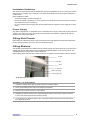
Ventilation
For efficient operation of the chiller, it is essential that adequate ventilation be provided around the
refrigeration unit. The two sides require a clearance of 50 mm. Additionally, one of the doors may be placed
against a wall so long as a clearance of 50 mm is left. A clearance of 200 mm is required above the cabinet.
Important
For efficient operation of the chiller, it is essential that adequate ventilation be
provided around the refrigeration unit.

5
SKOPE SL295
Installation
User Manual
Installation Guidelines
The maximum recommended ambient temperature (at place of installation) is 40°C for swing door models
(SW) and 32°C for sliding door models (SL). This chiller will generally use less power when installed in a
cooler location.
When installing the chiller:
• Avoid direct sunlight and warm draughts etc.
• Ensure the cabinet is positioned on a level surface so the doors shut and seal correctly and to prevent
the condensate tray from overflowing.
• Do not overload the power supply (see the rating label inside the cabinet for power supply and current
draw).
Power Supply
The chiller is supplied with a 1.8m flexible power cord fitted with a 3-pin plug, which exits out the side of the
cabinet at floor level. The power cord should be retrieved before the cabinet is positioned, as wall and
partitions may make access difficult.
Fitting Kick Panels
Before fitting the cabinet kick panels, remove and discard the transit bracket locating the unit lifting arms.
Ensure all three unit lifting arms are in the vertical (upright) position.
Fitting Shelves
The SKOPE SL295 Speed Lane Chiller has three cabinet shelves. The narrow shelf sits on the floor of the
cabinet while the two wider shelves may be positioned at different heights to suit various products. The
adjustable shelves are held in place with four shelf clips.
Merchandising ticket strips are also provided, which can be clipped to the front edges of all three shelves.
Procedure 1: To fit the shelves
1. Unpack the shelves, shelf clips and ticket strips from inside the cabinet.
2. Fit the merchandising ticket strips to the shelves (as required).
3. Place the narrow shelf on the floor of the cabinet.
4. Establish the desired position for the adjustable height shelves and securely engage a shelf clip
in each of the shelf support strips (see image above)
5. .Fit the shelves onto the shelf support clips, ensuring the shelf locating tags are facing the side of
the cabinet with air slots.
Shelf with ticket strip fitted
Shelf support strip
Shelf clip
Shelf
Ticket strip
Shelf locating tags
Air slots

6Operation
User Manual
SKOPE SL295
2 Operation
Loading
When loading the cabinet shelves with product:
• Ensure the shelves are securely fitted.
• Allow air space around all packages for even cooling and efficient operation of the chiller.
• Leave an airspace of at least 75 mm (3”) above packages on the top shelf.
• Do not allow products to hang over the front of the shelf as this could prevent the door from shutting or
cause glass breakage.
Operating the Cabinet
Plug in the cabinet and check operation of the refrigeration unit, electronic controller and cabinet interior
lights.
Refrigeration Cartridge
The compressor and evaporator and condenser fans should all operate initially. You can confirm this by
listening for compressor switch on and checking for air circulation inside the cabinet and airflow up the front
of the doors.
The compressor should switch off when the cabinet internal air temperature reaches approximately +2°C and
on again at approximately +4°C. The internal cabinet air will continue to circulate at all times. The condenser
fan runs continuously to circulate air up the front of the doors and the evaporator fan runs continuously to
provide internal air circulation.
Electronic Controller
The electronic controller will either display the internal cabinet temperature or the controller setpoint. The
compressor “on” icon will indicate that the compressor is operating (see “Controller Display” on page 10).
Cabinet Interior Lights
The cabinet interior lights are initially on, and will stay on permanently while the cabinet is connected to the
power supply. The cabinet lighting will require a period of time to stabilise following initial start up.

7
SKOPE SL295
Electronic Controller
User Manual
3 Electronic Controller
Overview
Depending on the date of manufacture, the cabinet will be fitted with a SKOPE customised CAREL ir33
controller (before September 2022) or a SKOPE customised CAREL S4 EVO controller (after September
2022). Check the label on top of the controller to verify the controller type.
To ensure efficient operation, the electronic controller forces regular defrosts. During the defrost cycle, the
compressor and condenser fan switch off and the evaporator fan stays on.
CAREL S4 EVO
Overview
The CAREL S4 EVO electronic controller is visible through a cut-out in the cabinet’s front panel. The
electronic controller is pre-programmed and requires no initial set-up or additional programming. SKOPE
does not recommend that the settings be changed unless absolutely necessary.
To achieve energy efficient operation, the electronic controller uses temperature probes to control and display
the cabinet’s temperature, collect data, indicate temperature alarms, and force a defrost cycle when required.
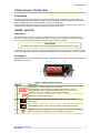
Faceplate
Because the electronic controller plays such an important role, it’s helpful to know the parts of the
faceplate you may use.
CAUTION
The electronic controller must only be adjusted by an authorised service agent.
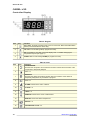
Table 1: CAREL S4 EVO faceplate
No. Item Description
1
Digital display of cabinet temperature or messages.
The temperature is what the sensor inside the cabinet detects, and not
necessarily the product temperature. However, they may be very close,
depending on how the controller is set to sense temperature.
2Up: Button. Used for programming.
3Mute (set): Button. Press to mute the alarm. Press and hold to access
parameters.
4Light (down): Button. Press to switch the cabinet interior light on and off.
5Defrost: Indicator. On when the defrost is activated. Flashes when activating the
defrost is temporarily delayed due to other procedures in progress.
ES
12
3
4
5
68
7

8Electronic Controller
User Manual
SKOPE SL295
Lights
Press the Light button on the electronic controller faceplate to manually switch the cabinet light on and off.
Temperature Setpoint
The temperature setpoint is set at the factory to 2.0°C, and can be adjusted between 1.0°C and 3.5°C for
other specialist applications if required.
SKOPE does not recommend changing the setpoint unless it is absolutely necessary, and then only by small
increments at a time.
Messages and Alarms
The following tables explains the messages and alarms that the electronic controller displays.
6Compressor: Indicator. On when the compressor and condenser fan starts.
Flashes when activating the compressor is temporarily delayed.
7Fan: Indicator. On when the internal cabinet fans are activated. Flashes when
activating the fans is temporarily delayed.
8Alarm: Indicator. On when the alarm is signalled.
Procedure 2: To view and adjust the temperature setpoint for the CAREL S4 EVO
1. Press and hold the set button for 3 seconds until PS is shown on the
display, indicating entry into the controller settings menu.
2. Press the up or down button to scroll through the menu until St is shown on
the display.
3. Press the set button.
The current setpoint value shows on the display.
4. Press the up or down button to increase or decease the setpoint value to the required
temperature.
5. Press the set button to temporarily save the setpoint value.
6. Press and hold the set button for 3 seconds to permanently save the setpoint value and exit the
controller settings menu.
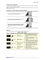
Table 2: CAREL S4 EVO messages
Display Description
The cabinet is in “Normal” mode and the electronic controller displays the temperature.
The cabinet’s internal temperature is above 13°C.
The cabinet is in cold climate protection (CCP) mode. The cabinet enters CCP mode if
the room’s ambient temperature gets too cold. The lights remain on and cannot be
switched off.
Table 1: CAREL S4 EVO faceplate (continued)
No. Item Description

9
SKOPE SL295
Electronic Controller
User Manual
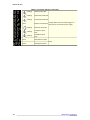
Table 3: CAREL S4 EVO alarms
Display Description
Probe fault. An alarm sounds. Contact a service agent.
Low temperature alarm. An alarm sounds. The temperature inside the cabinet is too cold.
The controller will automatically reset the alarm once the temperature inside the cabinet
rises.
High temperature alarm. An alarm sounds. The temperature inside the cabinet is too
warm. The controller will automatically reset the alarm once the temperature inside the
cabinet drops.
Refrigeration system high
temperature
Pre-warning (auto reset)
1. Check the cabinet’s ventilation and ensure
that it is installed in a suitable environment
(see page 4).
2. To reset the “CHt” alarm, unplug the cabinet
from the power supply for 1 minute, then
reconnect to power supply.
3. If the alarm persists, contact a service agent.
Refrigeration system high
temperature
Shutdown (manual reset)
Low voltage alarm. An alarm sounds. The mains voltage is low. The controller switches
off the compressor. The controller will automatically reset the alarm once the mains
voltage rises.
High voltage alarm. An alarm sounds. The mains voltage is high. The controller switches
off the compressor. The controller will automatically reset the alarm once the mains
voltage drops.
Electronic controller fault. Contact a service agent.

10 Electronic Controller
User Manual
SKOPE SL295
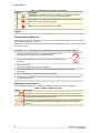
CAREL ir33
Controller Display
Table 4: Keypad
Item Key Function
1Prg / mute: To initiate programme sets, press for 5 seconds. Mutes the audible alarm
(buzzer) and deactivates the alarm relay.
2UP / aux: To scroll settings UP (in programme mode).
3Set: If pressed for more than 2 seconds displays and / or enables changing the
temperature setpoint (see page 11).
4DOWN / def: To scroll settings DOWN (in programme mode).
Table 5: Icons
Item Icon Function
5
COMPRESSOR:
ON when the compressor and condenser fan starts. Flashes when activation of the
compressor is temporarily delayed.
6FAN: n.a.
7
DEFROST:
ON when the defrost is activated. Flashes when the activation of the defrost is
temporarily delayed due to procedures in progress.
8AUX: n.a.
9ALARM: Flashes in the event of alarms.
10 CLOCK: n.a.
11 LIGHT: n.a.
12 SERVICE: Flashes in the event of malfunctions.
13 DISPLAY: Shows the cabinet temperature.
14 HACCP: n.a.
15 CONTINUOUS CYCLE: n.a.

11
SKOPE SL295
Electronic Controller
User Manual
Temperature Setpoint
The chiller temperature setpoint is factory set at 2.0°C. If necessary the standard setting can be adjusted
between 1°C and 3.5°C (see Table 3 below).
SKOPE do not recommend that the setpoint be changed unless it is absolutely necessary, and then only by
small increments at a time.
Alarms
The following table explains the alarms that the electronic controller displays.
Procedure 3: To view and adjust the temperature setpoint
1. To view the setpoint: press and hold the SET key for 2
seconds, until the setpoint value flashes.
2. To adjust the setpoint: press either the UP or DOWN
keys to display the required setpoint value.
3. Press the SET key again to memorise the new setpoint
value. If this is not done within 60 seconds, changes
will be lost and you will need to repeat the above
procedure.
Table 6: Controller Alarms
Code Display Icon Alarm Description Action
Flashing Product HIGH
temperature alarm
1. Check the cabinet product loading to
ensure ventilation slots are not blocked
and that product does not overhang the
shelves.
2. Ensure the cabinet is installed with good
refrigeration unit ventilation.
3. Check and clean the condenser coil (see
page 15).
4. Unplug cabinet from the power supply for
1 minute, then reconnect to power supply.
Flashing Product LOW
temperature alarm
Flashing Refrigeration system
high temperature
pre-warning
1. Clean the condenser coil (see page 15).
2. Check refrigeration ventilation. Ensure
clear airpath at the top and front of the
cabinet (to extract hot air). A minimum of
200mm clear space is required in front of
the refrigeration unit.
3. Ensure the cabinet is installed in a
suitable environment.
4. Unplug cabinet from the power supply for
1 minute, then reconnect to power supply.
Flashing
Refrigeration system
high temperature
shutdown

12 Electronic Controller
User Manual
SKOPE SL295
Flashing Ambient probe fault
Unplug cabinet from the power supply for 1
minute, then reconnect to power supply.
Flashing Evaporator probe fault
Flashing Condenser probe fault
None Defrost over-time limit
Flashing Real-time clock fault
Flashing Controller E prom
error
Flashing Controller E prom
error
None Start defrost request
None
None End defrost request
Table 6: Controller Alarms (continued)

13
SKOPE SL295
Servicing
User Manual
4 Servicing
Cleaning
When necessary, wipe both the interior and exterior of the cabinet with a damp cloth. Ensure the chiller is
disconnected from the mains power supply before cleaning the cabinet.
To ensure the sliding doors open and close smoothly, the door rollers and the sliding door tracks should be
kept clear of any dirt build-up.
The condenser coil and optional air filter MUST be cleaned regularly.
Table 7: Troubleshooting
Problem Possible cause Repair
Cabinet not operating and no
controller display:
• Loss of power supply. • Check mains power supply.
Cabinet lights not operating:
• Blown cabinet fuse. • Requires technical repair by a SKOPE
Authorised Service Agent.
• Failed fluorescent tube. • Check fluorescent tubes.
• Controller alarm. • Determine cause and eliminate (see
pages 12-13).
Power consumption is higher
than expected:
• Unit operating too hot. • Clean condenser. Ensure the chiller is
installed with good ventilation around
the refrigeration unit.
• Cabinet door is opened
excessively.
• Keep door/s open for minimum time.
Product is too warm and
spoiling:
• Restricted cabinet airflow. • Ensure product is not blocking airflow
slots and there is air space around all
the product.
• Temperature setpoint is too
warm.
• Adjust setpoint (see page 10).
Warm cabinet temperatures
and/or compressor operating
for long periods (more than 1
hour):
• Blocked condenser. • Clean condenser (see page 15).
• Poor refrigeration unit
ventilation.
• Ensure the cabinet is installed with
good ventilation around the
refrigeration unit.
Caution
Disconnect the cabinet from the mains power supply before any cleaning, or attempting
maintenance.
Warning
If the electronic controller display flashes “cht” clean the condenser coil immediately.
Sliding door tracks
Sliding door Door outer frame

14 Servicing
User Manual
SKOPE SL295
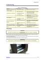
Condenser Coil and Optional Air Filter
The condenser coil and optional air filter are located behind the condenser grille on the side of the cabinet.
The condenser coil and optional air filter must be kept clean for efficient and reliable operation. To ensure
trouble-free performance, SKOPE recommends isolating the cabinet from the mains power supply every two
months and vacuum cleaning the dust and fluff from the condenser coil and air filter.
If the electronic controller display flashes ‘cht’ the condenser coil needs cleaning immediately.
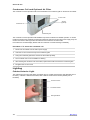
Lighting
Cabinet Interior Light
The cabinet has four interior side lights, each fitted with one 18 Watt T8 fluorescent tube (SKOPE part no.
ELL6267) - OSRAM L 18W/840 Cool White, Ø26 x 588mm and fluorescent starter (SKOPE part no.
ELZ2840).
Procedure 4: To access the condenser coil
1. Disconnect the cabinet from the mains power supply.
2. Undo the 1/4 turn screw at the top of the condenser grille.
3. Swing the condenser grille down and remove the air filter (if fitted).
4. The condenser coil is now accessible for cleaning.
5. After cleaning the condenser coil and air filter, replace the air filter and close the condenser grille.
6. Re-tighten the 1/4 turn screw.
Air filter
(optional)
Condenser coil
Condenser grille
1/4 turn screw
Side light diffuser
Fluorescent starter
Fluorescent tube

15
SKOPE SL295
Servicing
User Manual
Warranty
To receive a warranty for your purchased cabinet, you MUST register your cabinet within four weeks from the
date of invoice either by:
• filling out the in-cabinet warranty form and posting or faxing it back to SKOPE
• or filling out the online warranty form.
Cabinets that are not registered within the four weeks are not eligible for a warranty.
Procedure 5: To replace the fluorescent tube or starter
1. Disconnect the cabinet from the mains power supply.
2. Remove the side light diffuser, by compressing the back section of the diffuser until it disengages
from the aluminium housing and then push the diffuser back (see Figure 5 below).
3. The fluorescent tube and starter can now be removed. Revolve the tube until the pin position
allows withdrawal.
4. When refitting the diffuser, engage the back section into the housing, and then compress and
snap the front section of diffuser back into place working down the full length of the light.

SKOPE Contacts
SKOPE Industries Limited
ABN: 73 374 418 306
AU: 1800 121 535
NZ: 0800 947 5673
www.skope.com
-
 1
1
-
 2
2
-
 3
3
-
 4
4
-
 5
5
-
 6
6
-
 7
7
-
 8
8
-
 9
9
-
 10
10
-
 11
11
-
 12
12
-
 13
13
-
 14
14
-
 15
15
-
 16
16


Skope SL295 Speed Lane Chiller User manual
- Type
- User manual
Ask a question and I''ll find the answer in the document
Finding information in a document is now easier with AI
Related papers
-
Skope SKT500X User manual
-
-
-
-
-
-
-
-
-
Other documents
-
scope Centaur BC090-CS User manual
-
 In-Lite SMART EVO FLEX User manual
-
Serene SC112G User manual
-
Lindab CCP User manual
-
Serene HB80-2 User manual
-
-
-
Haier SC-650 Installation And Operating Instructions Manual
-
-
