Page is loading ...

DeZURIK, Inc. Sartell, Minnesota USA | Phone: 320-259-2000 | www.dezurik.com | [email protected]
WILLAMETTE AWWA METAL
SEATED BALL VALVES
Instruction D12001
January 2022

DeZURIK
Instruction and Operating Manual Page 2 © 2022 DeZURIK, Inc.
Instructions
These instructions are for use by personnel who are responsible for the installation, operation and
maintenance of DeZURIK valves, actuators or accessories.
Safety Messages
All safety messages in the instructions are identified by a general warning sign and the signal word CAUTION,
WARNING or DANGER. These messages indicate procedures to avoid injury or death.
Safety label(s) on the product indicate hazards that can cause injury or death. If a safety label becomes difficult
to see or read, or if a label has been removed, please contact DeZURIK for replacement label(s).
Personnel involved in the installation or maintenance of valves should be constantly alert to potential
emission of pipeline material and take appropriate safety precautions. Always wear suitable protection
when dealing with hazardous pipeline materials. Handle valves which have been removed from service
with suitable protection for any potential pipeline material in the valve.
Inspection
Your DeZURIK product has been packaged to provide protection during shipment; however, items can be
damaged in transport. Carefully inspect the unit for damage upon arrival and file a claim with the carrier if
damage is apparent.
Parts
Replaceable wear parts are listed on the assembly drawing. These parts can be stocked to minimize
downtime. Order parts from your local DeZURIK sales representative or directly from DeZURIK. When ordering
parts please provide the following information:
If the valve has a data plate: please include the 7-digit part number with either 4-digit revision number
(example: 9999999R000) or 8-digit serial number (example: S1900001) whichever is applicable. The
data plate will be attached to the valve assembly. Also, include the part name, the assembly drawing
number, the balloon number and the quantity stated on the assembly drawing.
If there isn't any data plate visible on the valve: please include valve model number, part name, and
item number from the assembly drawing. You may contact your local DeZURIK Representative to help
you identify your valve.
DeZURIK Service
DeZURIK service personnel are available to maintain and repair all DeZURIK products. DeZURIK also offers
customized training programs and consultation services. For more information, contact your local DeZURIK
sales representative or visit our website at DeZURIK.com.

DeZURIK
Willamette AWWA Metal Seated Ball Valve
January 2022 Page 3 D12001
Table of Contents
Description ........................................................................................................................................................ 4
General .......................................................................................................................................................... 4
Body .............................................................................................................................................................. 4
Ball ................................................................................................................................................................ 4
Torque Unit (Valve Operating Mechanism) .................................................................................................... 4
Handling and Storage ........................................................................................................................................ 4
Installation ......................................................................................................................................................... 5
Fusion/Powder Coated Valves ........................................................................................................................... 5
Maintenance and Operation .............................................................................................................................. 6
Operator ........................................................................................................................................................ 6
Basic Valve and Torque Unit ......................................................................................................................... 6
Shaft Seal Replacement (Closed Position) .................................................................................................... 6
Shaft Seal Replacement (Open Position) ....................................................................................................... 7
Lubrication ......................................................................................................................................................... 9
General ........................................................................................................................................................ 12
Ball Valve .................................................................................................................................................... 12
Torque Unit .................................................................................................................................................. 12
Power Supply for Operating Valves ................................................................................................................. 13
Troubleshooting ............................................................................................................................................... 14

DeZURIK
Willamette AWWA Metal Seated Ball Valve
January 2022 Page 4 D12001
Description
General
DeZURIK’s Willamette AWWA Metal Seated Ball Valve (VBL) is a ball type, quarter-turn valve with a full-ported
circular waterway through the body and ball in the open position. Each ball valve typically consists of four (4)
main elements: a pressure vessel (body), a rotatable closing element (ball), a torque unit, and an operator. The
"standard" material of construction for the body is ductile iron; standard ball materials are ductile iron, carbon
steel or 316 stainless steel. Ball valve construction is in complete accordance with AWWA Standard C507 for
Ball Valves 6 In Through 60 In.
Body
The standard body has ASME B16.42 Class125/150 or Class 250/300 flanges and houses the ball. The body
has integrally cast trunnions and provides rigid means for supporting the torque unit (without the necessity of
additional supports). There are two (2) pipe connections, one for an air vent and the other for drain. The body
has rigidly attached corrosion resistant metal seat(s).
Ball
The ball has bronze-bushed trunnions. An extension of one trunnion, called the operating shaft, passes
through a sealing device (o-ring retainer) and connects to the torque unit. The operating shaft is stainless steel
or chrome plated carbon steel. The sealing device is capable of being removed and having its seals replaced
without removing the valve from the line.
The ball has corrosion resistant metal seat(s) rigidly attached and fully adjustable to provide tight sealing in
accordance with AWWA standard C507 in one direction or both directions, as an option. The ball shaft is
designed for a factor of safety for all combined stresses of at least five to one.
Torque Unit (Valve Operating Mechanism)
The torque unit employs a traveling crosshead to impart positive rotary movement to the ball by means of a link
and lever connected to the ball shaft. A ball shaft support bearing is supplied on the cover. The torque unit is
designed such that during the first 50 percent of stroke in closing, the flow area is reduced by approximately 81
percent. The remaining flow area is gradually reduced to a complete shutoff throughout the last 50 percent of
closing stroke. Likewise, when opening, the first 50 percent of the stroke gradually opens the first 19 percent.
The last half of the stroke opens the valve completely. All materials of the torque unit subject to rubbing are of
different hardness. The torque unit is capable of being inspected, lubricated, removed and repaired without
removing the valve from the pipeline.
Handling and Storage
Lifting the valve improperly may damage it. Do not fasten lifting devices to the actuator, ball or through the seat
opening in the body. Lift the valve with slings, chains or cables fastened around the valve body, or fastened to
bolts or rods through bolt holes in the flanges.
If installation will be delayed, place valve indoors in secure, weather tight storage. If temporary outside storage
is unavoidable, make sure a vermin proof rain cover (water shedding tarp, etc.) is secured around/over the
equipment to keep off rain and mud. Skid and set the assembly on a flat, solid, and well drained surface for
protection from ground moisture, runoff and pooled rain water.

DeZURIK
Willamette AWWA Metal Seated Ball Valve
January 2022 Page 5 D12001
Installation
• Before installation, remove foreign material such as weld spatter, oil, grease, and dirt from the pipeline.
• Prepare pipe ends and install valves in accordance with the pipe manufacturer’s instructions for the
joint used.
Do not deflect the pipe-valve joint. Minimize bending stresses in the valve end
connection with pipe loading.
If excessive seat leakage occurs during start-up, recheck the installation and
eliminate any distortion to the valve body.
• Ensure the valve and pipeline flanges are concentric to ensure proper flange sealing and seat leakage
control.
• Tighten the flange bolts or studs in a crisscross pattern and minimum of four stages.
• Do not anchor support legs or pads of the valve. The integral valve supports are intended to support the
weight of the valve and actuator only. The connecting piping must be self-supporting and a flexible
connector be installed on the valve’s seat side.
• Single-seated valves will have an arrow indicating the direction of flow. The direction of flow refers to
the flow coming from the pump.
• Pump control is the primary use of single-seated VBL and the seat is always on the pump side of the
valve. When the pump is off, there is low or zero pressure on the pump side of the valve. At the same
time, there is full pressure on the system side. The system pressure holds the ball tight against the seat
to prevent backflow. The valve does not operate when the pump is turned off and there is system
pressure. When the pump turns on, it generates pressure higher than the system pressure, causing
enough differential pressure to unseat the ball and the valve can begin opening.
• Properly adjusted pump control valves will close while the pump is still running and creating pressure.
There is always pressure from the pump pushing the ball away from the seat. When the valve finally
closes, then the pump turns off. The system pressure takes over and holds the ball tight against the
seat.
Fusion/Powder Coated Valves
Valves with fusion/powder coated exterior paint require flat washers to be installed
under the flange nuts when installing the valve to the pipeline flange to prevent the
paint from cracking or chipping.

DeZURIK
Willamette AWWA Metal Seated Ball Valve
January 2022 Page 6 D12001
Maintenance and Operation
All valves should be stored in the open position and should remain open until they are installed in the line. The
valve should only be opened or closed using the supplied actuator. Do not use any other manual or
mechanical means to open or close the valve. If the ball does not rotate freely – see troubleshooting
section. When the valve is bolted into the line, the bolts should be retightened after the first week of service.
Periodically check tightness of the bolts connecting the operator support brackets to the valve body.
Operator
All bearings and moving parts are carefully lubricated during assembly and should give years of trouble-free
operation without further maintenance under normal service conditions.
Basic Valve and Torque Unit
The basic ball valve is equipped with water lubricated trunnion bearings and requires no maintenance. The
torque unit is lubricated at assembly and should give years of trouble-free operation under normal service
conditions.
Shaft Seal Replacement (Closed Position)
See figure 1 and table 1 for basic valve assembly component identification. See figure 2 and table 2 for
basic torque unit component identification.
The operating shaft of the valve is equipped with o-ring seals. The O-Rings may be replaced while the valve is
installed. The procedure for replacing rings with the valve in the closed position is as follows:
Servicing the valve while the pipeline is under pressure can cause personal injury or
equipment damage. Relieve pipeline pressure before servicing the valve.
1. Relieve the pressure in the pipeline and close the valve.
2. Drain oil, if any, from the torque unit housing (B02) and remove indicator (B11) and cover (B01).
3. Tighten the plug adjusting set screw (A16) by turning it ½ turn maximum, pushing the ball (A05) against
the thrust washers (A13). This accomplishes two things: it seals leakage and it locks the ball in position
4. Remove link pin (B19).
5. Run crosshead (B15) to top of stroke in order to get links (B14) out of the way.
Accidental operation of power actuator can cause personal injury or equipment
damage. Disconnect and lock out power to actuator before servicing.
6. If the actuator is powered, disconnect and lock out the pneumatic, hydraulic, or electrical power to
prevent accidental operation of the actuator.
7. Loosen clamp bolts (B24) in lever (B20) and remove lever (B20) from operating shaft (A06). Carefully
de-burr sharp edges of dowel pin hole in shaft (A06) and all other surfaces over which o-rings will pass
during disassembly and assembly.

DeZURIK
Willamette AWWA Metal Seated Ball Valve
January 2022 Page 7 D12001
Maintenance and Operation (Continued)
8. Remove retaining ring (A21) from housing and retract o-ring retainer (A14).
9. Install new o-rings (A26, A27), re-insert o-ring retainer (A14) and retaining ring (A21) and re-install lever
(B20).
10. After lever (B20) is reinstalled, connect power to the actuator, and run crosshead (B15) back to closed
position. Make sure all mechanisms are in proper alignment.
11. Replace link pin cotters (if used) and be sure to bend over ends of pin.
12. Release adjusting screw (A16) just enough so the ball can turn freely and retighten sealing and locknut
(A29) on plug adjusting screw (A16).
Shaft Seal Replacement (Open Position)
See figure 1 and table 1 for basic valve assembly component identification. See figure 2 and table 2 for
basic torque unit component identification.
The valve can be packed in the open position using the following procedure:
Servicing the valve while the pipeline is under pressure can cause personal injury or
equipment damage. Relieve pipeline pressure before servicing the valve.
1. Relieve the pressure in the pipeline.
2. Drain oil, if any, from the torque unit housing (B02) and remove indicator (B11) and cover (B01).
3. Tighten up the plug adjusting screw (A16) by turning it ½ turn maximum, pushing the ball (A05) against
the thrust washers (A13).
4. Loosen the clamp bolts (B24) in lever (B20) and remove key, or dowel (B23).
5. Run crosshead (B15) down to closed position.
6. Remove link pin (B19).
7. Run crosshead (B15) back to top of stroke in order to get links (B14) out of way.
Accidental operation of power actuator can cause personal injury or equipment
damage. Disconnect and lock out power to actuator before servicing.
8. If the actuator is powered, disconnect and lock out the pneumatic, hydraulic, or electrical power to
prevent accidental operation of the actuator.
9. Remove lever (B20) from operating shaft (A06). Carefully de-burr sharp edges of dowel pin hole in
shaft (A06) and all other surfaces over which o-rings will pass during assembly and disassembly.
10. Remove retaining ring (A21) and o-ring retainer (A14) and install new o-rings (A26, A27) using same
procedure as described in Shaft Seal Replacement (Closed Position).
11. Re-install lever (B20), connect power to the actuator, run crosshead (B15) back to closed position and
reconnect links (B14). Replace link pin cotter (if used) and be sure to bend over ends of pin.

DeZURIK
Willamette AWWA Metal Seated Ball Valve
January 2022 Page 8 D12001
Maintenance and Operation (Continued)
12. Run complete operating mechanism to open position, rekey and tighten clamp bolts (B24) on lever
(B20). Make sure all operating mechanisms are properly aligned.
13. Release adjusting screw (A16) just enough so that ball (B05) can turn freely and retighten sealing and
locknut (A29) on plug adjusting screw (A16).

DeZURIK
Willamette AWWA Metal Seated Ball Valve
January 2022 Page 9 D12001
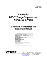
Figure 1: Basic Valve Assembly

DeZURIK
Willamette AWWA Metal Seated Ball Valve
January 2022 Page 10 D12001
Table 1: Basic Valve Assembly Components
A01
BODY HALF (OPERATOR END)
A02
BODY HALF (TRUNNION END)
A03
ADAPTOR (WITH SEAT)
A04
ADAPTOR (WITHOUT SEAT)
A05
BALL
A06
SHAFT
A07
SEAT RING
A08
BODY BUSHING
A09
BALL JOURNAL
A10
TAPER PIN
A11
DOWEL PIN
A12
DOWEL PIN
A13
THRUST WASHER
A14
O-RING RETAINER
A15
THRUST PIN
A16
SET SCREW
A17
SET SCREW
A18
STUD
A19
NUT
A20
PIPE PLUG
A21
RETAINING RING
A22
SCREW
A23
O-RING (ADAPTOR)
A24
O-RING (BODY HALF)
A25
O-RING (THRUST PIN)
A26
O-RING (O-RING RETAINER, INSIDE)
A27
O-RING (O-RING RETAINER, OUTSIDE)
A28
O-RING (SEAT RING)
A29
JAM NUT
A30
STUD
A31
NUT
A32
LUBE FITTING
A33
EYE BOLT
A34
JAM NUT
A35
PIPE PLUG
A36
DATA PLATE
A37
DRIVE SCREW
A38
SEAT SIDE TAG
A39
DRIVE SCREW
A41
BUSHING

DeZURIK
Willamette AWWA Metal Seated Ball Valve
January 2022 Page 11 D12001
Figure 2: Torque Unit Assembly
Table 2: Torque Unit Assembly Components
B01
COVER
B16
BUSHING
B02
HOUSING
B17
RETAINING RING
B03
PIN
B18
SIDE MEMBER
B04
NUT
B19
LINK PIN
B05
LOCKWASHER
B20
LEVER
B06
SCREW
B21
SET SCREW
B07
SCREW
B22
NUT
B08
LOCKWASHER
B23
PIN
B09
PIN
B24
SCREW
B10
INDICATOR SHAFT
B25
NUT
B11
INDICATOR
B26
LOCKWASHER
B12
SET SCREW
B27
BUSHING
B13
BUSHING
B28
VENT PLUG
B14
LINK
B29
SET SCREW
B15
CROSSHEAD

DeZURIK
Willamette AWWA Metal Seated Ball Valve
January 2022 Page 12 D12001
Lubrication
General
Trunnion bronze bushings receive a significant amount of water lubrication from the media itself. For those ball
valves equipped with grease fitting lubrication points on the body assembly – each lubrication point should be
greased with a hand-pump gun (Caution! do not use air-operated grease guns). Use one of the approved
lubricants from Table A.
Table A: Approved Lubricants
Manufacturer
Type
NSF Approved
DowDupont
Molykote 111
Yes
Mobil
Mobilgrease FM221
No
Fiske Brothers
Lubriplate #110
No
Fiske Brothers
Lubriplate # 130A
No
Richfield
Rocolub # 1
No
Shell
Alvania #1
No
Texaco
Marfak # 1
No
Stewart Warner Co.
Alernite Temprite #1
No
Standard Oil Co., (Ind)
Stanolith Grease #42
No
Ball Valve
Lubricate twice annually (more often if valve is operated frequently or in harsh service conditions) using one of
the approved lubricants from Table A. Use approximately 4 ounces of grease per bushing per re-lubrication
event. Check with the factory in the event that a special application prevents the use of the approved
lubricants.
Torque Unit
Lubricate twice annually (more often if valve is operated frequently) or any time the cover is removed. Wipe out
old lubricant and replace with new lubricant using one of the lubricants from Table A. Spread lubricant on the
crosshead side members; crosshead guides, leadscrews, all rotating and sliding areas, bearings, exposed
steel or cast iron machined parts, etc. See Table B for recommended amount of lubricant for the various size
units.
Table B: Torque Unit Lubrication Requirements
Unit Size
Amount of Lubricant (lbs.)
T-3000
2 ½
T-2000 & T-1100
2
T-578 & T-315
1 ½
T-176, T-70 & T-22
1

DeZURIK
Willamette AWWA Metal Seated Ball Valve
January 2022 Page 13 D12001
Lubrication (Continued)
If a hydraulic cylinder is provided, Table C shows the recommended hydraulic fluids.
Table C: Hydraulic Fluids
Manufacturer
Hydraulic Fluid
Atlantic-Richfied Co.
Duro AWS-150
Shell
Tellus #32
Standard of California
Chevron EP-9
Texaco
Rando HD-A
Mobil
DTE 24
Castrol
Hyspin AW32
Power Supply for Operating Valves
It is essential that a continuous and reliable source of power (whether it be liquid, gas or electrical) be provided
for operating the valve. The line which conveys the power to the controls must be of ample size so that
sufficient pressure and volume can be delivered directly to the power port of the controls. The differential
pressure between the top and bottom of the piston in the actuating cylinder causes the piston rod to move. It is
essential that both the power and exhaust line be of ample size to provide adequate speed.
The power source must be suitable for cylinder use. Use of a filter or strainer where needed is recommended.
In the case of air, a continuous and reliable source of filtered air is required to operate the cylinder. The air
should be clean and reasonably dry (free from moisture). A lubricator may be used, if desired for maximum
cylinder life. Locate the lubricator as close to the control supply port as practical. Avoid excessive oil flow
settings which flood the components with oil. Reduce settings if oil coalesces (form pools in the bottom of the
lines) or drips from the exhaust port. Carefully evaluate the need for lubrication prior to installing a lubricator.
Most valve installations do not require an exceptional number of cylinder cycles and the factory pre-lubrication
will provide years of service without a lubricator.
Many valve positioners, transducers, and other special controls require that
instrument quality, dry, oil free air is used. Check all special controls for compatibility
with lubricated air prior to its use.

DeZURIK
Willamette AWWA Metal Seated Ball Valve
January 2022 Page 14 D12001
Troubleshooting
Condition
Possible Cause
Corrective Action
Shaft seal leaks.
O-ring is worn.
Replace o-ring.
Valve leaks excessively from
one side of the ball to the other.
Foreign matter caught between
seats
Fully open valve to remove
object.
Closed position stop is set
incorrectly.
Adjust closed position stop.
Valve body is distorted.
Remove stress to valve body.
Loss of media’s seating
pressure.
Apply media pressure.
Seat is worn or damaged.
Repair seat or replace valve.
Valve leaks at flange joint.
Loose flange bolting.
Tighten flange bolting.
Blown flange gasket.
Replace flange gasket.
Misalignment or damage to field
piping and supports.
Adjust misalignment or repair
piping or supports.
Damaged flange face/s or
improper flange connections.
Repair flange, replace valve
body or adjust flange
connections.
Valve does not fully close.
Object is wedged between seat
and ball.
Fully open valve to remove
object.
Closed position stop is not set
correctly.
Adjust closed position stop.
Valve does not fully open.
Open position stop is not
adjusted correctly.
Adjust open position stop.
Valve fails to operate from open
to close position or from closed
to open.
Object is wedged between seat
and ball.
Fully open or close valve to
remove object.
Torque unit low on lubricant.
Add lubricant.
Torque unit component failure.
Repair or replace torque unit.
Actuator component failure.
Repair or replace actuator.

Limited Warranty
DeZURIK, Inc. (“Seller”) manufactured products, auxiliaries and parts thereof that we manufacture for a period of twenty-four (24) months from date
of shipment from Seller’s factory, are warranted to the original purchaser only against defective workmanship and material, but only if properly stored,
installed, operated, and serviced in accordance with Seller’s recommendations and instructions.
For items proven to be defective within the warranty period, your exclusive remedy under this limited warranty is repair or replacement of the defective
item, at Seller’s option, FCA Incoterms 2020 Seller’s facility with removal, transportation, and installation at your cost.
Products or parts manufactured by others but furnished by Seller are not covered by this limited warranty. Seller may provide repair or replacement
for other’s products or parts only to the extent provided in and honored by the original manufacturer’s warranty to Seller, in each case subject to the
limitations contained in the original manufacturer’s warranty.
No claim for transportation, labor, or special or consequential damages or any other loss, cost or damage is being provided in this limited warranty.
You shall be solely responsible for determining suitability for use and in no event shall Seller be liable in this respect.
This limited warranty does not warrant that any Seller product or part is resistant to corrosion, erosion, abrasion or other sources of failure, nor does
Seller warrant a minimum length of service.
Your failure to give written notice to us of any alleged defect under this warranty within twenty (20) days of its discovery, or attempts by someone other
than Seller or its authorized representatives to remedy the alleged defects therein, or failure to return product or parts for repair or replacement as
herein provided, or failure to store, install, or operate said products and parts according to the recommendations and instructions furnished by Seller
shall be a waiver by you of all rights under this limited warranty.
This limited warranty is voided by any misuse, modification, abuse or alteration of Seller’s product or part, accident, fire, flood or other Act of God, or
your failure to pay entire contract price when due.
The foregoing limited warranty shall be null and void if, after shipment from our factory, the item is modified in any way or a component of another
manufacturer, such as but not limited to; an actuator is attached to the item by anyone other than a Seller factory authorized service personnel.
All orders accepted shall be deemed accepted subject to this limited warranty, which shall be exclusive of any other or previous warranty, and this
shall be the only effective guarantee or warranty binding on Seller, despite anything to the contrary contained in the purchase order or represented by
any agent or employee of Seller in writing or otherwise, notwithstanding, including but not limited to implied warranties.
THE FOREGOING REPAIR AND REPLACEMENT LIMITED WARRANTY IS IN LIEU OF ALL OTHER WARRANTIES, OBLIGATIONS AND
LIABILITIES, INCLUDING, BUT NOT LIMITED TO, ALL WARRANTIES OF FITNESS FOR A PARTICULAR PURPOSE OR OF MERCHANTABILITY
OR OTHERWISE, EXPRESSED OR IMPLIED IN FACT OR BY LAW, AND STATE SELLER’S ENTIRE AND EXCLUSIVE LIABILITY AND YOUR
EXCLUSIVE REMEDY FOR ANY CLAIM IN CONNECTION WITH THE SALE AND FURNISHING OF SERVICES, GOODS OR PARTS, THEIR
DESIGN, SUITABILITY FOR USE, INSTALLATION OR OPERATIONS. NEITHER ANY PERFORMANCE OR OTHER CONDUCT, NOR ANY ORAL
OR WRITTEN INFORMATION, STATEMENT, OR ADVICE PREPARED BY SELLER OR ANY OF OUR EMPLOYEES OR AGENTS WILL CREATE A
WARRANTY, OR IN ANY WAY INCREASE THE SCOPE OR DURATION OF THE LIMITED WARRANTY.
Disclaimer
Metric fasteners should not be used with ASME Class 150/300 bolt holes and flange bolt patterns. If you use metric fasteners with ASME Class 150/300
bolt holes and flange bolt patterns, it may lead to product failure, injury, and loss of life. DeZURIK Inc. disclaims all liability associated with the use of
metric fasteners with ASME Class 150/300 bolt holes and flange patterns, including but not limited to personal injury, loss of life, loss of product,
production time, equipment, property damage, lost profits, consequential damages of any kind and environment damage and/or cleanup. Use of metric
fasteners with ASME Class 150/300 bolt holes and flange bolt patterns is a misuse that voids all warranties and contractual assurances. If you use
metric fasteners with ASME Class 150/300 bolt holes and flange bolt patterns, you do so at your sole risk and any liability associated with such use shall
not be the responsibility of DeZURIK, Inc. In addition to the foregoing, DeZURIK’s Manufacturer’s Conditions apply.
Limitation of Liability
IN NO EVENT SHALL SELLER BE LIABLE FOR ANY DIRECT, INDIRECT, SPECIAL, PUNITIVE, EXEMPLARY, OR CONSEQUENTIAL DAMAGES
(INCLUDING, BUT NOT LIMITED TO; DAMAGE TO OR LOSS OF OTHER PROPERTY OR EQUIPMENT, BUSINESS INTERUPTION, COST OF
SUBSTITUTE PRODUCTS, LOSS OF TIME, LOSS OF PROFITS OR REVENUE, COST OF CAPTIAL, LOSS OF USE, OR DIMINUTION IN VALUE)
WHATSOEVER, AND SELLER’S LIABILITY, UNDER NO CIRCUMSTANCES, WILL EXCEED THE CONTRACT PRICE FOR THE GOODS AND/OR
SERVICES FOR WHICH LIABILITY IS CLAIMED. ANY ACTION FOR BREACH OF CONTRACT BY YOU, OTHER THAN RIGHTS RESPECTING OUR
LIMITED WARRANTY DESCRIBED ABOVE, MUST BE COMMENCED WITHIN 12 MONTHS AFTER THE DATE OF SALE.
Sales and Service
For information about our worldwide locations, approvals, certifications and local representative:
Web site: www.dezurik.com E-Mail: info@dezurik.com
250 Riverside Ave. N., Sartell, MN 56377 ● Phone: 320-259-2000 ● Fax: 320-259-2227
DeZURIK, Inc. reserves the right to incorporate our latest design and material changes without notice or obligation.
Design features, materials of construction and dimensional data, as described in this manual, are provided for your information only
and should not be relied upon unless confirmed in writing by DeZURIK, Inc. Certified drawings are available upon request.
December 2022
/