Page is loading ...

VAR-SOM-MX7 based on NXP/Freescale i.MX7
Evaluation Kit Quick Start Guide
1234567
8
9
11
10 23
13 14 15 16 1712 18 19 20 21
22
24
25
26
27
29
30
28
31
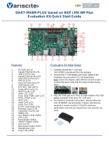
Features:
1. 5V DC In Jack (J25)
2. USB Debug (J23)
3. Gigabit Ethernet #2 (J19)
4. Gigabit Ethernet #1 (J18)
5. USB Host #2 (J22)
6. USB Host #1 (J21)
7. MIPI CSI-2 Camera [optional add-on] (J20)
8. RTC Battery Holder (JBT1)
9. Mini PCI Express Connector (J16)
10. UART3/SAI2 Header (J13)
11. ADC2/SPI Header (J10)
12. LCD/CSI Header (J1)
13. LCD/CSI Header (J2)
14. LCD/CSI Header (J3)
15. LCD/CSI Header (J4)
16. CSI/UART2 Header (J5)
17. LVDS Header (J6)
18. ADC1/Analog Mic Header (J7)
19. I2C/CAN Bus Header (J14)
20. Resistive Touch (J8)
21. Capacitive Touch (J9)
22. Line In (J12)
23. Headphones (J15)
24. Boot select switch #1 (SW1)
25. micro SD Card slot (J17)
26. Boot select switch #2 (SW2)
27. User button #3 (SW3)
28. User button #2 (SW4)
29. User button #1 (SW5)
30. Reset Button (SW6)
31. On/Off Button (SW7)
Evaluation kit initial Setup
1. Carefully remove the 7” LCD and
VAR-MX7CustomBoard board from the
package.
2. Connect the 7” LCD Display and Touch
cables to the Evaluation Kit connectors J6, J9
respectively.
Note:
Display cable connector pins 1, 2 (colored in
red) should be connected to J6 pins 1, 2
respectively.
Touch cable – connect cable with metal
contacts facing down.
3. Plug the USB type A to micro B cable
between the USB debug connector (J23) and
a PC USB port.

VAR-SOM-MX7 based on NXP/Freescale i.MX7
Evaluation Kit Quick Start Guide
Setting the Host PC for Debug
1. Download any PC terminal program.
Variscite suggests using Putty
2. Set PC terminal software parameters as
follows:
- Baud Rate: 115200
- Data bits: 8
- Stop bits: 1
- Parity: None
- Flow Control: None
Using Default file System
1. Depending on your SOM’s HW
configuration, eMMC or NAND Flash
assembled:
eMMC boot:
Set Boot select switch #1 (SW1) Rightwards
& Boot select switch #2 (SW2) Leftwards to
boot from VAR-SOM-MX7 eMMC.
NAND boot:
Set Boot select switch #1 (SW1) Leftwards
& Boot select switch #2 (SW2) Rightwards
to boot from VAR-SOM-MX7 NAND.
2. Power ON the VAR-MX7CustomBoard by
plugging the wall adapter’s pin into the 5V
power jack (J25) and to a 120VAC~240VAC
power source.
3. Boot messages will be printed within PC’s
terminal window.
Booting from micro SD Card
The microSD card is supplied within the
package. The image can be also downloaded
from Variscite FTP site. Please refer to
“Burning Recovery File System” section.
1. Power Off the VAR-MX7CustomBoard by
disconnecting the wall adapter’s pin from
the 5V power jack (J25).
2. Set Boot select switches #1 (SW1) & #2
(SW2) Leftwards to boot from microSD Card.
3. Push microSD card into the microSD card
slot (J17) of the VAR-MX7CustomBoard.
4. Power ON the VAR-MX7CustomBoard by
plugging the wall adapter’s pin into the 5V
power jack (J25) and to a 120VAC~240VAC
power source.
5. Boot messages will be printed within PC’s
terminal window.
Burning Recovery File System
Please refer to Variscite’s wiki pages for
preparing recovery SD card and burning
internal storage (NAND/eMCC) at:
http://variwiki.com/index.php?title=Yocto_Rec
overy_SD_card_latest
Additional Support Links
1. Wiki pages:
http://variwiki.com/index.php?title=Main_Pa
ge
2. Variscite Customers Portal:
https://varisciteportal.axosoft.com/login
3. VAR-DVK-MX7:
http://www.variscite.com/products/evaluatio
n-kits/var-som-mx7-kits
4. VAR-SOM-MX7:
http://www.variscite.com/products/system-
on-module-som/cortex-a7/var-som-mx7-
nxp-freescale-imx-7
5. VAR-MX7CustomBoard:
http://www.variscite.com/products/single-
board-computers/var-mx7customboard
Thank you for purchasing Variscite’s
product.
Register at Variscite Customer Portal to
get high quality engineering:
https://varisciteportal.axosoft.com/login
/