Page is loading ...

Form 46749 Rev. A (E21175) Page 1 of 9
Model 801 Adapter For TV 140 with Auxiliary Pump
REWORK INSTRUCTIONS
NOTE: This rework applies to all 801 adapters mounted on TV 140 tractors, plus all MacDon inventory.
Provide Operator’s Manual 46479 Issue 05/99 plus insert 46755 with all reworked 801 Adapters.
1. a. Replace the 3-point hitch center link supplied with adapter with original New Holland center link support
(C) and spacer plates that came with the tractor.
NOTE: Do not tighten hardware.
b. Install new support (A) using 28mm clevis pin (B) and lynch pin supplied with kit.
c. Bolt new support (A) to back of tractor using two 3/4 NC x 1-3/4” bolts and lockwashers (D) as
shown.
d. Install center link (X) in the lowest hole in center link support, using the New Holland pin as shown.
e. Tighten all hardware.
NOTE: To prevent damage to the center link support, use New Holland pin supplied with tractor to
secure the center link to the support. Use the MacDon pin (B) supplied in kit in place of the N.H pin.
2. Remove and discard return hose (E) & pressure hose (F) from adapter (salvage the couplers).
E
F
A
B
D
C
X

Form 46749 Rev. A (E21175) Page 2 of 9
Model 801 Adapter For TV 140 with Auxiliary Pump
REWORK INSTRUCTIONS
3. At valve (H), disconnect hose (G) that runs between the sickle motor and valve (H). Remove fitting
(J) from the valve and replace it with larger fitting (K) (#12 orb) supplied with the kit.
4. Install relief valve assembly (L) and replace hose (G) removed in step 3. The hose may have to be
loosened at the sickle motor end and then retightened after the hose is assembled.
NOTE: (M) depicts port #2 on the relief valve, to be used in step 6.
5. Install check-valve assembly (N) supplied with kit and orient as shown. Install new return hose (P)
and pressure hose (Q) supplied with kit.
G
H
J
K
L
G
M
Y
Q
P
N

Form 46749 Rev. A (E21175) Page 3 of 9
Model 801 Adapter For TV 140 with Auxiliary Pump
REWORK INSTRUCTIONS
6. Install the new relief bypass hose (R) and case drain hoses (S) & (Y) supplied with kit. (Hose (Y) has a
female coupler - see step 4 for routing). Place the couplers removed in step 2 onto the new hoses (P) &
(Q) (see step 5). Tie hose (Y) to hoses (P) & (Q), using the cable ties supplied with the kit.
NOTE: To prevent damage to hoses when attaching to header, ensure that they are as close to frame
as possible before tightening.
NOTE: Arrow on relief valve in picture below shows the free flow direction.
NOTE: Hose (R) goes to port #2 on the relief valve at the elbow (see (M) in picture in step 4).
7. Install the smallest fitting (#4 orb) in the kit in the sickle motor case drain port.
8. Install the open end of the remaining 1/4” hose (S) on the case drain fitting on the sickle motor.
NOTE: Cable tie hose (S) to the 3/4” hoses going to motor as shown.
9. This step should NOT be completed unless the adapter is installed on a TV 140 tractor with an
Auxiliary Pump.
Remove the double green wire (T) from solenoid (U) and install pink wire (V).
NOTE: White wire remains on solenoid.
U
V
T
S
S
CABLE TIE
R
S
Y
S
N


Form 46749 Rev. A (E21175) Page 5 of 9
Model 801 Adapter For TV 140 with Auxiliary Pump
REWORK INSTRUCTIONS
REF PART
NUMBER
DESCRIPTION QTY. SERIAL
NUMBER
1 108063 MOTOR – hydraulic ......................................................................... 1
40569 SEAL KIT – for motor 108063
2 30610 FITTING – adapter, 7/8 O-ring x ¾ tube ........................................... 2
44210 O-RING – for 7/8 fitting
3 108093 HOSE – motor “A” port to valve “P” port ........................................... 1
4 108515 HOSE – motor “B” port to tractor PRESSURE coupler .............. 1
5 30871 COUPLER – male, 1 1/16 ORB ........................................................ 2
6 50105 CAP – dust, for coupler 30871 ......................................................... 2
7 108160 SUPPORT – hose ............................................................................. 1
8 108133 ARM – torque, motor mounted ......................................................... 1
9 108516 HOSE – tractor RETURN coupler to valve “T” port ..................... 1
10 108519 VALVE – combination, includes items 11-15 ............................... 1
45101 SEAL KIT – repairs one valve cartridge
11 45109 FLOW CONTROL ............................................................................. 2
45123 SETSCREW – for flow control 45109
12 45110 VALVE – shuttle ................................................................................ 1
13 45111 VALVE – regulator ........................................................................... 1
14 45107 VALVE – N.C. ................................................................................... 1
15 45104 COIL – DS, 12VDC ........................................................................... 1
16 30695 FITTING – adapter, 7/8 O-ring x 5/8 tube ......................................... 1
44210 O-RING – for 7/8 fitting
17 40512 HOSE – valve “C” port to header draper pressure hose .................. 1
18 21855 COUPLER – male, ½ NPT ............................................................... 3
19 21857 COUPLER – female, ½ NPT ............................................................ 2
50082 O-RING – for coupler 21857
20 21830 FITTING – adapter, 1 1/16 O-ring x ¾ tube ...................................... 1
30971 O-RING – for 1 1/16 fitting
21 50018
FITTING – elbow, 90°, 5/8 tube female x ½ NPT male ....................
1
22 30973 FITTING – reducer, 5/8 tube male x ¾ tube female ......................... 1
23 50086 FITTING – swivel run tee, ¾ tube male (2) x ¾ tube female ............ 1
24 30858 FITTING – straight thread run, ¾ tube male (2) x 1 1/16 O-ring ...... 1
30971 O-RING – for 1 1/16 fitting
25 40567 HUB – connector, electric motor to valve ......................................... 2
26 42369 MOTOR – electric ............................................................................ 2
27 40682 STOP – motor ................................................................................... 1
28 43617 HOSE – valve “R” port to header reel pressure hose ....................... 1
29 108141 HOSE – header reel return to tee at valve ....................................... 1
30 32225 HOLDER – hose .............................................................................. 2
31 103738 HOLDER – hose .............................................................................. 1
32 108110 COVER – valve assembly ................................................................ 1
33 45298 GROMMET ....................................................................................... 2
34 108134 ARM – torque, header mounted, 962 & 972 Headers ...................... 1
35 108136 ARM – torque, header mounted, 960 Header .................................. 1
36 108155 SHIELD – motor drive, 960 Header .................................................. 1
37 108175 SUPPORT – reel coupler mount, 972 2-Reel Arm Headers ............ 1
38 36848 HOSE – reel lift extension, 960 & 962 Headers ............................... 1
40333 HOSE – reel lift extension, 972 Header ............................................ 1
39 21856 CAP – dust, for coupler 21855 ......................................................... 1
40 49417 TAG – hose routing instruction ......................................................... 1
41 40695 SUPPORT – reel drive coupler mount, 960 & 962 Headers ............ 1
42 108065 COUPLING – motor, 1 3/8 inch shaft, 962 & 972 Headers .............. 1
108066 COUPLING – motor, 1 3/16 inch shaft, 960 Header ........................ 1
43 50193 PIN – lynch ....................................................................................... 1


Form 46749 Rev. A (E21175) Page 7 of 9
Model 801 Adapter For TV 140 with Auxiliary Pump
REWORK INSTRUCTIONS
REF PART
NUMBER
DESCRIPTION QTY. SERIAL
NUMBER
44 24508 VALVE – hydraulic .......................................................................... 1
45 30262 FITTING – plug, magnetic pipe, ½ NPT ......................................... 1
46 50077 FITTING – hydraulic, elbow, SAE #12-8 ........................................ 1
47 40241 FITTING – adapter ........................................................................... 2
48 21832 FITTING – tee ................................................................................... 1
49 44195 HOSE – hydraulic ............................................................................ 1
50 108513 FITTING – tee ................................................................................... 1
51 108502 FITING – restrictor .......................................................................... 1
52 135005 FITTING – hydraulic, tee ................................................................. 1
53 31802 HOSE – hydraulic ............................................................................ 1
54 100790 FITTING – hydraulic, adapter ......................................................... 1
55 31805 HOSE – hydraulic ............................................................................. 1
56 114141 FITTING – hydraulic, adapter ......................................................... 1
57 108501 VALVE – check ................................................................................ 1
58 21830 FITTING – hydraulic, adapter ......................................................... 1
59 108226 COUPLER – hydraulic, female ....................................................... 1
60 50175
FITTING – elbow, 90° swivel, ¾ JIC male x ¾ female ..................
1
61 21858 PLUG – dust .................................................................................... 1
A 21565 BOLT – hex head, ½ NC x 1 ¾ inch
B 18697 NUT – lock, ½ NC distorted thread
C 30955 SCREW – machine, #8 x 5/16 inch
D 21185 WASHER – lock, #10 internal tooth
E 21248 SCREW – set, 3/8 NC x ¾ inch
F 18664 NUT – hex jam, 3/8 NC
G 21593 BOLT – hex head, 3/8 NC x 4 inch
H 30228 NUT – lock, smooth flange, 3/8 NC distorted thread
J 101898 SCREW – flange head, self-tapping, 3/8 x 5/8 inch
K 19966 BOLT – round head, square neck, 3/8 NC x 1 ¼ inch
L 19965 BOLT – round head, square neck, 3/8 NC x 1 inch
M 21863 BOLT – round head, short square neck, 3/8 NC x ¾ inch
N 18908 SCREW – set, 3/8 NC x 1 inch

Form 46749 Rev. A (E21175) Page 8 of 9
Model 801 Adapter For TV 140 with Auxiliary Pump
REWORK INSTRUCTIONS
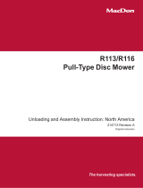
ELECTRICAL SCHEMATIC FOR TV 140 WITH AUXILLARY PUMP - REWORK:

Form 46749 Rev. A (E21175) Page 9 of 9
Model 801 Adapter For TV 140 with Auxiliary Pump
REWORK INSTRUCTIONS
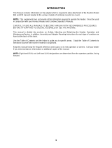
801 ADAPTER – HYDRAULIC SCHEMATIC:
/