Raypak Y-200 User manual
- Category
- Water heaters & boilers
- Type
- User manual
This manual is also suitable for

!"" "
!" #"!
Catalog No. 5000.62I Effective: 11-03-10 Replaces: 09-28-09 P/N 241125 Rev. 10
&!,80,9
2,*:8540*502,8!,7;,4*,8;:+558
,9,:54:852!?9:,3

2
is a registered trademark of Underwriters Laboratories Inc. ®
Rev. 10 reflects the following:
Changes to: Fig. 7 on page 11, Program Mode instructions on page 16, Illustrated Parts List on page 38
Additions: None
Deletions: None

3
""!
""!"&
!" #"!
" #"
Concept of Operation 4
Y-200 Controller Configurations 5
Y-200 Options 5
!""
Mechanical Installation 6
Electrical Installation 6
Controller Field Wiring 8
Communication Field Wiring 9
Air Temperature Sensor Installation 9
Water Temperature Sensor Installation 10
Power Test 11
Installation Verification Procedure 12
"
'"
Control Screens 13
Circuit Board Layout 15
Keypad 16
Control Screen Displays &
Programming 17
01 Initial Screen 17
02 Primary Parameters 17
03 Control Band 18
04 Offset 19
05 Holiday 20
06 Reset Ratio 20
07 System Status 22
08 Water Temperature 23
09 Outdoor Cut-Off Temperature 23
10 Outdoor Cut-Off Deadband 23
11 System Monitor 24
12 System Temperatures 24
13 Auxiliary Delay 25
14 Boiler/Stage On Delay 25
15 Boiler/Stage Off Delay 26
16 PID 26
17 System Temperatures 27
18 Lead Change Time 27
19 Password 28
20 Setup 28
21 System Test 29
22 Set Password 29
23 Water Temperature Limits 29
24 Master Unit 30
25 Slave Unit 31
26 LonWorks 31
27 Factory Defaults 31
28 User Defaults 32
29 Modem Password 32
30 Alarm Call Telephone 33
31 Alarm Call ID 33
32 Alarm Call Retry 33
33 Alarm Call Events 33
34 PID 34
Master Unit with Slaves 34
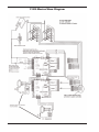
Y-200 Master/Slave Diagram 36
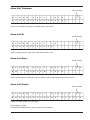
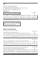
Sensor Resistance 37
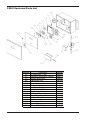
Illustrated Parts List 38
% "&

4
&@! !"
"
!"&!" #"!
Thank you for selecting the Raypak Y–200 Series
Electronic Boiler Control. It is our sincere hope that
you will enjoy its outstanding design, ease of use and
energy-saving features.
2,(9, ,.09:,8
Before proceeding any further, please take a moment
to complete the enclosed user registration form and
mail a copy to: Raypak, Inc., Department Y–200, 2151
Eastman Avenue, Oxnard, CA 93030.
" #"
The Y-200 Series Electronic Boiler Control (controller)
is a microprocessor-based boiler management system
designed to control either single or multiple stage-fired
boilers. Ideally suited for use in hydronic heating and
domestic hot water supply applications, this controller
has been engineered with the flexibility and raw power
to tame the most demanding control situations.
Utilizing state-of-the-art control algorithms, the Y-200
Series minimizes operating costs by maximizing ener-
gy efficiency.
54*,6:5-6,8(:054
The controller is an outdoor reset control that is perfect
for managing hydronic heating systems. Two tempera-
ture sensors are used to control system response.
One sensor is used to monitor the outdoor tempera-
ture, the other sensor is used to regulate the
temperature of the system water. By varying the tem-
perature of the heating medium in response to
changes in the outdoor temperature, the Y-200 Series
provides the ultimate in personal comfort and efficien-
cy of operation.
The controller is also well adapted to domestic hot
water supply duty. By disabling the outdoor reset func-
tion, the Y-200 behaves as an energy-wise boiler
sequencer. With the ability to control multiple firing
stages, and such features as a revolutionary selec-
table lead-lag protocol, the Y-200 redefines
"controllability" in domestic water applications.
The controller is equipped with an energy-saving
warm-weather shutdown capability. When the outdoor
temperature rises above an adjustable "Outdoor Cut-
off Temperature," the system automatically transitions
to a dormant state. This prevents the system from
wasting energy trying to heat a building that is already
at a comfortable temperature.
Once the outside temperature has fallen to the point
that the system requires heat input to maintain the
building temperature, the Y-200 is reactivated and will
hold the system temperature at the required point.
For replacement items, see page 38.
" These instructions are intended for use by
qualified personnel who are specifically trained and
experienced in the installation of this type of
equipment and related system components.
Installation and service personnel may be required
by some states to be licensed. If your state requires
certification, be sure your contractor bears the
appropriate license. Only qualified persons shall
attempt to repair this equipment. Repair must be
according to these instructions.
% Improper installation, adjustment,
alteration, service or maintenance may damage the
equipment, create a hazard resulting in
asphyxiation, explosion, fire, electric shock, personal
injury or property damage, and will void the warranty.
#" MORE THAN ONE (1) SUPPLY
SOURCE. THIS APPLIANCE HAS PROVISIONS
TO BE CONNECTED TO MORE THAN ONE (1)
SUPPLY SOURCE. TO REDUCE THE RISK OF
ELECTRIC SHOCK, DISCONNECT ALL SUCH
CONNECTIONS BEFORE SERVICING.
#" RISK OF ELECTRIC SHOCK. MORE
THAN ONE (1) DISCONNECT SWITCH MAY BE
REQUIRED TO DE-ENERGIZE THE EQUIPMENT
BEFORE SERVICING.

5
&54:8522,854-0.;8(:0549
&6:0549
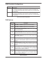
Model No. Description
Y-241 4-Stage Controller - Includes main controller assembly, air temperature sen-
sor assembly (P/N 068634), water temperature assembly (P/N 068635) and
one (1) stage contact board. Main controller includes one (1) mounted auxiliary
contacts board.
Y-281 8-Stage Controller - Includes main controller assembly, air temperature sen-
sor assembly (P/N 068634), water temperature assembly (P/N 068635) and
two (2) stage contact boards. Main controller includes one (1) mounted auxiliary
contacts board.
Table A: Y-200 Controller Configurations
Table B: Y-200 Options
Option No. Description
Y-300 Alarm Bell, 3” diameter. Shipped loose for field installation.
Y-301 Alarm Bell, 4” diameter. Shipped loose for field installation.
Y-302
Second 4-stage Expansion Board. Converts Y-241 to Y-281. Ships
loose for field installation.
Y-303
Auxiliary Relay Board. Adds control functions for external equip-
ment such as combustion air louvers. Ships loose for field installation.
Y-304
Slave Cable. Connects slave units to the master controller. Ships
loose for field installation.
Y-305
4-20 mA/2-10 VDC Control Board. Accepts 4-20 mA or 2-10 VDC
input from external system such as a BMS to force a specific setpoint.
Ships loose for field installation. Separate instruction manual; see
5000.64.
Y-306
Inlet/Outlet Sensors. Provides a PAIR of sensors for the inlet and
outlet temp. sensing ports. Displays temp. but does not affect control
algorithm.
Y-307
LonWorks Module. Provides full communication between a Y-200
series controller and a LonWorks-enabled system. Cannot have
BOTH this AND a modem. Shipped loose for field installation.
Separate instruction manual; see 5000.63.
Y-308
Modem Module. Provides full communication between a Y-200
series controller and an external system. Cannot have BOTH this
AND a LonWorks. Shipped loose for field installation. Separate
instruction manual; see 5000.65.

6
!""
If the controller was not mounted on the boiler by the
factory, care should be taken to select a suitable
mounting location. The controller should be mounted
on a solid and permanent base. The unit should be
readily accessible for maintenance and installation
purposes, and should be mounted so that the display
is at a height and location convenient for viewing.
,*/(40*(249:(22(:054
Install the controller within 30 feet of the boiler(s). It
must be mounted vertically with the conduit holes fac-
ing downward. The conduit holes are sized to
accommodate standard 1/2" conduit fittings. If addi-
tional or larger conduit fittings are required, locate the
conduit connections on the bottom of the module.
Slave units, if present, should be installed adjacent to
the master unit. (Y-304 slave cable is approximately
five feet long.)
Mount the controller using the mounting bracket and
appropriate hardware in four (4) places.
A minimum of eighteen (18) inches clearance from the
front, and six (6) inches clearance on all other sides is
required for service access. The hinged right side of
the box should be installed with sufficient clearance
(minimum 3” from bolt hole on the right side) to open
the cover.
An electrical distribution sub-panel containing appro-
priate disconnect switches and surge suppressors is
required at or near the equipment location(s).
2,*:80*(249:(22(:054
Requires: 120 VAC, Draws 0.5 amp; 60 Hz.
120 VAC Feeder Circuits: Install a surge protection
device sized appropriately for your installation at each
module.
Install a separate disconnect means for each load.
Use appropriately sized wire for equipment as defined
by NEC and/or local code. All primary wiring should be
no less than 125% of minimum rating.
It is strongly recommended that the controller and the
boiler(s) be supplied from the same power source.
Install conduit as appropriate.
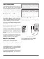
/,*1&5;85=,8!5;8*,
Using a Volt-ohm meter, check the following voltages
at the circuit breaker panel:
AC = 108 Volts AC Minimum, 132 Volts MAX
AB = 108 Volts AC Minimum, 132 Volts MAX
BC = Must be less than .6 Volts AC
" Shielded 18 (AWG) stranded gauge wire
must be used to connect the sensors to the
controller. The shielded cable should be protected by
conduit whenever possible.
" Minimum 18 AWG, 105°C, stranded wire
m
ust be used for all low voltage (less than 30 volts)
external connections to the unit. Solid conductors
should not be used because they can cause exces-
sive tension on contact points. Install conduit as
appropriate. All high voltage wires must be the same
size (105°C, stranded wire) as the ones on the unit
or larger.
CIRCUIT
B
REAKER
WHITE
GROUND
BLACK
GREEN
AB C
VOLT-OHM
METER
Fig. 1: Volt-ohm Meter

7
5=,8:5:/,54:8522,8
• Observe (follow proper) 652(80:?.
•
Observe proper wire colors while making electrical
connections.
• Provide an external surge suppressor capable of
maintaining system integrity.
• Provide overload protection and a disconnect
means for equipment serviceability as required by
local and state code.
• Conduit cannot be used as the ground. ("/,8,
3;9:
),(A% B.85;4+)
• $,8? 3658:(4: A grounding electrode con-
ductor shall be used to connect the equipment
grounding conductors, the equipment enclosures,
and where the system is grounded, the grounded
service conductor to the grounding electrode.
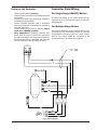
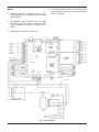
Fig. 2: Wiring Diagram
54:8522,80,2+%0804.
58!04.2,!:(.,502,89
A
ll stage connections on the control board are con-
nected at the {TH} (Thermostat) location on the boiler
wiring diagram.
58;2:062,!:(.,502,89
First stage connections on the control board are con-
nected at the {TH} (Thermostat) location on the boiler
wiring diagram. Second (or third, etc.) stage connec-
tions on the control board are connected at the
locations shown on the boiler wiring diagram.

8
5:,9
1
. Tighten terminal strip clamping screws to 2.5 in-
lbs. Breakage from over-torquing is not covered
under warranty.
2
. Use stranded copper conductors only. For supply
connections, use wires sized on the basis of 60°C
(140°F) ampacity and rated a minimum 90°C
(194°F).
3. Install disconnect for each control unit.
Fig. 3: Wiring Diagram
4
. For external building control or thermostat control,
remove wiring to J6 (CHF) connector and activate
with 12 to 28 VAC.

9
533;40*(:054 !%0804.
,7;08,+-586:054(2!2(<,
#40:9
&!2(<,()2,49:(22(:054-853
!?9:,354:8525+;2,
• Y-304 slave cable or equivalent shielded commu-
nications cable (Belden #9842, Belden #8132 or
Alpha 3492C) must be used. Maximum cable
length 100 ft. Correct polarity must be observed.
Make use of wire color coding to ensure polarity.
• The shielding [foil wrapper-bare wire (drain)]
MUST be grounded. Grounding is done at the
Master Y-200 Control only. DO NOT ground the
shield at the slave unit end of the cable.
• Note: Equivalent shielded cable must be suitable
for RS485 communication applications; must have
100-140 ohm impedance and less than 30 pico-
farad per foot capacitance.
• Must be installed in conduit that does not contain
any other wiring.
• Port J18 (see Fig. 4) is used for the interconnec-
tion between the master controller and slave units.
• Master/Slave interconnection should be wired
from Master to Slave #1, Slave #1 to Slave #2,
Slave #2 to Slave #3, and Slave #3 to Slave #4.
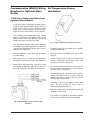
08",36,8(:;8,!,4958
49:(22(:054
• Locate the sensor on the coldest side of building,
usually the north side.
• Install the sensor in a shaded area, out of direct
sunlight.
• Locate no higher than 2/3 way up the side of the
building, or between the 2nd and 3rd floor if the
building is more than 3 stories tall.
• Do not locate under an overhang, near wall cor-
ners, near drafts from stacks, air moving devices,
windows, doors, or balconies.
• Shielded twisted pair (18 AWG) must be used for
sensor connections. Polarity must be observed.
Cable length shall not exceed 300 feet, and the
shielding must be grounded.
• Grounding is done at the Master Y-200 control
ONLY. Do Not ground the Slave units or
Temperature Sensor enclosure.
• Must be installed with properly-sized conduit that
contains no other wiring.
• The outdoor air temperature and water tempera-
ture sensor are identical and interchangeable.
Fig. 4: Master RS485 Communications Cable
Schematic
Fig. 5: Typical Outdoor Air Temperature Sensor

10
%(:,8",36,8(:;8,!,4958
49:(22(:054
?+8540*,(:04.6620*(:0549
• Hydronic installations may require outdoor reset
function. See page 11 and screen 02.
• Ensure shielded cable length does not exceed 300
feet. Use 18 AWG shielded wire for sensor con-
nections.
• Must be installed in properly-sized conduit with no
other wiring.
• Locate the water sensor as shown in Fig. 6
12”
M
AX
5’ MAX
5
’MAX
4ORMORESTAGES OR
4:1 TURN DOWN OR HIGHER
Fig. 6: Typical Water Sensor
" When the system involves a variable-speed
pump, it is recommended that the temperature
sensor be installed in the tee connecting boiler outlet
piping to the system. This is to ensure the control
can respond to the changing conditions of the
system by placing the sensor as close to the blend
location as possible and then provide an appropriate
and measured response to maintain desired system
delivery temperature.
" Piping diagrams in this manual are not
intended to replace an engineered piping system.

11
53,9:0*5:%(:,8!;662?
6620*(:0549
• Outdoor reset function should be disabled. See
screen 06 and 24.
5=,8",9:
/,*15=,8
Utilizing a Volt-ohm meter (VOM) monitor the following
on the controller for proper voltage levels. Check at the
Terminal Block (TB-1).
Fig. 7: Domestic Hot Water Supply
From To Indication
TB pin 1 TB pin 2
108 VAC to 132
VAC
TB pin 1
Single Point
Ground
108 VAC to 132
VAC
TB pin 2
Single Point
Ground
Less than 0.6 VAC
Table C: Voltage Measurements

12
49:(22(:054$,80-0*(:054
85*,+;8,
,.09:,8
❏
Before proceeding any further, please verify that
the user registration form has been completed and
mailed.
,*/(40*(249:(22(:054
❏
Verify that the mechanical installation has been
completed in accordance with the instructions.
;:+55808",36,8(:;8,!,4958
❏
Verify that all Outdoor Air Temperature Sensor
installation parameters have been met.
%(:,8",36,8(:;8,!,4958
❏
Verify that the Water Temperature Sensor installa-
tion parameters have been met.
6:054(27;063,4:
❏ Verify that optionally ordered equipment installa-
tion parameters have been met.
!?9:,35+;2,49:(22(:054
❏
Verify electrical power wiring connections.
❏ Verify electrical connection torque requirements.
❏ Verify Outdoor Air Temperature Sensor wiring.
❏ Verify Water Temperature Sensor wiring.
❏ Verify Power Test has been completed successful-
ly.
"
'"
T
his system is configured utilizing a LCD display (2
lines, 20 characters each) with keypad for data entry.
Open the front cover of the Control Box for access to
the LCD display and keypad. Open the control panel to
gain access to the interface connections.
REFER TO THE TABLES ON THE FOLLOWING
PAGES AND THE DISPLAY SCREENS FOR
DETAILED CONFIGURATION INSTRUCTIONS.
" Controller is shipped with factory defaults.
Your system may require different program settings.

13
54:852!*8,,49
To access programming mode: Press and hold the
"
MODE" button for 4 seconds. When in Program
mode, cursor is blinking on first settable parameter.
U
P/DOWN arrows change parameter. LEFT/RIGHT
arrows move to next selectable parameter.
Table D: Control Screens
" Once programming is finished, go to
Screen 28 to program the USER DEFAULT
SET_UP. Then open the front panel and press
the SW3 reset button on the motherboard to save
t
he new programming.
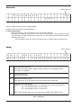
SCREEN DESCRIPTION FACTORY DEFAULT
Initial Screen 01 Displays the product identification and version of software. None
Calendar, Time,
Initial Setpoint
02
The present month, day, year and time in a 24-hour clock
format; setpoint temperature.
None
°F or °C 02
Temperature can be displayed in degrees Fahrenheit or
Celsius.
Default Value = °F
Setpoint 02
40 to 220°F (4.4 to 104.4°C); the system output temperature
desired when the outdoor temperature is 70°F (21.1°C); or in
domestic hot water applications, the desired water temperature.
Default = 140°F
(60°C)
Control Band 03
1 to 10°F; the temperature above and below the Target
Temperature at which the boiler turns off and on. NOTE: The
Control Band is disabled in PID operation. If the Control Band is
adjusted during PID operation, it disables the PID function.
Default = 3°F
No value when in PID
Offset 04
Degrees of offset added to or subtracted from the initial
setpoint at the date and time selected.
Default = OFF
Setting Holiday 05 Data from screen 04 is combined with these screen settings. Default = 00-00-RH
Reset Ratio 06
None (for Domestic Hot Water Application ONLY) or 0.01:1 to 8:1;
determines how much the internally-calculated Target
Temperature will change for a given outdoor temperature change.
Default value =
200°F@10°F
(93.3°[email protected]°C)
System Status 07 Shows the status of the system. None
Water
Temperature
Limits
08
Maximum "USER" water temperatures 235°F (112.7°C) and
Minimum water temperatures 40°F (4.4°C) Display Only.
Max default value =
180°F / 82.2°C
Min default value =
105°F / 40.5°C
Changes: Screen 23
Outdoor Cutoff
Temperature
09
32 to 200°F (0 to 93.3°C), a warm-weather shutdown feature.
When the outdoor temperature exceeds this setting, the boiler
will not fire unless placed in manual override mode.
Default value = 75°F
(23.8°C)
Outdoor Cutoff
Deadband
10
-01 to -10°F; the number of degrees below the Outdoor
Cutoff Temperature which causes the Outdoor Cutoff
Temperature to reset.
Default value = -3°F
System/Network
Monitor
11
Displays the Pump, Boiler, Stage and Auxiliary contact
status. If flashing, contacts are closed (ON).
This screen is
DISPLAY only.
Outdoor Water
TAR
12
Displays the current Outdoor Air, System Water and Target
Temperature in degrees °F or °C.
Default = °F
AUX Delay 13
000 to 600 seconds; determines when the pump shuts off
after entering Outdoor Cut-off mode.
Default = 180 seconds
Boiler/Stage On
Delay
14
0 to 600 seconds; sets the time interval between sequential
boiler start-ups. 0 to 600 seconds; sets time interval
between stages turning on.
Default = 10 seconds
Disabled in PID

14
(4;(2<,880+,
Internal switches have been provided on each of the stage modules that can be used to manually override the
microcontroller. See switch SW1 on each stage board, page 15.
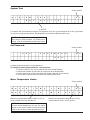
Table E: Control Screens (Continued)
S
CREEN
D
ESCRIPTION
F
ACTORY DEFAULT
Boiler/Stage Off
Delay
15
0 to 600 seconds; sets the time interval between sequential
boiler start-ups. 0 to 600 seconds; sets time interval
b
etween stages turning off.
Default = 10 seconds
Disabled in PID
Standard or PID 16
Selects either Standard or PID operation. If PID is selected
then PID & Interval is programmable using screen 34.
Default = PID
Boiler Inlet/Outlet
Delta(Optional)
17
Displays the boiler inlet and outlet temperature in °F or °C
and the difference (delta) between them. (Requires 4-sensor
installation, option Y-306.)
INLET / OUTLET =
Delta T
Auto Lead-Last 18
The lead change time in hours, the lead and last boiler
numbers and the mode (either Auto or Manual).
Manual:
Default = 100 hours
Password 19
Used to enter a password. This allows access to screens 20
through 34.
Default = AAA
To change: Screen 22
Unit Setup/
Network
20
Sets up the pump, boiler and stage configuration for the
System Monitor (Screen 11). Preset = 2 boilers / 4 stages.
Default =
PBSSSBSSSAAA
Note: See Table I
System Test 21
When ACTIVE, initiates auto system test and displays all
screens.
Default = Not Active
Set Password 22 Changes the current user password. Default = AAA
Water
Temperature
Limits
23
Sets Maximum and Minimum water temperature limits
allowed by the user in the Water Temperature Screen
Min. Default = 105°F
(40.5°C), Max. Default =
210°F (98.8°C)
Master/Slave
Unit
24
Displays the number of sensors utilized, relays (stages or
boilers) and Aux contacts.
Default = Master
Slaves
Connected
25 Selects the number of slave units connected, if any. Default = 00
LonWorks 26
If ON, the LonWorks network will be active.
Default = OFF
Factory Defaults 27 If YES selected, the factory defaults will be restored. Default = NO
User Defaults 28
If YES is selected, the User Defaults can be stored or
invoked.
Default = None
Terminal
Password
29
Used to enter a password for modem operation.
Default = AAA
Alarm Call Tele 30
Modem system telephone number to be called when a fault
occurs.
None
Alarm Call ID 31
Modem system ID person or place to be called when a fault
occurs.
None
Alarm Call Retry 32 Modem system error call retries. None
Alarm Call
Events
33 Modem system error indications. None
PID Settings 34 Configures PID operation.
Default =
Interval = 05
KP = 06
KI = 05
KD = 01

15
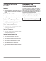
08*;0:5(8+(?5;:
Main Circuit Board
draoB yrailixuAdraoB yaleR egatS-4
1
SW3
Reset Switch
Manual Override Switch
Manual Override Switch
Fig. 8: Circuit Board Layout

16
,?6(+
583(25+,
Move to next screen
Not active except in special modes
Move to previous screen
Not active except in special modes
To access programming mode: Press and hold
"MODE" button for 4 seconds. If no button is
pressed while in PROGRAM mode for 30 seconds,
screen returns to normal mode
Increase selected parameter
Move to next programmable
parameter
Decrease selected parameter
Move to previous programmable
parameter
When in PROGRAM mode, cursor is blinking on first
settable parameter. If no button is pressed for 30
seconds, screen returns to NORMAL mode. Press
"MODE" button to store change and return to NOR-
MAL mode
Push the "MODE" button to turn off
the alarm horn
Once programming is finished, press the SW3 reset button on the motherboard to save the new
programming.
85.8(35+,

17
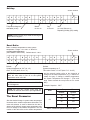
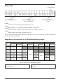
54:852!*8,,40962(?9
85.8(3304.
10CNIKAPYAR
Y- SERI ES VER XX . XXX
erawtfos fo rebmun noisreVnoitacifitnedi tcudorP
This is the initial screen displayed after system start-up, provided that there are no faults.
IN I T IAL SETPOINT° F02
MM - D D - Y Y H H M M X X X . X °
Calendar:
Month-Day-Year
Current time:
24 hour clock
Fahrenheit or Celsius Screen number
System water temperature desired at
outdoor temperature of 70°F (21.1°C)
Range: 40°F to 220°F(4.4°C to 104.4°C)
Default Value: 140°F (60°C)
Screen number
40:0(2!*8,,4
803(8?(8(3,:,89

18
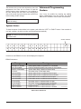
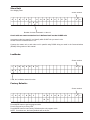
54:852(4+
30DNABLORTNOC
XX .X° F
*C Band is a range of temperature above and below
the target temperature.
Range: 1°F to 10°F (.5°C to 5.5°C)
Default value is 3°F
S
creen number
Fahrenheit or Celsius
" The above settings are recommended at
initial installation. For maximum performance and
system efficiency, these settings should be modified
as required to meet such parameters as system
capacity, location and usage.
" The Control Band is disabled when the unit
is operating in PID mode.
54:852(4+85658:054(242?
The Control Band sets the maximum temperature above and below the Target Temperature (which is determined
by the embedded microcontroller) between which the system temperature may deviate.
This provides a control dead-band that prevents the boiler from short-cycling in proportional mode.
" PID mode will be disabled if you adjust the
control band.

19
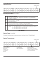
40FFOTESFFO
Press "MODE" to select "OFF" or "ALL" or "FULL WEEK"
"OFFSET" screen
Screen number
40LLATESFFO
—— — X : H H M M + X X . X ° F
There are six offset adjustments
allowed for each calendar day.
Screen number
"ALL" means every day has the same parameters.
Time in 24-hour
clock mode.
-99 to 99 degrees of offset.
(+) adds to or (-) subtracts from the
initial setpoint (screen 02) to become
active at selected time.
OF F S ET F U LL WEE K 0 4
XX X X: HHMM +X X . X ° F
There are eight days of selectable offsets: MON FRI
TUE SAT
WED SUN
THU HOL (Holiday)
Screen number
"FULL WEEK" screen
+, blank or –
+, blank or –
Fahrenheit or Celsius
Fahrenheit or Celsius
Default "OFF" screen
To set an offset, select the day or choose "ALL" for all days. Set the values in degrees. A positive (+) OFFSET
will increase the Water Target Temperature. A negative (-) OFFSET will decrease it. An offset value of 00.0 will
return it to its original value.
-99 to 99 degrees of offset are available.
--9,:

20
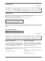
520+(?
SE T T ING HOL I DA Y 0 5
H
OL#XX XX—XX—XX
Thirty two holidays are
selectable (01-32)
Month:
01 thru 12
Day:
01 thru 31
Year:
01 to 99; Below 01 is
Repeating Holiday (RH) setting
RS T RA T I O X . XX : 1 0 6
XX X . X@7 0 X XX . X@XX
Default:
System temperature at 70°F (21.1°C)
140°F @ 70°F (60°C @ 21.1°C)
Ratio of outdoor temperature to water system
temperature. Range: . 01:1 to 8:1 or "None" for
constant water temperature
(then TARGET=SETPOINT). Default value is 1.00:1.
Screen number
Screen number
Default:
System temperature at °F
This value is 200°F @ 10°F (93.3°C @ -12.2°C)
,9,: (:05
"/, ,9,:(8(3,:,8
Sets the desired change in system water temperature
increases as the outdoor temperature decreases. The
reset ratio selector is used to determine the rate of
change of the boiler(s) output water temperature rela-
tive to a change in the outdoor temperature. The first
number of the ratio refers to the outdoor temperature
and the second number refers to the degree(s) of
change for the water temperature, e.g., a ratio of 2:1
means for every 2° change in outdoor temperature,
the System Temperature will change 1°. (The reset
temp cannot exceed the temp limits set on screen
#08.)
Example: Setpoint = 135°F
"Previous screen (04) is used for entering the
offset value in degrees.
" The reset ratio can be modified by changing
either the ratio value in line #1 or the system
temperature value in line #2.
" When the reset ratio selected is "NONE",
line 2 disappears.
" Use reset ratio "NONE" when using this
controller for domestic hot water or pool applications.
Ratio
Temperature °F
Outdoor System
2:1
70 135
60 140
40 150
20 160
Table F: Outdoor to System Temperature Ratio
Page is loading ...
Page is loading ...
Page is loading ...
Page is loading ...
Page is loading ...
Page is loading ...
Page is loading ...
Page is loading ...
Page is loading ...
Page is loading ...
Page is loading ...
Page is loading ...
Page is loading ...
Page is loading ...
Page is loading ...
Page is loading ...
Page is loading ...
Page is loading ...
Page is loading ...
Page is loading ...
-
 1
1
-
 2
2
-
 3
3
-
 4
4
-
 5
5
-
 6
6
-
 7
7
-
 8
8
-
 9
9
-
 10
10
-
 11
11
-
 12
12
-
 13
13
-
 14
14
-
 15
15
-
 16
16
-
 17
17
-
 18
18
-
 19
19
-
 20
20
-
 21
21
-
 22
22
-
 23
23
-
 24
24
-
 25
25
-
 26
26
-
 27
27
-
 28
28
-
 29
29
-
 30
30
-
 31
31
-
 32
32
-
 33
33
-
 34
34
-
 35
35
-
 36
36
-
 37
37
-
 38
38
-
 39
39
-
 40
40


Raypak Y-200 User manual
- Category
- Water heaters & boilers
- Type
- User manual
- This manual is also suitable for
Ask a question and I''ll find the answer in the document
Finding information in a document is now easier with AI
Related papers
Other documents
-
A.O. Smith 1700 User manual
-
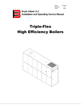 Bryan Boilers Triple-Flex 250 User manual
-
RBI FUTERA FUSION Series User manual
-
Emerson E2 User manual
-
Honeywell S7999B User manual
-
Burnham Sage Boiler Control User manual
-
Weil-McLain SlimFit 1000–2000 Series 1 User manual
-
Aerco 5R5-384 User manual
-
Bradford White BOCH2000 User manual
-
Aerco BOILER MANAGEMENT SYSTEM II 5R5-384 Installation, Operation & Maintenance Instructions Manual
