Broan E3 User manual

Category
Split-system air conditioners
Type
User manual

This manual is also suitable for

IMPORTANT: Read this owner information
to become familiar with the capabilities and
use of your heating appliance. Keep this
literature where you will have easy access
to it in the future. If a problem occurs, check
the instructions and follow recommenda-
tions given. If these suggestions don’t
eliminate your problem, call the appropriate
NORDYNE distributor. A distributor service
list is included with this appliance.
WARNING:
Do not store or use gasoline or other
ammable vapors and liquids in the
vicinity of this or any other appliance.
Improper installation, adjustment,
alteration, service or maintenance
can cause injury, property damage,
or death. Refer to this manual. For
assistance or additional information
consult a qualifi ed dealer or service
agency. To avoid personal injury or
property damage, ask a service
technician to inspect the furnace and to
replace any part of the control system
which has been under water.
SECTION 1. OWNER INFORMATION
OPERATING INSTRUCTIONS
Before Operating System
Before operating your heating/cooling system
(see Figure 1), make sure that:
Control panel covers are closed.
Blower and/or relay control plugs are
plugged in.
Fan switch is set to “AUTO” (E3EH units
only).
CAUTION:
No user serviceable parts inside
control panel. DO NOT OPEN.
Circuit breakers are in “ON” position.
All power supply switches for furnace and
outside unit (if installed) are turned on.
Furnace door is closed and properly
latched.
Refer to the owner’s manual supplied with the
optional heat pump or air conditioner for further
information.
CAUTION:
For optional A/C or H/P systems,
always wait at least fi ve minutes after
the system shuts off before restarting
the system. Observe this procedure
when operating the system per the
following instructions.
Owners Manual/Installation Instructions
E3 Series (Air Conditioner/Heat Pump Air Handler)
Downfl ow, Up ow Electric Furnaces
2
3
Indoor Coil
(optional)
Coil Air Filters
(used with indoor coil)
Furnace Air Filter
(NOT used with
coil air filters)
Control Panel
Cover (left)
Data Label
Circuit Breakers
Control Panel Cover (right)
Blower
Figure 1. Furnace Parts Identifi cation
Model Identifi cation
10 20 30
50 60 70 80 90
SYSTEM
HEAT OFF COOL
VENTILATE
ON AUTO
Temperature Selector
Temperature
Scales
System Switch
(optional sub-base)
Fan Switch
(optional sub-base)
E 3 EB - 010 H
Product Type
E - Electric Furnace
Generation
3 - Third Series
Product Identifier
EB - A/C Blower Equipped Relay
EX - Multi-Speed, X13 Motor
Used with Platinum Series
Electrical Code
H - 240-1-60
Primary Capacity
010 - 10 kw 012 - 12 kw
015 - 15 kw 017 - 17 kw
020 - 20 kw 023 - 23 kw
4
To Operate System in Cooling Mode
NOTE: The “FAN ON/FAN AUTO” (fan switch)
and “HEAT/OFF/COOL (system switch) are
located either on your thermostat (if it’s supplied
with a sub-base) or on the relay box added to
your furnace.
1. Make sure blower selector switch is on
“Auto.
2. Set fan switch to “AUTO.
3. Set system switch to “COOL.
4. Set thermostat temperature selector to
desired comfort level.
To Operate System in Heating Mode
1. Make sure blower selector switch is on
“Auto.
2. Set fan switch to “AUTO.
3. Set system switch to “HEAT.
4. Set thermostat temperature selector switch
to desired comfort level.
NOTE: Allow at least one hour for the room tem-
perature to stabilize before you make a second
adjustment to the thermostat setting. Once the
desired comfort level is established, make only
small adjustments to the thermostat setting to
meet changing temperature conditions.
To Operate Blower Continuously
1. Set blower selector switch to “ON” for summer
air circulation only (see Figure 1),
OR
2. If thermostat is equipped with optional
heating/cooling sub-base or relay box (see
Figure 1), set fan switch to “ON.
To Balance Air Distribution
1. On a typical day, set thermostat selector to
desired comfort level and operate system for
several hours with all air registers open.
2. With system on, check temperature in all
rooms.
3. Partially close registers in rooms that are
too warm (in heating mode) or too cool
(in cooling mode) and in rooms that are
infrequently occupied.
4. Re-check room temperature and adjust
registers as needed.
To Shut Off System
1. Make sure blower selector switch is on
“Auto”.
2. Set thermostat temperature selector to
lowest temperature setting, OR...
3. For thermostats with optional sub-base (see
Figure 1), or for systems with relay box, set
system switch to “OFF.
WARNING:
To prevent hazard of electrical shock
and injury from moving parts, be
certain the thermostat is off and the
furnace circuit breaker(s) are in the
“OFF” position before servicing. Close
and properly latch the outer door after
doing the following recommended
maintenance.
MAINTENANCE INSTRUCTIONS
Regularly
NOTE: If a cooling coil is installed, furnace
lter is not used.
1. Replace furnace air fi lter (see Figure 1),
OR...
2. Remove coil fi lters, wash, and allow to dry.
Re-install coil fi lters to original positions.
3. Vacuum or wipe clean interior of furnace
cabinet.
4. Clean all lint and dust from around fur-
nace.
Every Six Months
1. Vacuum or wipe away any dust or lint on
blower motor.
Before Each Heating Season
NOTE: If a cooling coil is installed, furnace
lter is not used.
1. Replace furnace air fi lter (see Figure 1),
OR
2. Remove coil fi lters, wash, and allow to dry.
Re-install coil fi lters to original positions.
3. Have a qualifi ed serviceman inspect all
furnace components and fi eld wiring and
clean and service heating system as
needed. If this furnace was installed with
aluminum power supply wiring, have ser-
viceman periodically check all connections
to prevent possible equipment failure and/or
re hazard. Do not attempt any service
function yourself which requires opening
furnace control panel covers.
5
BEFORE YOU CALL A SERVICEMAN
1. Make sure thermostat temperature selector
is set above room temperature for heating
or below room temperature for cooling. If
thermostat is equipped with heating/cool-
ing sub-base, make sure system switch
(see Figure 1) is set to “HEAT” for furnace
operation or set to “COOL for optional air-
conditioning operation.
2. Check main household service panel to
see if appropriate circuit disconnect(s) for
appliance power supply is on.
3. Refer to instructions under Before Operating
System for pre-operation checks.
4. Refer to instructions under Before Each
Heating Season for maintenance proce-
dures and recommended service checks.
5. Refer to owner’s manual provided with
optional air conditioner or heat pump (if
installed) for service and maintenance.
NOTE: All servicing of this heating appliance
other than the normal maintenance described in
this section must be done by authorized trained
service personnel. Do not open the control
panels (see Figure 1) at any time.
Please specify the complete model and serial
numbers shown on the furnace data label (see
Figure 1) for all warranty service and when or-
dering replacement parts or optional equipment.
Refer to the replacement parts list provided with
the furnace for part numbers.
OPTIONAL AIR CONDITIONER
AND HEAT PUMP
Your E3 Series electric furnace is approved for
use with an optional central air conditioner or a
heat pump. To adapt this heating appliance to
a “total comfort system, contact your nearest
NORDYNE distributor.
Optional air conditioners and heat pumps are
listed by Underwriters’ Laboratories (UL) or
Environmental Testing Laboratories (ETL) and
certifi ed by ARI and the Canadian Standards
Association (CSA), or Warnock Hersey or ETLC.
These cooling systems include energy-sav-
ing components to provide maximum cooling
performance at electrical energy usage levels
established by federal standards. Refer to the
operation instruction label on your furnace for
the optional air conditioning equipment approved
for your heating appliance.
SECTION 2.
INSTALLER INFORMATION
GENERAL
These instructions and specifi cations are pri-
marily intended to assist qualifi ed individuals
experienced in the proper installation of home
heating and air conditioning appliances. Some
local codes require licensed personnel for the
installation and service of this type of equip-
ment. Approved installation, operation, and
maintenance of this central heating system
appliance must be in accordance with the listed
specifi cations contained in these instructions
and other documents supplied with the furnace
and/or optional air conditioning equipment. Refer
to local authorities having jurisdiction for further
information.
Before beginning installation, read these instruc-
tions thoroughly. Follow all warnings and cautions
in the instructions and on the unit.
Improper installation, service adjustment, or
maintenance can cause explosion, fi re, electri-
cal shock or other conditions which may result
in personal injury or property damage. Unless
otherwise noted in these instructions, use only
factory-authorized kits and accessories when
modifying this product.
Overview of E3 Furnace
E3E(-) Series electric furnaces are available in
two models. E3EH models are equipped with the
standard two-speed blower. E3EH models can
be easily converted for use with NORDYNE split-
system air conditioners and heat pumps. E3EB
models are air-conditioning ready; that is, they
are equipped with a multi-speed (four-speed)
blower, blower relay, and cabinet insulation kit.
See Table 3 for cooling and heat pump availability
with factory installed blower.
For typical unducted return air downfl ow applica-
tions, an air-conditioner or heat-pump coil can be
installed by mounting the coil directly on top of
the furnace without adding sheet metal cavities
or cutting and trimming wood panels.
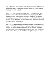
A return air grille for closet or alcove installations
is available. For downfl ow alcove installations,
the grille (with frame provided) may be attached
to the top of the furnace and all paneling and
trim fl ushed to it. This installation provides an
access door for future installation of NORDYNE
air conditioning or heat pump coils on top of
the furnace.
6
Power entrance for all models may be through the
right side or through the bottom of the unit (when
viewing the unit in a downfl ow position).
UNIT CHECKOUT
Before installing this furnace:
1. Inspect unit for possible shipping damage.
If shipping damage is found, fi le claim with
transportation company.
2. Record furnace model number and serial
number (see furnace data label) for future
reference.
3. Carefully read all instructions supplied with
optional equipment to be installed with
furnace.
CODES, SPECIFICATIONS, AND
REQUIREMENTS
Furnace Codes
Installation and wiring of this furnace, as well as
the design and construction of the home duct
system, must be in accordance with one or more
of the following codes:
HUD MANUFACTURED HOME CONSTRUC-
TION AND SAFETY STANDARD (Title 24,
Part 3280)
American National Standards (ANSI) A119.11,
C1-NFPA 7 (National Electrical Code)
CANADIAN STANDARDS (C.S.A.) Z240.6.1,
and Z240.9.1.
All local codes having jurisdiction shall also
apply.
Air Duct Codes and Specifi cations
Air ducts must be installed in accordance with
National Fire Protection Association standards
NFPA 90A and NFPA 90B, these instructions,
and all applicable local codes.
Materials: Air ducts must be aluminum,
tin plate, galvanized sheet steel, or other
approved materials for outlet or return air
ducts.
Construction: Snap-Lock or Pittsburgh-Lock
seams are preferred. All other types of seams
must be made tight to prevent leakage.
Sizing: Supply duct system must be designed
for proper air distribution. Static pressure
measured externally to furnace shall not ex-
ceed static pressure rating listed on furnace
nameplate.
Location of Openings: Duct system must be
designed so that no supply registers are lo-
cated in duct system directly below furnace.
Table 1. Miscellaneous Listings & Installation Requirements
Listing agency(s)
May vary by model, check the unit data label for
applicable agency listing mark.
Approved Installation Con gurations
Approved for: single/multistory residential or mobile/
modular/manufactured structures. Up ow, down ow,
(freestanding/closet/alcove)
Accessibility for Servicing Minimum of 18"(46cm) required in front of unit.
Minimum Clearance to
Combustibles
0" from all surfaces of furnace cabinet, ducts, optional
coil housing and plenum connector. No separate
subbase required for installations on combustible
ooring.
Minimum return air opening
required (total free area)
200 in (1290 cm ) heating only*
235 in (1516 cm ) A/C or H/P up to 4 ton installed
250 in (1613 cm ) A/C or H/P up to 4 ton w/1" clearanced
installed
390 in (2516 cm ) A/C or H/P up to 5 ton installed
*or return air grille and frame assembly p/n 902989 or
wall mount grille p/n 902999
Return air grille (closet or alcove
installation)
Use return air grille and frame assembly P/N 902989 or
equivalent for alcove installation.
Use wall mount return air grilled P/N 902999 or
equivalent for closet installation.
155 in (1000 cm ) must be added for 5 ton A/C or H/P
system.
7
Return Air Codes and Requirements
Unducted return air systems may be used for
closet or alcove installations.
NOTE: Applicable installation codes may limit the
furnace to installation in a single-story residence
only. Furnace installations other than closet or
alcove installations require ducted return air
systems.
Air return to the furnace must have a minimum
free area opening (see Table 1).
Acceptable fl oor or ceiling return air systems
for closet installations with return air entering
through an opening in the closet fl oor or ceiling
must meet all of the following requirements:
Return air opening into closet, regardless of
its location, must not be smaller than size
specifi ed on unit data label.
If located in fl oor of closet, return air opening
must be provided with means of preventing
its inadvertent closure by a fl at object placed
over opening.
Materials located in return air duct system
must have a fl ame-spread classifi cation of
200 or less.
Noncombustible pans having 1” upturned
anges must be located beneath openings
in a fl oor-return duct system.
Wiring materials located in return duct system
must conform to NEC Article 300-22(c).
Gas piping must not run in or through return
air duct system.
If return air opening is located below top
of furnace, a minimum clearance must be
provided between opening and furnace (see
“Accessibility for servicing” in Table 1).
Closed-Off Space Requirements
Living space not served by, and closed off from,
the return air ducts to the furnace by doors, sliding
partitions, and other means must be provided
with permanent, uncloseable openings in the
doors or partitions to allow air to return to the
furnace from all parts of the home. Return air
grilles, with a minimum open area of one square
inch for every fi ve square feet of living space
closed off from the furnace, must be provided
in the door or room partition.
OPTIONAL EQUIPMENT
Contact your nearest NORDYNE distributor for a
complete list of electric furnace accessories.
Return Air Grille
A return air grille and frame assembly (see Figure
2) is available for use in unducted return air instal-
lations. In downfl ow alcove installations, the grille
and frame assembly may be mounted directly
to the top of the furnace. In closet installations,
a wall mount grille is available for attachment
to a door or wall.
Optional Automatic Furnace
Damper #901083 -
Furnace may (not required) be equipped with
the optional automatic damper when a packaged
air conditioner is installed and connected to the
warm air duct system. This damper prevents
cooled air from discharging through the furnace
cabinet, causing excessive cooling of the immedi-
ate area. Refer to instructions supplied with the
damper for details.
Multi-Speed Blower Conversion
Package (4 or 5 ton):
Upgrade blower packages are available for
adding air conditioning or heat pump systems.
See furnace “Options and Compatibility” label
for systems available.
TYPICAL INSTALLATION OF
DOWNFLOW SYSTEMS OR
PLATINUM SYSTEM
The following steps describe installation instruc-
tions for an under-the-fl oor supply duct system
with a return air system that can be either
unducted or ducted. Duct connectors (Table 4)
are recommended for this application.
NOTE: Before installing this furnace, consider all
clearances for the installation and future servicing
of the furnace. Refer to Table 1.
Return Air and Filtering Systems
Furnaces may be installed with unducted or
ducted return air. For unducted return air
systems, either the optional grille and frame
assembly or the optional wall mount grille is rec-
ommended. For ducted return air systems with
air conditioners or heat pumps, either providing
an access panel in the duct or using the optional
coil cabinet is recommended. The duct system
must be properly sized so as to account for any
additional external static pressure produced from
the chosen fi ltering method.
8
Table 2. Optional Air Conditioning and
Heat Pump Equipment
Figure 3. Optional Rear Mounting Plate
(P/N 389080)
3"
(76 mm)
20-1/8"
(511 mm)
11/16"
(17 mm)
Notes:
1) For A/C and H/P use.
2) Includes coil fi lters.
3) For upfl ow or downfl ow installations.
4) For upfl ow A/C or H/P installations (includes one fi lter; use
lter from furnace to complete fi ltering system in this acces-
sory).
5) Standard in EB models.
Figure 2. Optional Accessories
20" (508 mm)
Cabinet
Insulation
Upflow Coil Cabinet
23 3/4" (603 mm)
29"
(737 mm)
NOTE: See Table 2 for descriptions
and notes
1
2
3
4
7
8
27"
(686 mm)
29"
(737 mm)
20"
(508 mm)
23 3/4"
(603 mm)
24 3/4” (628 mm)
Upflow Stand
20”
(508 mm)
20” (508 mm)
Item Number
(See Figure)
Description
1
4-Speed Blower
4 Ton - See notes: 1 & 5
5 Ton - See Note: 1
2
A.C./H.P. Relay Control
See Note: 1
3
Cabinet insulation Kit
See Notes: 1 & 5
4
A-Coil Conversion Kit
See Note: 2
5
Coil Cabinet
See Note: 3
6
Up ow Stand
See Note: 4
7 A/C and H/P Indoor Coils
8
Return Air Grille and
Frame
9
Table 3. Unit Specifi cations
1. Heating output rated at listed voltage. For outputs at voltages other than 240V, multiply Btuh rating by the following
factors: x 0.92 (230V), x 0.84 (220V), x 0.75 (208V)
2. Height is 56” with return air grille installed, 58” with coil cabinet and 72” with coil cabinet and upfl ow stand.
3. The factory installed blower for the EH models can be replaced with a multi-speed blower allowing the units to
accept up to 5 tons of air conditioning or 4 tons heat pump.
4. The factory installed blower for the EB models can be replaced with a multi-speed blower allowing the units to
accept up to 5 tons of air conditioning.
Electric Furnace Models
E3EH
010H 012H 015H 017H 020H 023H
Rated Heating Output, Btuh
(see note 1)
35,000 41,000 53,000 57,000 70,000 75,000
Watts (Total kw, Heating
Elements and Blower)
10.4 12.0 15.4 16.6 20.4 22.0
Supply Voltage 240 Volts/60Hz/1-Phase
Heating Elements,
No.(Total kw)
2 (10.0) 2 (11.6) 3 (15.0) 3 (16.2) 4 (20.0) 4 (21.6)
Blower Wheel Size 10.5" Dia., 8" Wide
Motor Speed,
H.P. Rating, Amps
2 Speed, 1/5 HP, 2.0
Test ESP, in. w.c. Max 0.3
Optional Cooling Available with
factory installed blower
2.0 - 3.0 Ton (see note 3)
Optional Heat Pump Available
with factory installed blower
2.0 - 3.0 Ton (see note 3) n/a (see note 3)
Air Filter (Standard) 16" x 20" x 1" (nominal)
Furnace Dimensions Width-20" (508mm), Height-29" (737mm) (see note 2), Depth-24 1/2" (623mm)
Electric Furnace Models
E3EB
010H 012H 015H 017H 020H 023H 023H 5-Ton
Rated Heating Output, Btuh
(see note 1)
35,000 41,000 53,000 57,000 70,000 75,000 75,000
Watts (Total kw, Heating
Elements and Blower)
10.4 12.0 15.4 16.6 20.4 22.0 22.0
Supply Voltage 240 Volts/60Hz/1-Phase
Heating Elements,
No.(Total kw)
2 (10.0) 2 (11.6) 3 (15.0) 3 (16.2) 4 (20.0) 4 (21.6) 4 (21.6)
Blower Wheel Size
11" Dia.,
8" W
Motor Speed,
H.P. Rating, Amps
4 Speed, 1/3 HP, 2.9
4 Spd,
3/4HP 3.8
Amps
Test ESP, in. w.c. Max 0.3
Optional Cooling Available with
factory installed blower
2.0 - 4.0 Ton (see note 4) 2.0 - 5.0 Ton
Optional Heat Pump Available
with factory installed blower
2.0 - 4.0 Ton
Air Filter (Standard) 16" x 20" x 1" (nominal)
Furnace Dimensions Width-20" (508mm), Height-29" (737mm) (see note 2), Depth-24 1/2" (623mm)
Electric Furnace Models
E3EX
010H 012H 015H 017H 020H
Rated Heating Output, Btuh
(see note 1)
35,000 41,000 53,000 57,000 70,000
Watts (Total kw, Heating
Elements and Blower)
11.4 13.0 16.4 17.6 21.4
Supply Voltage 240 Volts/60Hz/1-Phase
Heating Elements,
No.(Total kw)
2 (10.0) 2 (11.6) 3 (15.0) 3 (16.2) 4 (20.0)
Blower Wheel Size 10.5" Dia., 8" Wide
Motor Speed,
H.P. Rating, Amps
Multi-Speed, 3/4 HP, 6.0
Test ESP, in. w.c. Max 0.3
Optional Cooling Available with
factory installed blower
2.0 - 4.0 Ton
Optional Heat Pump Available
with factory installed blower
2.0 - 4.0 Ton
Air Filter (Standard) 16" x 20" x 1" (nominal)
Furnace Dimensions
Width-20" (508mm), Height-29" (737mm) (see note 2)
Depth-24 1/2" (623mm)
10
NOTE: Refer to the instructions supplied with
any additional accessories for further installa-
tion details.
Filtering Methods - Non-Ducted Return Air
1. Without A/C or H/P uncased coil:
- use the fi lter supplied with the furnace;
ensure that the fi lter is installed mat side
down between the fi lter retainer and furnace
top (see Figure 4).
2. With A/C or H/P uncased coil:
- use the optional coil fi lters; the fi lter sup-
plied with the furnace is not used; REMOVE
AND DISCARD THIS FILTER.
3. With optional coil housing:
- see coil cabinet instructions for specifi c
ltering methods.
Filtering Methods - Ducted Return Air
1. Without optional coil housing:
- install a fi lter with a minimum unrestricted
medium area of 324 square inches in the
duct above the coil that is accessible for
monthly cleaning or replacement by hom-
eowner.
2. With optional coil housing:
-install a fi lter with a minimum unrestricted
medium area of 324 square inches in the
duct above the coil that is accessible for
monthly cleaning or replacement by hom-
eowner.
Optional Duct Connectors for
Downfl ow Systems
Duct connectors are recommended for heated
air distribution in under-the-fl oor duct systems.
With this system, furnaces may be installed on
combustible fl ooring without a separate sub-
base. Also, the furnace rear mounting plate
(see Figure 3) supplied with the duct connec-
tors is recommended for use with this type of
installation.
Selecting Duct Connector
Non Platinum Duct Connector
1. Determine depth of fl oor cavity from surface
of fl oor to top of supply air duct (see Figure
5).
2. Select appropriate model from Table 4
which matches X-dimension of fl oor cavity.
To maximize air delivery, remove reducer
(C in Figure 5) to obtain largest open area
that will fi t duct/fl oor construction.
NOTE: Duct connectors may be
installed in any one of four positions.
Platinum Duct Connector
1. The 14” round duct connector (903896) is
designed to connect directly to a 14” ex-
duct.
A
B
19”
(483 mm)
19"
(483 mm)
TOP VIEW
X
Reducer
*Felt Seal
Corner
Spacers
C
*OPENING TO DUCT
A= 13-1/4" (337 mm)
B= 10-3/4" (274 mm)
WITH PLATE (C) REMOVED
OPENING BECOMES
13-1/4” x 13-1/4”
*Indicates only applicable for Finger Tab Duct Connector
x
SUPPLY AIR DUCT
FLOOR CAVITY
Figure 5. Duct Connector Selection (Non-Platinum)
Frame
Top of
Furnace
Fasteners (4)
Grille
Furnace Filter
(not used with
A/C or H/P)
Figure 4. Grille Support Frame and Grille
Assembly
11
Preparing Floor Opening(s)
1. Mark fl oor opening(s) as shown in Figure
6. Provide minimum clearances at rear
and right side walls of closet or alcove for
installation of furnace and wiring.
2. Cut oor opening on outside edge of marked
line so that opening is slightly larger than
area marked.
3. Additional provisions may be necessary
for optional air conditioning or heat pump
if refrigerant lines are installed elsewhere
than at the front of the furnace.
4. The refrigerant and entrance supply opening
dimensions may be adjusted ± 1/2”.
Installing Duct Connector
NOTE: The duct connector is designed for use
on ducts down to 12” wide. On typical ducts,
the fi nger tab duct connector may be installed
using Method B. On narrow ducts, there may be
insuffi cient clearance to bend the tabs on two
sides of the fi nger tab duct connector. In such
cases, use Method C or D. For screw down duct
connector use method E. For Platinum models
always use method A.
Method A - Platinum Series
NOTE: Flex duct used must have a minimum
temperature rating of 200
° F and meet all
other applicable codes and standards.
1. Place duct connector through opening in
oor. See Figure 9.
2. Connect 14” supply duct.
2-3/8" MIN
(60 mm)
"
6-1/4
23-3/4"
(603 mm)
20
"
3/4"
"10
14-1/2"
(368 mm)
3" (76 mm)
"4-1/4 "5
"3-3/8
REAR WALL OF ENCLOSURE
Furnace Outer
Door
Optional Supply Wire
Entrance
Optional
Refrigerant
Line
(Not required
for Platinum)
Center Line
17"
(432 mm)
14-1/2"
(368 mm)
16-5/8"
(422 mm)
(254 mm)
(86 mm)
(127 mm)
(108 mm)
(159 mm)
(19 mm)
(508 mm)
3-3/4"
(95 mm)
Furnace
Outline
A/C Or HP
Figure 6. Downfl ow Floor Cutout Locations (nominal dimensions)
Table 4. Floor Cavity Sizes
If "X"
oor cavity is:
Use Duct Connector
Model Part Number
English
Metric
(mm)
Finger
Tab
Screw
Down
7/8" 22 901987 904008
2" 51 901988 904009
4 1/4" 108 901989 904010
6 1/4" 159 901990 904011
8 1/4" 210 901991 904012
10 1/4" 260 901992 904013
12 1/4" 311 901993 904014
12
Rear Wall
Cut-out Area
Optional Supply
Entrance
Mounting
Plate
Floor
Opening
Refrigerant
Line
Opening
Supply Air Duct
Cut Duct Opening
1/16th. Larger Than
Plenum Connector
Figure 7. Rear Mounting Plate
Rear Wall
Secure Duct Connector &
Mtg Plate With 2 Flat Head Screws
or Nails At Dimpled Locations
Refrigerant
Line
Opening
Supply Air Duct
Mounting
Plate
Plenum
Bend Connector Tabs
Under Duct Opening
Figure 8. Duct Connector (Non Platinum)
4. Secure duct connector to fl oor with two
at-head fasteners at dimpled locations
(see Figure 8).
5. Secure connector to duct by bending bottom
tabs under and up against duct surfaces
(see Figure 10).
Method C
1. Attach tabs to sides of duct (one on each
side) using sheet metal fasteners or other
method, ensuring that the duct connector is
secure and sealed to the duct (see Figure
11).
2. Seal the duct fl ap edges with an approved
tape or compound for a leak-free joint.
Method B
1. Place duct connector through fl oor opening
with bottom tabs resting on top of supply
air duct. Mark cutout area around inside of
tabs.
2. Remove duct connector and cut out duct
opening slightly larger than area marked.
3. If using optional rear mounting plate (sup-
plied with duct connector), install it to back
edge of fl oor opening (see Figure 7). Re-
install duct connector in fl oor opening. A
shim may be used, if necessary, to ensure
the furnace is level.
13
Figure 9. Platinum Duct Connector
Method D
1. Score and cut top of metal duct as indicated
in Figure 12, Step 1 or Step 2. If using Step
1, also cut out metal from the shaded area
“A”.
2. Fold the duct fl ap “B” up (see Figure 12,
Step 3).
3. At the front-to-back of duct run (see Figure
12, area “A”), bend the duct connector tabs
and secure them directly to the duct.
4. At area “B”, bend the duct connector tabs up
and back over, around the duct connector
(see Figure 12, step 3).
Figure 10. Duct Connector Installation B
5. Fold/form the duct fl ap against the side of
the duct connector and attach as shown
(see Figure 12, Step 4). Use at least three
staples on each duct fl ap OR... if a 2X
block/joist is not provided, use at least two
sheet metal fasteners on each duct fl ap.
6. Seal the duct fl ap edges with an approved
tape or compound for a leak-free joint.
Method E
1. Apply a bead of caulking, mastic, or other
approved sealant around bottom side of
1/2” ange and restrictor plate, when ap-
plicable.
TABS
DUCT
1. INSERT DUCT CONNECTOR
INTO DUCT CUT-OUT
TABS
DUCT
2. BEND BOTTOM TABS OVER
AND ONTO THE UNDER-
NEATH DUCT SURFACE
14
Alcove Installation
1. Cut alcove rough openings to minimum
dimensions shown in Figure 13.
2. Attach frame assembly with four fasteners
(provided or equivalent) into pre-punched
holes on top of furnace (see Figure 5).
3. At manufacturers discretion, if additional
securing is required attach each side of
frame assembly to alcove opening using
holes provided.
4. Attach return air grille to frame assembly by
hooking grille over fl ange on top of frame
and into channel on bottom.
Closet Installation
NOTE: For closet installations, the return air
grille mounting frame is not used since the
furnace is located inside the closet (see Figure
14 and 15).
1. Cut return air opening in desired position
in door or wall, preferably above top of fur-
nace. Refer to Table 1 for return air opening
requirements.
2. Insert four fasteners, securing grille to door
or wall.
Furnace Installation
1. Install 240V supply circuit(s) and 24V wir-
ing to closet or alcove (see Figure 16 for
appropriate locations).
2. Locate the duct connector over duct and
carefully lower screw down duct connector
into place.
3. Once duct connector is located on duct,
temporarily hold in place while fastening
duct connector to the fl oor using fl at head
screws or nails. Be sure fl anges of duct
connector stay in contact with the duct.
4. Screw duct connector to duct making sure
a seal is made between the duct and the
duct connector. Additional screws may be
added if required.
5. Cut away duct along edge of duct connector
ange allowing the center to drop into the
duct. Remove section of duct with caution,
as edges will be sharp.
Staple Folded Duct
Flap (typ) to side of
Duct Connector
Duct
STEP 4.
Cut- Out
Area "A"
STEP 1.
"B"
"B"
Cut- Out
Area"A"
Fold Back Flap "B"
Fold Back Flap "B"
Top of Duct
"A" "A"
"B"
"B"
Fold Back Flap"B"
Cut
Lines
Duct
Fold Back Flap"B"
STEP 2.
STEP 3.
Bend Duct Connector Tabs Up
and Over- (along length of duct)
Duct
Flap "B"
Duct
Figure 12. Alternate Duct Connector Installation D
Duct
Duct Connector
Narrow Duct
Figure 11. Alternate Duct
Connector Installation C
15
20"
(508 mm)
24 3/4"
(629 mm)
A/C or H/P
Coil
Wall
Panel
Coil Air
Filters
Return
Air
Grille
Floor
56"
(1423 mm)
29"
( 737 mm)
27"
(686 mm)
Furnace
Front
18"
Nearest
Wall or
Partition
Figure 13. Typical Alcove Installation Figure 14. Typical Closet Installation
Wall-Mount
Return Air Grille
Holes (4)
Closet
Door
2. Remove refrigerant line knockouts in fur-
nace only when installing indoor coil of an
air conditioner or heat pump system, or for
hook-up of a VentilAire accessory when
the furnace is used in the upfl ow position.
Refer to instructions supplied with accessory
equipment.
3. Remove unit front door and slide back until
bottom slots in rear of unit engage with both
tabs of optional rear mounting plate, OR...
If mounting plate is not used, an equivalent
method of securing the rear of the unit may
be used as long as it prevents displacement
during transport if used in a manufactured
home.
NOTE: The furnace does not need to be hard
up against the rear mounting plate. The tabs will
engage into the slots and allow approximately
1/2” of furnace adjustment front to back and
right to left.
4. Secure front of unit with one or more fas-
teners at mounting hole(s) provided or at
tie-down tab (see Figure 16).
5. See Electrical System Installation to com-
plete furnace installation.
TYPICAL INSTALLATION OF
UPFLOW SYSTEMS
The following steps describe installation instruc-
tions for an overhead supply duct system with a
return air system that can be either over the fl oor
(unducted) or through the fl oor (ducted).
Figure 15. Closet Installation
0" Side
Clearance
to Furnace
Cabinet
Provide min. 235
sq. in. (1516 cm )
open free area in
front or side wall
or in top of
closet door
CLOSET DOOR
6"
(152 mm)
0" Side
Clearance
to Furnace
Cabinet
Provide min. 250
sq. in. (1613 cm
2
)
open free area in
front or side wall
or in top of
closet door
CLOSET DOOR
1"
(25 mm)
Standard Closet Installation
Special 1" Clearance
16
NOTES:
Before installing this furnace, consider all
clearances for the installation and future
servicing of the furnace. Refer to Table 1.
The 2 Wire Relay Control is NOT recom-
mended for upfl ow applications, instead, the
AC/HP Relay Control (4-7 wire) should be used
when converting some models to accept an
air conditioner. See Relay Control installation
instructions for further details.
Figure 17. Over-the-Floor Return Air Sys-
tem with Upfl ow Stand
Upflow Duct
Connector
Furnace
Filter
(one obtained
from furnace)
Upflow Stand
Low Voltage Wire Entrances
Refrigerant
Line Knockouts
Blower Selector
Switch (EH Only)
Tie-Down Tab
(See Inset)
Power
Supply
Wire
Entrances
Power
Supply
Wire
Entrances
Blower Selector
Switch (EH Only)
Refrigerant
Line
Knockouts
Low Voltage
Wire Entrances
Figure 16. Downfl ow and Upfl ow Installations
Tie Down Tab
DOWNFLOW INSTALLATION UPFLOW INSTALLATION
Return Air and Filtering Systems
Furnaces may be installed with unducted or
ducted return air. For unducted systems with
air conditioners or heat pumps, the following
optional equipment is recommended: upfl ow
stand, coil cabinet, upfl ow duct connector, and
wall mount grille. For ducted systems with air
conditioners or heat pumps, the following optional
equipment is recommended: coil cabinet and
upfl ow duct connector.
NOTE: Refer to the instructions supplied with
any additional accessories for further installa-
tion details.
Filtering Methods - Non-Ducted Return Air
1. Without optional upfl ow stand: (see Figure
18)
-install a fi lter with a minimum unrestricted
medium area of 324 square inches below
the coil cabinet/furnace assembly that is
accessible for monthly cleaning or replace-
ment by the homeowner
2. With optional upfl ow stand: (see Figure 17)
Stand must use two fi lters; one is supplied
with the stand and the other MUST be
removed from the furnace and placed in
the stand - see upfl ow stand instructions
for additional details.
Filtering Methods - Ducted Return Air
1. Install a fi lter with a minimum unrestricted
medium area of 324 square inches below
the coil cabinet/furnace assembly that is
accessible for monthly cleaning or replace-
ment by the homeowner
17
3. Install 240V supply circuit(s) and 24V wir-
ing to closet (see Figure 16 for appropriate
locations).
4. Position optional coil cabinet over fl oor cutout
and secure with three or more fasteners.
5. Position furnace onto coil cabinet and secure
with two or more fasteners.
6. Use optional upfl ow duct connector or fi eld
supplied connector to attach furnace to
overhead supply duct (see Figure 17).
ELECTRICAL SYSTEM
INSTALLATION
WARNING:
To avoid the risk of electrical shock,
personal injury or death, disconnect
all electrical power to the unit before
performing any maintenance or
service. The unit may have more than
one electrical power supply.
Codes, Specifi cations, and Re-
quirements
The wiring, installation, and electrical hookup
of this furnace must comply with the National
Electrical Code (or the Canadian Electrical Code)
and all regulations of local authorities having
jurisdiction. See Table 9a & 9b for minimum circuit
ampacity, maximum over-current protection, and
recommended wire size. See the unit wiring
diagram for other wiring details.
Supply-circuit requirements are as follows:
Applications and Furnace
Installation
NOTE: Remove refrigerant line knockouts in
furnace only when installing indoor coil of an
air conditioning or heat pump system.
Refer to instructions supplied with accessory
equipment.
Over-the-Floor Return Air System
(Non-Ducted)
1. If oor underneath furnace is made of com-
bustible material, locate a pan fabricated of
non-combustible material with 1” upturned
anges under furnace return air opening (see
Figure 18).
2. Use optional upfl ow stand with fi lters or con-
struct a suitably braced mounting platform
in closet (see Figure 17 or 18).
3. Install 240V supply circuit(s) and 24V wir-
ing to closet (see Figure 16 for appropriate
locations).
4. Position optional coil cabinet onto upfl ow
stand or mounting platform and secure with
three or more fasteners.
5. Position furnace in upfl ow mode onto coil cabi-
net and secure with two or more fasteners.
6. Use optional upfl ow duct connector or fi eld
supplied connector to attach furnace to
overhead supply duct. (see Figure 17)
7. Install return air grille in closet preferably
at same level as upfl ow stand or below
mounting platform (see Figure 18).
NOTE: Be certain to provide an adequate free
return air area as described under Return Air
Codes and Requirements and Closed-Off Space
Requirements.
Through-the-Floor Return Air System
(Ducted)
1. Prepare Floor Opening(s):
a. Mark fl oor opening(s) as shown in Figure
19. Provide minimum clearances at rear
and left side walls of closet for installation
of furnace and wiring.
b. Cut fl oor opening on outside edge of
marked line so that opening is slightly
larger than area marked.
c. Additional provisions may be necessary
for optional air conditioning if refrigerant
lines are installed other than at the front
of the furnace.
2. If return air duct is made of combustible
material, locate a pan fabricated of non-
combustible material with 1” upturned
anges under furnace return air opening.
Figure 18. Over-the-Floor Return Air
System
Coil Cabinet
Air Filter
Braced
Mounting
Platform
Front
Grille
Non-combustible
Pan or
Enclosure
WALL
FLOOR
18
-010 model is factory-wired for single-branch
supply circuit only.
-012 models are factory-wired for single-
branch supply circuit (single-circuit kit in-
stalled). Dual-branch circuit can be used by
removing factory-installed single-circuit kit
(see Figures 20 and 21).
-015, -017, -020 and -023 models are
factory-wired for dual-branch supply circuit.
Single-branch circuit can be used by
installing optional single-circuit kit .
IMPORTANT:
Note: Circuit breakers installed within
this unit are for short-circuit
protection of the internal wiring
and to serve as a disconnect. Circuit
breakers installed within this unit DO
NOT provide over-current protection
of the supply wiring and therefore may
be sized larger than the branch circuit
protection.
1 3/4" MIN
(45 mm)
23 3/4"
(604 mm)
3/4"
(20 mm)
20"
(508 mm)
17 1/2"
(445 mm)
14"
(356 mm)
5 3/4"
(147 mm)
3 1/8"
(80 mm)
3"
(73 mm)
Furnace
Outer Door
For Optional
A/C Or H/P
REAR WALL OF ENCLOSURE
CENTER LINE
Furnace
Outline
18 5/8"
(474 mm)
Figure 19. Upfl ow Floor Cutout Locations (nominal dimensions)
Connecting Supply Service Wires
1. Remove right-hand control panel (when
viewing in downfl ow position).
2. Locate power supply hole plugs in side
of unit and in bottom of unit. Remove
appropriate plug(s) or knockout opening
applicable to recommended wire size(s).
3. Install listed cable connector(s) in opening(s).
If metal-sheathed conduit is used for incom-
ing power line(s), provide an approved metal
clamp on conduit and secure it in entrance
knockout.
4. Insert supply service wire(s) through cable
connector(s) and connect wires to circuit
breakers (Figures 20 and 21).
NOTE: To install single-circuit kit, perform
step 5. If single-circuit kit installation is not
necessary, go to step 6.
5. To install single-circuit kit:
a. Loosen lugs at supply side of circuit
breakers.
b. Remove cover from single-circuit kit (if
supplied).
c. Insert metal buss bars of kit into lugs of
circuit breaker.
d. Tighten lugs securely (45 in.-lbs. recom-
mended).
19
Optional
Single Circuit
Adaptor Kit
Circuit Breaker
Bracket
60A
60A
ON
ON
OFF
OFF
Circuit
Breaker
Wire
Assemblies
(Factory
Installed)
Supply Service
Wire Connection
With Single Circuit
Adaptor Kit
6. Connect service ground wire(s) to grounding
lug(s) provided. One ground is required for
each supply circuit used.
WARNING:
To avoid personal injury or property
damage, make certain that the motor
leads cannot come into contact with
non-insulated metal components of
the unit.
Blower Installation:
1. Turn off all electrical supply circuits to the
furnace at the main service panel.
2. Remove furnace front door and switch
furnace circuit breaker(s) to “OFF”.
3. Disconnect the motor plug from the control
panel receptacle.
4. Remove one screw from left side of blower
and three screws from right side of blower;
slide blower forward and remove.
Figure 20. Installation of Optional Single Circuit Adaptor Kit
Figure 21. Installation of Supply Service Wires
5. Install new blower ensuring the side fl anges
engage under side mounting tabs (three on
one side, one on the other) and the long tab
in the rear.
6. Replace screws previously removed from
blower.
7. Connect the motor plug to the control panel
receptacle.
8. Switch circuit breaker(s) to “ON”, reinstall
furnace front door, and turn on electrical
supply circuits to the furnace.
Selecting Blower Speed
See Table 5 for the lowest speed approved for
the heating output of the unit. Since the blower
leads connect to the control box, blower speed
selection is accomplished through use of the
proper color-coded blower lead located inside
the control box. The speed(s) set by the factory
may be different from that shown on the wiring
diagrams. See the unit control box for blower
speed(s) set at factory.
60A
60A
ON
ON
OFF
OFF
Circuit
Breaker
Wire
Assemblies
(Factory
Installed)
Supply Service
Wire Connection
Without Single
Circuit Adaptor Kit
Circuit Breaker
Bracket
20
IMPORTANT:
If a relay box is installed, blower
speeds for heating and cooling are set
inside the relay box (see instructions
included with relay box). The blower
speed inside the furnace control box
must be set to low or medium-low.
Never change to a heating speed lower
than that shown in Table 5.
Changing Blower Speed
E3EH: The selected heating blower lead is at-
tached to the wire lead attached to terminal 2
of the blower selector switch.
a. Remove blower lead from the wire lead off
of terminal 2.
b. Choose desired speed.
c. Attach new blower lead to wire lead off
terminal 2 of blower selector switch.
E2EB: The selected heating blower lead is at-
tached to terminal 6 on blower relay. The selected
cooling blower lead is attached to terminal 4 on
blower relay.
a. Remove heating blower lead from terminal
6 on blower relay.
b. Choose desired speed and install new
blower lead onto terminal 6 of blower relay
for new heating speed.
c. Remove cooling blower lead from terminal
4 on blower relay.
d. Install new blower lead onto terminal 4 of
blower relay for new cooling speed.
E3EX: The selected heating blower lead is at-
tached to terminal 6 on blower relay and is the
red wire attached to the motor pin terminals 1-3.
The selected cooling blower lead is attached to
Table 5. Furnace Blower Speed Data
terminal 4 on blower relay and is the blue wire
attached to the motor pin terminals 1-3.
a. Remove heating and cooling leads from
motor terminals 1-5.
b. Choose desired speeds and seat terminal
back into motor terminals 1-5.
Same Speed, Heating and A/C: Use loose
white jumper wire supplied with unit and jumper
between terminals 5 & 2 on blower relay. On
E3EX, remove one wire from motor terminals
1-5, while leaving one wire on the required
blower speed.
See Table 6 for blower performance data.
Installing Control Circuit Wiring
NOTE: Installation of a fi ve-wire thermostat
circuit is recommended to provide for future
addition of a heat/cool thermostat.
1. Install the 24V control-circuit cable through
plastic bushing at either side of furnace.
a. For models without a relay box, connect
wires to furnace at blower plug pigtails (see
wiring diagrams). Secure all connections
with wire nuts.
b. For units with a relay box installed, make
wiring connections at relay box low-voltage
terminal board. (See relay box installation
instructions.)
2. Route control circuit wiring to wall
thermostat and outdoor section, if installed.
(See relay box installation instructions if
applicable.)
3. Set anticipator per Table 7 or per the mark-
ing on the unit.
4. See Figure 31 (non-Platinum) and Figure
32 (Platinum) for E3EB thermostat connec-
tions.
Plug/Receptacle Position Pin1 Pin2 Pin3 Pin4 Pin5
2 Speed Blower Low High - - -
4 Speed Blower Low Med-LO Med-Hi High -
Control Box Blower Lead Red Yellow Blue Black -
Multi-Speed, E3EX Low Med-Lo Med Med-Hi High
Minimum approved speed
for 015, 017, 020, 023
models
Minimum approved speed
for 010 and 012 models
  • Page 1 1
  • Page 2 2
  • Page 3 3
  • Page 4 4
  • Page 5 5
  • Page 6 6
  • Page 7 7
  • Page 8 8
  • Page 9 9
  • Page 10 10
  • Page 11 11
  • Page 12 12
  • Page 13 13
  • Page 14 14
  • Page 15 15
  • Page 16 16
  • Page 17 17
  • Page 18 18
  • Page 19 19
  • Page 20 20
  • Page 21 21
  • Page 22 22
  • Page 23 23
  • Page 24 24
  • Page 25 25
  • Page 26 26
  • Page 27 27
  • Page 28 28
  • Page 29 29
  • Page 30 30
  • Page 31 31
  • Page 32 32

Broan E3 User manual

Category
Split-system air conditioners
Type
User manual
This manual is also suitable for

Ask a question and I''ll find the answer in the document

Finding information in a document is now easier with AI