PC CHIPS P47G (V1.0) User guide
- Category
- Motherboards
- Type
- User guide

i
Motherboard User’s Guide
This publication, including photographs, illustrations and software, is under the
protection of international copyright laws, with all rights reserved. Neither this
user’s guide, nor any of the material contained herein, may be reproduced without
the express written consent of the manufacturer.
The information in this document is subject to change without notice. The manufac-
turer makes no representations or warranties with respect to the contents hereof
and specifically disclaims any implied warranties of merchantability or fitness for
any particular purpose. Further, the manufacturer reserves the right to revise this
publication and to make changes from time to time in the content hereof without
obligation of the manufacturer to notify any person of such revision or changes.
Trademarks
IBM, VGA, and PS/2 are registered trademarks of International Business Ma-
chines.
MMX, Pentium, Pentium-II, Pentium-III, Celeron are registered trademarks of
Intel Corporation.
Microsoft, MS-DOS and Windows XP/Vista are registered trademarks of Microsoft
Corporation.
AMI is a trademark of American Megatrends Inc.
It has been acknowledged that other brands or product names in this manual are
trademarks or the properties of their respective owners.
Static Electricity Precautions
1. Don’t take this motherboard and components out of their original static-
proof package until you are ready to install them.
2. While installing, please wear a grounded wrist strap if possible. If you
don’t have a wrist strap, discharge static electricity by touching the bare
metal of the system chassis.
3. Carefully hold this motherboard by its edges. Do not touch those compo-
nents unless it is absolutely necessary. Put this motherboard on the top of
static-protection package with component side facing up while installing.
Pre-Installation Inspection
1. Inspect this motherboard whether there are any damages to components
and connectors on the board.
2. If you suspect this motherboard has been damaged, do not connect power
to the system. Contact your motherboard vendor about those damages.
Copyright © 2009
All Rights Reserved
P47G Series, V1.0
March 2009

ii
Motherboard User’s Guide
Exit Without Saving ......................................................................................................33
Trademark............................................................................................................i
Static Electricity Precautions ......................................................................................... i
Pre-Installation Inspection............................................................................................. i
Chapter 1: Introduction..................................................................................... 1
Key Features.................................................................................................................... 1
Package Contents ...........................................................................................................4
Chapter 2: Motherboard Installation .............................................................. 5
Motherboard Components ............................................................................................ 6
I/O Ports ..........................................................................................................................7
Installing the Processor ................................................................................................. 8
Installing Memory Modules .......................................................................................... 9
Jumper Settings ............................................................................................................13
Install the Motherboard ...............................................................................................15
Connecting Optional Devices .....................................................................................16
Install Other Devices ....................................................................................................18
Expansion Slots ............................................................................................................19
Chapter 3: BIOS Setup Utility....................................................................... 21
Introduction ..................................................................................................................21
Running the Setup Utility ........................................................................................ ...21
Standard CMOS Setup Page .......................................................................................22
Advanced Setup Page ..................................................................................................24
Advanced Chipset Setup Page ....................................................................................26
Integrated Peripherals Page .......................................................................................27
Power Management Setup Page.................................................................................28
PCI/PnP Setup Page....................................................................................................29
PCI Health Status Page ...............................................................................................30
Frequency/Voltage Control Page ...............................................................................31
Load Default Settings...................................................................................................32
Supervisor Password Page ..........................................................................................32
User Password Page .....................................................................................................33
Save & Exit Setup.........................................................................................................33
Chapter 4: Software & Applications .............................................................. 34
Introduction ..................................................................................................................34
Installing Support Software ........................................................................................34
Bundled Software Installation ....................................................................................38
Table of Contents

iii
Motherboard User’s Guide
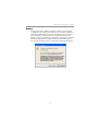
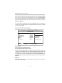
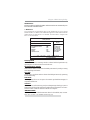
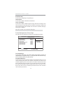
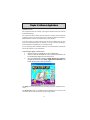
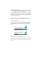
Notice:
1 Owing to Microsoft’s certifying schedule is various to every supplier,
we might have some drivers not certified yet by Microsoft. Therefore, it
might happen under Windows XP that a dialogue box (shown as below)
pop out warning you this software has not passed Windows Logo
testing to verify its compatibility with Windows XP. Please rest assured
that our RD department has already tested and verified these drivers.
Just click the “Continue Anyway” button and go ahead the installation.

1
Chapter 1: Introduction
Chapter 1 Introduction
LGA775 Socket Processor
• Supports the latest Intel
®
Core
TM
2 Duo/Pentium
®
Dual-Core/Celeron
®
4xx Series processors
• Supports 1333/1066/800 MHz Front-Side Bus
Key Features
The key features of this motherboard include:
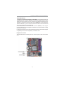
It is a Micro ATX motherboard and has power connectors for an ATX power
supply.
It integrates the G31 Northbridge and ICH7 Southbridge that supports the Serial
ATA interface for high-performance and mainstream desktop PCs; the built-in
USB 2.0 providing higher bandwidth, implementing USB 2.0 EHCI. It supports
High Definition Audio Codec and provides Ultra DMA 100/66/33 function. It
has one PCI Expressx16, one PCI Expressx1 and one 32-bit PCI slot. There is a
full set of I/O ports including two PS/2 ports for mouse and keyboard, one VGA
port, one LAN port, four back-panel USB 2.0 ports and Audio jacks for micro-
phone, line-in and line-out and onboard USB headers providing extra ports by
connecting the Extended USB Module to the motherboard.
This motherboard has a LGA775 socket for latest Intel
®
Core
TM
2 Duo/Pentium
®
Dual-Core/Celeron
®
4xx Series processors with Front-Side Bus (FSB) speeds
up to 1333/1066/800 MHz.

2
Motherboard User’s Guide
Serial ATA
•
Serial ATA Connector
• Transfer rate exceeding best ATA (3.0 Gb/s) with scalability to higher
rates
• Low pin count for both host and devices
Onboard IDE channels
• One IDE Connector
• Supports PIO (Programmable Input/Output) and DMA (Direct Memory
Access) modes
• Supports IDE Ultra DMA bus mastering with transfer rates of 100/66/
33 MB/sec
Expansion Slots
• One 32-bit PCI slot
• One PCI Express x16 slot
• One PCI Express x1 slot
Memory Support
• Two 240-pin DIMM sockets for DDR2 SDRAM with Dual-channel
architecture
• Supports DDR2 800/667 memory bus
• Maximum installed memory is 4 GB
• System Memory Controller Support: DDR2 SDRAM with up to
maximum memory of 4 GB.
• PCI Express Graphics Interface Support: One PCI Express x16 port
• PCI Bus Interface Support: PCI Revision 2.3 Specification at 33MHz
• Integrade Serial ATA Host Controller with Data transfer rates up to 3.0
Gb/s
• Intgrated IDE Controller: Ultra DMA-100/66/33 Bus Master EIDE
Controller
• USB 2.0: Integrated USB 2.0 interface, supporting up to six functional
ports
• High Performance Host Interface: Supports Intel
®
Core
TM
2 Duo/
Pentium
®
Dual-Core/Celeron
®
4xx Series processor family with
FSB1333 MHz
Chipset
There are G31 Northbridge and ICH7 Southbridge in the chipsets in accordance
with an innovative and scalable architecture with proven reliability and perfor-
mance.

3
Chapter 1: Introduction
Onboard I/O Ports
• Two PS/2 ports for mouse and keyboard
• One VGA port
• One LAN port
• Four back-panel USB2.0 ports
• Audio jacks for microphone, line-in and line-out
BIOS Firmware
This motherboard uses AMI BIOS that enables users to configure many system
features including the following:
• Power management
• Wake-up alarms
• CPU parameters
• CPU and memory timing
The firmware can also be used to set parameters for different processor clock
speeds.
Note: Hardware specifications and software items are subject to change
without notification.
Dimensions
• Micro ATX form factor of 225 x 170 mm
Audio
• 5.1 Channel High Definition Audio Codec
• Exceeds Microsoft Windows Logo Program (WLP) Requirements
• ADCs support 44.1K/48K/96K/192KHz sample rate
• High Quality Differential CD input
• Power Support: Digital: 3.3V; Analog: 5.0V
LAN
• Supports 10/100 Mbps Ethernet Transceiver
• Fully compliant with IEEE802.3, IEEE802.3u, IEEE802.3ab
• Wake-On-LAN (WOL) by Magic Packet/Frame/Link Change

4
Motherboard User’s Guide
Package Contents
Your motherboard package ships with the following items:
The motherboard
The User’s Guide
One IDE drive ribbon cable
The Software support CD
Optional Accessories
You can purchase the following optional accessories for this
motherboard.
The Extended USB module
The Serial ATA cable
The Serial ATA power cable
Note: You can purchase your own optional accessories from the third party,
but please contact your local vendor on any issues of the specification
and compatibility.

5
Chapter 2: Motherboard Installation
Chapter 2 Motherboard Installation
To install this motherboard in a system, please follow these instructions in this
chapter:
Identify the motherboard components
Install a CPU
Install one or more system memory modules
Make sure all jumpers and switches are set correctly
Install this motherboard in a system chassis (case)
Connect any extension brackets or cables to headers/connectors on the
motherboard
Install peripheral devices and make the appropriate connections to
headers/connectors on the motherboard
Note:
1. Before installing this motherboard, make sure jumper CLR_CMOS is
under Normal setting. See this chapter for information about locating
CLR_CMOS and the setting options.
2. Never connect power to the system during installation; otherwise, it
may damage the motherboard.

6
Motherboard User’s Guide
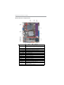
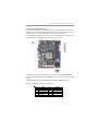
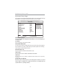
Motherboard Components
LABEL COMPONENTS
LGA775 socket for Intel
®
Core
™
2 Duo/
Pentium
®
Dual-Core/Celeron
®
4xx Series processors
2. CPU_FAN
CPU cooling fan connector
3. DDR2_1~2
240-pin DDR2 SDRAM slots
4. ATX_POWER
Standard 24-pin ATX power connector
5. IDE
Primary IDE channel
6. SPK
Speaker header
7. CLR_CMOS
Clear CMOS jumper
8. F_PANEL
Front Panel switch/LED header
9. F_USB
Front Panel USB header
10. SATA1~2
Serial ATA connectors
11. LPT
Onboard parallel port header
12. F_AUDIO
Front panel audio header
13. PCI1
32-bit add-on card slot
14. CO
M
Onboard serial port header
15. PCIE
PCI Express x1 slot
16. PCIEX16
PCI Express x16 graphics card slot
Rear Panel USB PS/2 Power Select Jumper (for PS/2
S3 wake-up only)
18. ATX12
V
4-pin +12V power connector
1. CPU Socket
17. KBMPWR

7
Chapter 2: Motherboard Installation
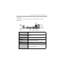
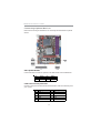
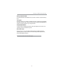
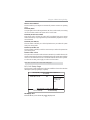
I/O Ports
The illustration below shows a side view of the built-in I/O ports on the
motherboard.
PS/2 Mouse
Use the upper PS/2 port to connect a PS/2 pointing
device.
PS/2 Keyboard
Use the lower PS/2 port to connect a PS/2
keyboard.
VGA Port
Use the VGA port to connect VGA devices.
LAN Port
Connect an RJ-45 jack to the LAN port to connect
your computer to the Network.
USB Ports
Use the USB ports to connect USB devices.
Audio Ports
Use these three audio jacks to connect audio
devices. The first jack is for stereo Line-In signal,
the second jack for stereo Line-Out signal, and the
third jack for Microphone.

8
Motherboard User’s Guide
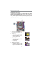
Installing the Processor
This motherboard has a LGA775 socket for the latest Intel
®
Core
TM
2 Duo/
Pentium
®
Dual-Core/Celeron
®
4xx Series processors. When choosing a pro-
cessor, consider the performance requirements of the system. Performance is based
on the processor design, the clock speed and system bus frequency of the proces-
sor, and the quantity of internal cache memory and external cache memory.
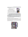
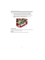
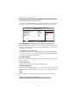
CPU Installation Procedure
Follow these instructions to install the CPU:
B. Unload the cap
• Use thumb & forefinger to hold the
lifting tab of the cap.
• Lift the cap up and remove the cap
completely from the socket.
C. Open the load plate
• Use thumb & forefinger to hold the
hook of the lever, pushing down and
pulling aside unlock it.
• Lift up the lever.
• Use thumb to open the load plate.
Be careful not to touch the contacts.
D. Install the CPU on the socket
• Orientate CPU package to the socket.
Make sure you match triangle marker
to pin 1 location.
A. Read and follow the instructions
shown on the sticker on the CPU cap.

9
Chapter 2: Motherboard Installation
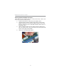
E. Close the load plate
• Slightly push down the load plate onto
the tongue side, and hook the lever.
• CPU is locked completely.
F. Apply thermal grease on top of the CPU.
G. Fasten the cooling fan supporting base
onto the CPU socket on the motherboard.
H. Make sure the CPU fan is plugged to the CPU
fan connector. Please refer to the CPU cooling fan
user’s manual for mor detail installation procedure.
Installing Memory Modules
This motherboard accommodates two 240-pin DIMM sockets for unbuffered DDR2
800/667 memory modules, and maximum 4 GB installed memory.
Over its predecessor, DDR-SDRAM, DDR2-SDRAM offers greater bandwith
and density in a smaller packahe along with a reduction in power consumption. In
addition, DDR2-SDRAM offers new features and functions that enable a higher
clock rate and data rate operations of 667 MHz, 800 MHz. DDR2 transfer 64 bits
of data twice every clock cycle.
Note 1: To achieve better airflow rates and heat dissipation, we suggest that
you use a high quality fan with 3800 rpm at least. CPU fan and
heatsink installation procedures may vary with the type of CPU fan/
heatsink supplied. The form and size of fan/heatsink may also vary.
Note 2: The fan connector supports the CPU cooling fan of 1.1A~2.2A (26.4W
max.) at +12V.
Note 3: Do Not remove the CPU cap from the socket before installing a CPU.
Note 4: Return Material Authorization (RMA) requests will be accepted only if
the motherboard comes with the cap on the LGA775 socket.

10
Motherboard User’s Guide
Memory Module Installation Procedure
These modules can be installed with up to 4 GB system memory. Refer to the
following to install the memory module.
1. Push down the latches on both sides of the DIMM socket.
2. Align the memory module with the socket. There is a notch on the
DIMM socket that you can install the DIMM module in the correct
direction. Match the cutout on the DIMM module with the notch on
the DIMM socket.
3. Install the DIMM module into the socket and press it firmly down
until it is seated correctly. The socket latches are levered upwards and
latch on to the edges of the DIMM.
4. Install any remaining DIMM modules.

11
Chapter 2: Motherboard Installation
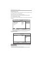
Table A: DDR2 (memory module) QVL (Qualified Vendor List)
The following DDR2 800/667 memory modules have been tested and qualified for use
with this motherboard.
Type Size Vendor Module Name
Apacer 78.91G92.9K5
Micron MT4HTF6464AY-667E1
PSC AL6E8E63J-6E1
Ramxel RML1520M38D6F-667
512 MB
Samsung PC2-5300U-555-12-D3
AU01GE667C5KBGC
78.01G9O.9K5
Apacer
1GB UNB PC2-5300 CL5
Corsair VS1GB667D2
Hexon HYNT7AUDR-30M48
Kingston KVR667D2N5
Micron MT8HTF12864AY-667E1
AL7E8E63B-6E1T
AL7E8F63J-6E1
PSC
AL7E8F73C-6E1
1 GB
Samsung GOLD BAR M378T2863DZS 0742
Aeneon AET860UD00-30DB08X
Apacer 78.A1G9O.9K4
Hynix HYMP125U64AP8-Y5 AB-A 0623
Hexon HYNT8AUDR-30M88
Kingston KVR667D2N5/2G
LeadMax PC2-5300U
PSC AL8E8F73C-6E1
2 GB
Qimonda HYS64T256020EU-3S-C2
DDR2 667
4 GB
Aeneon AET960UD00-30D

12
Motherboard User’s Guide
Type Size Vendor Module Name
Kingston
KVR800D2N5/512 1.8V 9905315-
019.A02LF
Micron MT8HTF6464AY-80ED4
512 MB
Qimonda HYS72T64000HU-2.5-B
A-DATA M2GVD6G3I41P0U1E5E
AET760UD00-30DB97X
Aeneon
AET760UD00-25DC08X
AU01GE800C5KBGC
Apacer
78.01GAO.9K5
APOGEE AU1G082-800P000
Geil GEIL MILLENARY
Hexon ELPT7AUDR-25M48
Infinity 04701G16CZ5U2G
Kingston
KVR800D2N5/1G 1.8V 9905316-
054.A01LF
Nanya NT1GT64U88D0BY-AD
PSC AL7E8F73C-8E1
Ramaxel RML1320EH38D7F-800
GOLD BAR M378T2953EZ3-CE7 0726
Samsung
M378T2863EHS-CF7 0849
Silicon Power SP001GBLRU800S01
Transcend 507301-1571
1 GB
Unifosa GU341G0ALEPR6B2C6CE
A-DATA RED A-DATAM2OMI6H3J4720L1C5Z
Aeneon AET860UD00-25DC08X
Apacer 78.A1GAO.9K4
CORSAIR CM2X2048-6400C5
Geil
PLATINUM
EDITION/Geil/BOXED/2GB/DS
Hexon ELPT8AUDR-25M88
KVR800D2N6/2G-SP
Kingston
KVR800D2N5/2G
Micron MT16HTF25664AY-800E1
Nanya NT2GT64U8HD0BY-AD
PSC AL8E8F73C-8E1
Qimonda HYS64T256020EU-25F-C2
Samsung M378T5663QZ3-CF7
Silicon Power SP002GBLRU800S01
Samsung M378T5663EH3-CF7 0849
2 GB
Unifosa GU342G0ALEPR692C6CE
Aeneon AET960UD00-25D
DDR2 800
4 GB
Samsung M378T5263AZ3-CF7 0819
Aeneon AXT760UD00-19DC97X//7/1GB
Infinity 04701G16CY5U2A
DDR2 1066 1 GB
OCZ OCZ2RPR10662GK
Users please note that: According to Intel G31 Chipset
Specification, the frequency of memory will downgrade to 800 MHz
when using DDR2 1066.

13
Chapter 2: Motherboard Installation
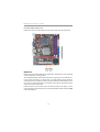
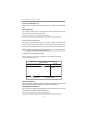
Jumper Settings
Connecting two pins with a jumper cap is SHORT; removing a jumper cap from
these pins, OPEN.
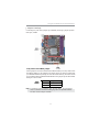
CLR_CMOS: Clear CMOS Jumper
Use this jumper to clear the contents of the CMOS memory. You may need to clear
the CMOS memory if the settings in the Setup Utility are incorrect and prevent
your motherboard from operating. To clear the CMOS memory, disconnect all the
power cables from the motherboard and then move the jumper cap into the CLEAR
setting for a few seconds.
Function Jumper Setting
Normal Short Pins 1-2
Clear CMOS Short Pins 2-3
Note: To avoid the system unstability after clearing CMOS, we recommend
users to enter the main BIOS setting page to “Load Optimal Defaults”
and then “Save Changes and Exit”.
CLR_CMOS
1

14
Motherboard User’s Guide
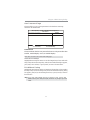
1. Make sure the power supply provides enough SB5V voltage before
selecting the SB5V function.
2. To wake up the computer by USB/PS2 KB/Mouse in S3 status, users
have to place the KBMPWR cap onto 2-3 pin instead of 1-2 as default,
and then press into BIOS “Power Management Setup” page to choose
the functions (USB/PS2KB/MS) you want to enable.
KBMPWR: Rear USB PS/2 Power Select Jumper (for PS/2 S3 wakeup
only)
KBMPWR
1
Function Jumper Setting
VCC Short Pins 1-2
5VSB Short Pins 2-3
Notes:

15
Chapter 2: Motherboard Installation
Pin Signal Pin Signal
1 HD_LED_P(+) 2 FP PWR/SLP(+)
3 HD_LED_N(-) 4 FP PWR/SLP(-)
5 RESET_SW_N( - ) 6 POWER_SW_P( +)
7 RESET_SW_P( +) 8 POWER_SW_N( - )
9 RSV D_DNU 10 KEY
Here is a list of the F_PANEL pin assignments.
Install the Motherboard
Install the motherboard in a system chassis (case). The board is a Micro ATX size
motherboard. You can install this motherboard in an ATX case. Make sure your
case has an I/O cover plate matching the ports on this motherboard.
Install the motherboard in a case. Follow the case manufacturer’s instructions to
use the hardware and internal mounting points on the chassis.
Connect the power connector from the power supply to the ATX_POWER
connector on the motherboard. The ATX12V is a +12V connector for CPU Vcore
power.
Connect the case switches and indicator LEDs to the F_PANEL header.

16
Motherboard User’s Guide
Pin Signal Pin Signal
1VCC2Key
3 NC 4 Signal
Connecting Optional Devices
Refer to the following for information on connecting the motherboard’s optional
devices:
SPK: Speaker Header
Connect the cable from the PC speaker to the SPK header on the motherboard.
Pin Signal Pin Signal
1 DCDB 2 SINB
3SOUTB 4DTRB
5GND 6DSRB
7RTSB 8CTSB
9RI 10KEY
COM: Onboard serial port header
Connect a serial port extension bracket to this header to add a second serial port to
your system.

17
Chapter 2: Motherboard Installation
F_AUDIO: Front Panel Audio Header
This header allows the user to install auxiliary front-oriented microphone and line-
out ports for easier access.
Pin Signal Pin Signal
1PORT1L 2GND
3 PORT1 R 4 PRESENCE#
5 PORT2R 6 Sense1_return
7 SENSE_SEND 8 KEY
9PORT2L 10Sense2_return
Pin Signal Pin Signal
1USBPWR0 2USBPWR1
3 USB_FP_ P0( - ) 4 USB_FP_ P1( - )
5 USB_FP_P0(+) 6 USB_FP_P1(+)
7 GROUND 8 GROUND
9KEY 10NC
1. Locate the F_USB header on the motherboard.
2. Plug the bracket cable onto the F_USB header.
3. Remove a slot cover from one of the expansion slots on the system
chassis. Install an extension bracket in the opening. Secure the extension
bracket to the chassis with a screw.
F_USB: Front panel USB Header
The motherboard has four USB ports installed on the rear edge I/O port array.
Additionally, some computer cases have USB ports at the front of the case. If you
have this kind of case, use auxiliary USB header F_USB to connect the front-
mounted ports to the motherboard.
LPT: Onboard parallel port Header
This header allows the user to connect to the printer, scanner or devices.
Pin Signal Pin Signal
1STROBE 2PD0
3 PD1 4 PD2
5 PD3 6 PD4
7 PD5 8 PD6
9PD7 10ACK
11 BUSK 12 PE
13 SLCT 14 ALF
15 ERROR 16 INIT
17 SLCTIN 18 Ground
19 Ground 20 Ground
21 Ground 22 Ground
23 Ground 24 Ground
25 Ground 26 Key
Page is loading ...
Page is loading ...
Page is loading ...
Page is loading ...
Page is loading ...
Page is loading ...
Page is loading ...
Page is loading ...
Page is loading ...
Page is loading ...
Page is loading ...
Page is loading ...
Page is loading ...
Page is loading ...
Page is loading ...
Page is loading ...
Page is loading ...
Page is loading ...
Page is loading ...
Page is loading ...
Page is loading ...
-
 1
1
-
 2
2
-
 3
3
-
 4
4
-
 5
5
-
 6
6
-
 7
7
-
 8
8
-
 9
9
-
 10
10
-
 11
11
-
 12
12
-
 13
13
-
 14
14
-
 15
15
-
 16
16
-
 17
17
-
 18
18
-
 19
19
-
 20
20
-
 21
21
-
 22
22
-
 23
23
-
 24
24
-
 25
25
-
 26
26
-
 27
27
-
 28
28
-
 29
29
-
 30
30
-
 31
31
-
 32
32
-
 33
33
-
 34
34
-
 35
35
-
 36
36
-
 37
37
-
 38
38
-
 39
39
-
 40
40
-
 41
41


PC CHIPS P47G (V1.0) User guide
- Category
- Motherboards
- Type
- User guide
Ask a question and I''ll find the answer in the document
Finding information in a document is now easier with AI
Related papers
-
PC CHIPS P29G (V1.0) User guide
-
-
PC CHIPS P53G (V1.0) User manual
-
-
ECS P49G (V1.0) User manual
-
-
-
-
-