Page is loading ...


MGL Avionics Stratomaster Ultra “L” Owner’s manual
Page 2
THE STRATOMASTER ULTRA ..................................................................................................................... 5
SPECIFICATIONS:......................................................................................................................................... 6
GENERAL SPECIFICATIONS.................................................................................................................................................... 6
TECHNICAL SPECIFICATIONS..................................................................................................................... 7
ALTIMETER .......................................................................................................................................................................... 7
AIRSPEED INDICATOR ........................................................................................................................................................... 7
VSI..................................................................................................................................................................................... 7
REV COUNTER ..................................................................................................................................................................... 7
FUEL FLOW SENDER INPUT.................................................................................................................................................... 7
EXTERNAL TEMPERATURE PROBE .......................................................................................................................................... 7
NTC TEMPERATURE SENDER INPUTS..................................................................................................................................... 8
THERMOCOUPLE TEMPERATURE SENDER INPUTS.................................................................................................................... 8
FUEL LEVEL SENDER INPUT ................................................................................................................................................... 9
POWER SUPPLY ................................................................................................................................................................... 9
THE STRATOMASTER ULTRA “L” FEATURES AND FUNCTIONS............................................................9
BASIC SYSTEM FUNCTIONS ................................................................................................................................................... 9
RDAC EIS FUNCTIONS ...................................................................................................................................................... 10
OTHER FUNCTIONS ............................................................................................................................................................ 10
FLIGHT LOG OR LESSON LOG............................................................................................................................. 11
AIRCRAFT REGISTRATION NUMBER................................................................................................................... 18
ALTITUDE ALARM.................................................................................................................................................. 19
TEMPERATURE ALARMS...................................................................................................................................... 19
SPEED LOW ALARM.............................................................................................................................................. 19
SPEED HIGH ALARM (OVER SPEEDING ALARM) ............................................................................................... 20
SAFE SPEED ARC DISPLAY .................................................................................................................................20
FUEL LOW ALARM................................................................................................................................................. 21
INSTRUCTOR MODE ............................................................................................................................................. 21
LESSON TIMER MODE.......................................................................................................................................... 23
LESSON START/END MODE................................................................................................................................ 24
LESSON MANUAL OR AUTOMATIC START/STOP............................................................................................... 24
MASTER OR SLAVE .............................................................................................................................................. 24
TAKE-OFF DISTANCE............................................................................................................................................ 24
DISPLAY BLANKING .............................................................................................................................................. 26
DISPLAY BACKLIGHT............................................................................................................................................ 27
THE MAIN DISPLAY – A DETAILED LOOK................................................................................................ 27
THE ALTIMETER ................................................................................................................................................................. 28
THE AIR SPEED INDICATOR ................................................................................................................................................. 28
THE VSI INDICATOR ........................................................................................................................................................... 29
AUXILIARY FLIGHT INFORMATION ......................................................................................................................................... 29
DENSITY ALTITUDE .............................................................................................................................................. 29
BAROMETER ......................................................................................................................................................... 29
TIME ....................................................................................................................................................................... 30
FLIGHT ................................................................................................................................................................... 30
GCR........................................................................................................................................................................ 30
TEMP...................................................................................................................................................................... 30
DIST........................................................................................................................................................................ 30
VOLT ...................................................................................................................................................................... 31
RANGE ................................................................................................................................................................... 31
BINGO .................................................................................................................................................................... 31
VOLT ...................................................................................................................................................................... 31
STW........................................................................................................................................................................ 32
HOBBS METER...................................................................................................................................................... 32
MAINTENANCE METER......................................................................................................................................... 32
FUEL LEVEL INDICATOR....................................................................................................................................................... 34
THE FUEL FLOW METER ...................................................................................................................................................... 34
THE REV COUNTER............................................................................................................................................................. 35
EIS PANEL DISPLAY ........................................................................................................................................................... 35
COMBINED OIL TEMPERATURE AND OIL PRESSURE INDICATOR............................................................................................... 36
WATER TEMPERATURE INDICATOR....................................................................................................................................... 37
OIL PRESSURE INDICATOR (WITHOUT OIL TEMPERATURE) ...................................................................................................... 37
OIL TEMPERATURE INDICATOR (WITHOUT OIL PRESSURE INDICATOR)...................................................................................... 38
EGT AND CHT THERMOCOUPLE DISPLAY ............................................................................................................................ 38
USER MENU................................................................................................................................................. 39
DATE AND TIME .................................................................................................................................................................. 39

MGL Avionics Stratomaster Ultra “L” Owner’s manual
Page 3
HOBBS METER ................................................................................................................................................................... 40
MAINTENANCE METER ........................................................................................................................................................ 40
AIRCRAFT REGISTRATION ................................................................................................................................................... 40
ALTITUDE ALARM................................................................................................................................................................ 40
SPEED LOW ALARM ............................................................................................................................................................ 40
SPEED HIGH ALARM............................................................................................................................................................ 40
CHECKLIST ........................................................................................................................................................................ 41
DEVICE SETUP MENU................................................................................................................................. 42
BASIC SETUP MENU ............................................................................................................................................................ 42
MODE SETUP MENU............................................................................................................................................................ 42
ENGINE TYPE QUICK SELECT ............................................................................................................................................... 42
ENGINE DETAIL SETUP MENU............................................................................................................................................... 42
SENDER SETUP MENU......................................................................................................................................................... 43
FUEL TANK/LEVEL SENDER SETUP ....................................................................................................................................... 43
TECHNICAL ITEMS .............................................................................................................................................................. 43
THE BASIC DEVICE SETUP MENU ............................................................................................................ 44
AIRSPEED CALIBRATION...................................................................................................................................................... 44
ZERO ASI AND VSI ............................................................................................................................................................ 45
ALTIMETER CALIBRATION .................................................................................................................................................... 45
FUEL FLOW CALIBRATION .................................................................................................................................................... 46
REV SETUP: PULSES PER 10 REVS ...................................................................................................................................... 46
TAKE-OFF REVS ................................................................................................................................................................. 46
HOBBS REVS ..................................................................................................................................................................... 46
FUEL LOW ALARM............................................................................................................................................................... 47
BACK LIGHT ....................................................................................................................................................................... 47
ASI SCALE ........................................................................................................................................................................ 47
RPM SCALE ...................................................................................................................................................................... 47
FUEL FLOW SCALE.............................................................................................................................................................. 47
THE MODE SETUP MENU ........................................................................................................................... 48
ALTITUDE .......................................................................................................................................................................... 48
QNH................................................................................................................................................................................. 48
DISTANCE ......................................................................................................................................................................... 48
FUEL................................................................................................................................................................................. 49
TEMPERATURE .................................................................................................................................................................. 49
OIL PRESSURE .................................................................................................................................................................. 49
AMBIENT TEMPERATURE SENDER ........................................................................................................................................ 49
FUEL FLOW SENDER ........................................................................................................................................................... 49
FUEL LEVEL SENDER .......................................................................................................................................................... 50
HOUR FRACTION MODE....................................................................................................................................................... 50
FLIGHT DETECT MODE ........................................................................................................................................................ 50
RESET AIR DISTANCE.......................................................................................................................................................... 50
INSTRUCTOR MODE ............................................................................................................................................................ 50
LESSON START .................................................................................................................................................................. 50
AUTOMATIC LESSON START/END ......................................................................................................................................... 51
AIRTALK ............................................................................................................................................................................ 51
CHECKLIST ........................................................................................................................................................................ 51
ENGINE TYPE QUICK SELECT................................................................................................................... 51
ENGINE DETAIL SETUP MENU .................................................................................................................. 52
SENDER TYPE SELECTION ................................................................................................................................................... 53
FUEL TANK/LEVEL SENDER SETUP......................................................................................................... 55
CARING FOR THE STRATOMASTER ULTRA............................................................................................ 57
PITOT TUBE ....................................................................................................................................................................... 57
CLEANING ......................................................................................................................................................................... 57
CALIBRATION ..................................................................................................................................................................... 57
ALTIMETRY.................................................................................................................................................. 57
TRUE AIRSPEED (TAS)............................................................................................................................... 59
WARRANTY.................................................................................................................................................. 60
DISCLAIMER ................................................................................................................................................ 60

MGL Avionics Stratomaster Ultra “L” Owner’s manual
Page 4
INSTALLATION MANUAL FOR THE STRATOMASTER ULTRA “X” ........................................................62
INTRODUCTION .................................................................................................................................................................. 62
POWER SUPPLY CONNECTIONS ........................................................................................................................................... 63
AMBIENT TEMPERATURE SENDER ........................................................................................................................................ 64
EXTERNAL, VISUAL ALARM INDICATOR.................................................................................................................................. 65
EXTERNAL, AUDIBLE ALARM ................................................................................................................................................ 66
PITOT TUBE AND STATIC PORT............................................................................................................................................. 67
CONNECTING THE RDAC IV EIS......................................................................................................................................... 69
RDAC EIS UNIT THERMOCOUPLE INPUTS ............................................................................................................................ 70
THERMOCOUPLE INPUTS – DETAILS ..................................................................................................................................... 70
RDAC FUEL FLOW SENDER INSTALLATION ........................................................................................................................... 72
CONNECTING A FUEL LEVEL SENDER.................................................................................................................................... 75
CONNECTING A ROTAX 912 ................................................................................................................................................ 77
CONNECTING A ROTAX 503 ................................................................................................................................................ 78
CONNECTING A ROTAX 503 ................................................................................................................................................ 78
CONNECTING A ROTAX 582 ................................................................................................................................................ 78

MGL Avionics Stratomaster Ultra “L” Owner’s manual
Page 5
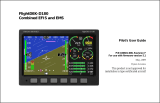
The Stratomaster Ultra
A typical setup including Rotax 582 EIS (engine information system)
The Stratomaster Ultra “L” is a digital multifunction instrument designed for use in ultralight,
microlight, experimental and homebuilt aircraft as well as any aircraft that permit use of such
instrumentation under general or special operating permits.
Most civil aviation authorities permit installation of this type of instrument as a secondary
instrument on certified aircraft. Please ensure that you obtain the required permits or STCs
before operating this instrument on a certified aircraft.
The Stratomaster Ultra includes a remote EIS (Engine information system) called RDAC
(Remote Data Acquisition Computer) in addition to a full future primary flight information
system (PFIS). The Stratomaster Ultra brings glass cockpit functionality to small aircraft,
replacing unreliable and expensive analogue dials while extending the functions normally
available to include fuel and flight management items amongst many other useful features.
The Stratomaster Ultra further reduces empty weight of an aircraft and simplifies
instrumentation installation to an incredible degree as only a single wire is required between
the RDAC and the display unit. All engine related probes and wires terminate in the RDAC
unit which is to be located in the engine compartment. This practically eliminates costly and
unpractical wiring while offering benefits such as improved electrical noise immunity.
The Stratomaster Ultra has been designed with the following objectives in mind:
a) Provide a cost effective solution for a complete instrumentation system for small aircraft.
b) Provide instrumentation with uncompromising accuracy and range.
c) Provide a display unit with a shape and form factor suitable for installation into most small
aircraft panels and pods.

MGL Avionics Stratomaster Ultra “L” Owner’s manual
Page 6
d) Provide a display with the best possible viewing qualities over a wide temperature range,
taking into account operation in bright sunlight as well as low light conditions.
e) Provide a system that offers long term stability and reliability.
f) Provide a system that is easy to install and that maintains its usefulness should a different
type of engine be installed in the aircraft.
Many of the objectives have been achieved using the latest available embedded processing
devices, which result in a drastic reduction of the amount of individual components required.
This has a direct effect on improving reliability and reducing EMI (Electromagnetic
interference), long a bane of digital systems.
For the computer minded: The Stratomaster Ultra and the RDAC unit are programmed using
Embedded Pascal, a powerful and unique development system created by the same people
that designed your Stratomaster instrument! Embedded Pascal, released to the public in
1998 has become a successful development environment used in many countries.
SPECIFICATIONS:
General specifications
Size: 202x135 mm. Mounting depth 95mm (including connectors and wiring). Panel cutout
196x122 mm.
Weight: 980 grams. Excluding external senders, including RDAC unit.
Power supply requirements: 12V DC nominal. Range 7.5V DC to 18V DC. Internally
protected to 40 V DC.
Current consumption: 80 mA without back light, 280 mA with back light.
(includes current consumption of RDAC EIS unit)
Rev counter input: High impedance. Accepts signals up to 100V RMS.
Maximum frequency 10 Khz. Internally protected against over voltage.
External temperature sensor input: Optimized for National Semiconductor LM335
temperature sender.
Fuel flow sender connection: Optimized for RS 256-225 flow sender. Will accept other
senders with a 5 volt TTL output.
Engine temperature senders:
Thermocouple inputs for K or J type senders.
NTC inputs for Rotax senders and MGL senders (standard automotive senders).
Accepts MGL precision semiconductor senders for water and oil temperature (optional items)
Fuel level sender: Optimized for standard automotive level senders from 100 to 500 ohms
resistance, any slope (increasing resistance with level or decreasing resistance with level).
Alarm contacts: Uncommitted reed relay output. Recommended not to exceed 500 mA DC
current. Maximum voltage 50 volts. Please note: heavy inductive loads must be protected by
means of a reverse polarity diode in order to prevent sparks from destroying the reed relay
contacts.
Air-talk link: Two Air-talk links are provided. These are used to connect to other Air-Talk
compatible devices. Standard audio RCA cable and connectors are used as medium. Air-talk
is intended as a short distance, multi master communications link allowing Air-talk compatible
devices to share information. The Stratomaster Ultra uses the Air-talk link to connect to

MGL Avionics Stratomaster Ultra “L” Owner’s manual
Page 7
another Stratomaster Ultra, Ultra or Flight slave unit, a PC, Flight data recorder (black box),
and key download devices (for transfer of the log to a remote PC).
Technical specifications
Altimeter
Range 0-40 000 ft (12 195 m), 1ft (or 1 m) dynamic resolution, 7.5 ft (or 2 m) static resolution
at sea level. Dynamic resolution applies with the aircraft in flight. Dynamic resolution is
measured by mathematically evaluating the turbulence created around the aircraft.
Basic accuracy at 20 degrees C (68 degrees F) +/- 30 ft (9 m) based on calibration to
mercury manometer at +/- 1 mb (0.0295 Inch of Hg).
Maximum theoretical error factor +/- 1.5% over temperature range 0-40 degrees C (104
degrees F). Typical error factor over temperature range 0-40 degrees C (104 degrees F) is
less than 0.5%
Note: The altimeter can be operated to altitudes above 40 000 ft (12 195 m). Range and
accuracy above the 40 000 ft (12 195 m) level are dependant on individual units. The
achievable range is in the region of 45 000 ft (13 720 m) to 60 000 ft (18 293 m) depending
on manufacturing tolerances of the pressure sensor.
Airspeed indicator
Range 0-200 mph (322 Kph or 174 Knots), 1 mph (1 Kph or 1 Knot) resolution. Theoretical
accuracy 1% at 20 degrees C (68 degrees F), subject to installation of pitot tube and airflow
pattern around aircraft.
Versions for higher airspeeds are available at reduced low speed sensitivity.
VSI
Range +/- 9 990 ft. (3 045 m) Resolution truncated to 10 ft/minute (5cm per second).
Internally 1 ft/minute. Accuracy +/-5 %, Please note: The VSI is compensated for altitude.
Analogue VSI display is logarithmic providing both very high sensitivity and a wide range.
Minimum display resolution is as low as 10 ft/min (5cm per second) with a +/-2 000 ft (610 m)
maximum reading.
Rev counter
Range 0 to 9 999 revs. Resolution is dependant on rev counter setup in instrument.
Accuracy: +/- 0.0005% + resolution.
Fuel flow sender input
Accuracy of measurement is +/-0.05% subject to accuracy of fuel flow sender used. Example
sender is RS 256-225: +/- 3% uncalibrated, typically less than 1% calibrated.
External temperature probe
Display resolution 1 degree C or 1 degree F. Accuracy 0.5 degrees typical. Range –50 to
+99 degrees C (-58 degrees F - 210 degrees F).

MGL Avionics Stratomaster Ultra “L” Owner’s manual
Page 8
NTC temperature sender inputs
Measurement accuracy +/- 2% subject to accuracy of sender. Note: Senders are
manufactured with a tolerance of up to +/- 20%.
Thermocouple temperature sender inputs
Measurement accuracy +/- 1%. The thermocouple amplifier system used is highly stable and
long-term drift elimination is achieved by using a chopper stabilized system. The system
employed features full, accurate cold junction compensation and bow voltage correction. The
system is further highly immune to received EMI from high powered radio transmitters.

MGL Avionics Stratomaster Ultra “L” Owner’s manual
Page 9
Fuel level sender input
Measurement accuracy of input: +/-2%. Overall measurement accuracy of fuel level is subject
to quality and installation of chosen fuel level sender as well as complexity and form of tank
shape.
Using the prescribed calibration procedure we find we can calibrate within 5% of actual level
for most tank shapes.
Power supply
The Stratomaster Ultra unit is optimized and intended for operation on a 12V DC supply such
as a motorcycle battery. However, it can be operated on any power supply down to about 7
volts as well as aircraft power supplies of 24 or 28V DC.
For high voltage power supplies (above 18V) MGL Avionics recommends the installation of a
pre-regulator to reduce heat build up in the instrument. Such a pre-regulator is inexpensive
and only needs to provide a maximum current of ½ ampere. Please contact your supplier or
MGL Avionics on further details is required.
Current consumption may vary slightly between units but is typically in the region of 80 mA
without display back light and 280 mA with display back light. Please note that when
connecting external sensors such as the fuel level sender, this is supplied from the unit and
the current consumption of the sender has to be added to the consumption of the basic unit.
The above figures include the current needs of the RDAC EIS unit.
The unit is internally protected against temporary over voltage loads such as those that can
be produced by a cranking starter motor.
It is advisable to power the unit via a fuse or circuit breaker. A fuse rating of 1A (slow blow) is
recommended. Generally it is accepted to use circuit breakers that can be reset during flight
should the need arise. Ordinary fuses are not recommended for aircraft use.
The Stratomaster Ultra “L” features and functions
Basic system functions
•=Altitude to 40 000 ft (12 195 m) calibrated, 1ft dynamic resolution
•=Airspeed ASI analog and digital, TAS digital
•=Stopwatch
•=Glide and climb ratio to 1/99
•=QNH 960 to 1 060 mb (28.3 - 31.3 Inch of Hg)
•=QNE 1013 mb quick select (29.9 Inches of Hg)
•=Time of day, Date for flight log entries
•=Air time since take-off (or lesson time)
•=Ambient temperature using external sensor
•=Fuel level using flow sender or optional level sender
•=Fuel flow using optional flow sender
•=Current range estimate (range at current speed and fuel burn)
•=Fuel bingo estimate (time until tank empty)
•=Air distance made good
•=Voltage. Supply to unit. Usually 12V battery.
•=VSI +/- 9 990 ft/minute (50.7 meters per second) range with logarithmic analogue
display

MGL Avionics Stratomaster Ultra “L” Owner’s manual
Page 10
•=Vario output for glider or motor glider use
•=Flight log (or lesson log) storing up to 240 entries
•=User programmable pre-takeoff checklist
•=Hobbs meter, presetable to current engine time
•=Density altimeter
•=Barometer for ambient pressure
•=Aircraft registration number display
•=Maintenance timer
•=Warnings for engine temperature, speed high, speed low, maximum altitude and
low fuel level
•=Alarm contact output to switch a warning lamp
•=Audio alarm output to drive a panel speaker or low level output for alarm tone
injection into a suitably equipped headset or intercom system.
•=Instructor modes
•=Master and slave modes for dual instrument setup
•=Measuring take-off run to 50 ft (15.24 m) above ground level
•=Air talk link for connection to:
•=A) PC’s and Laptops using optional cable
•=B) Stratomaster “Black Box” flight recorder
•=C) Stratomaster Ultra secondary instrument
•=D) Key ring flight log download device
RDAC EIS functions
•=Four channel thermocouple amplifier, high resolution chopper stabilized system with
full cold junction compensation and bow voltage correction to laboratory standards.
The inputs can accept K-type or J-type thermocouples (selectable via provided menu
functions)
•=Two channel NTC measurement input for Rotax 912 standard CHT senders.
•=Oil or Water temperature NTC input compatible with Rotax oil temperature sender
and MGL water temperature sender. Also accepts MGL precision semiconductor
senders for water and oil temperature.
•=Universal rev counter input. Can be used on a wide variety of engines using a variety
of interface methods.
•=Fuel flow sender input. Can be used with most commercial liquid flow senders.
Calibration via provided menu functions.
•=Oil pressure sender input. Accepts most commercial oil pressure senders including
the VDO unit used by Rotax.
•=Fuel level sender input with extensive calibration functions provided to allow direct
readout of fuel quantity corrected for tank shape and sender tolerances.
The EIS included with the Ultra “L” provides for a wide variety of engines and the display unit
can be configured in many different ways as outlined under the “Device setup menu”.
Typical engines range from small single cylinder two strokes, the Rotax series of engines
from the 447, 503, 582, 618 and the four stroke 912 and 914 engines. All of the 2SI (Two-
stroke international) engines can be used as well as many typical automotive engine
conversions, VW, BMW and Subaru being only a few. The EIS is also a perfect fit for the
Australian Jabiru engines and the HKS two cylinder four-strokers.
For larger engines or additional thermocouple channels please have a look at the
“Stratomaster Ultra X” line of instruments.
Other functions

MGL Avionics Stratomaster Ultra “L” Owner’s manual
Page 11
FLIGHT LOG OR LESSON LOG
Perhaps one of the most useful features of the Stratomaster Ultra instrument is the ability to
record a flight log. Using one of several methods, the Stratomaster Ultra will record flight details
suitable for entry into a flight and engine log.
You can setup your Stratomaster Ultra to record a log entry in one of the following ways:
1. Automatic flight log. This will automatically detect the start of a flight and end of a flight.
The unit uses engine revs in combination with airspeed to detect a flight. This is the way
most pilots prefer to operate the Stratomaster Ultra.
2. Manual flight log. In this case the pilot manually starts a flight and ends it. This mode is
used mainly if no rev counter input to the instrument is available.
3. Instructor mode. In this case the log is used to record “lessons” rather than “flights”. A
lesson is started by the instructor or automatically if setup accordingly and lesson time is
accumulated according to the instruments lesson mode setup. A single lesson may
consist of more than one flight.
The Stratomaster Ultra will log all flights/lessons of longer than one minute. Any lessons or flights
with less than one minute accumulated time are not stored in the log.
The Stratomaster Ultra will store the last 224 flights or lessons in the log.
The log can be viewed at any time. Please also note that the log may be downloaded to a PC
using a direct cable connection or key-ring download device (optional extras).
The following information pertaining to a flight/lesson will be logged:
•=Date (DD/MM) of take-off
•=Take-off time or Lesson Start time.
•=Flight or Lesson time. Displayed in either hours and minutes or hours and fraction of
hours depending on setup.
•=Highest altitude reached (In ft or meters depending on setup)
•=Maximum airspeed obtained. Displayed airspeed depends on whether ASI or TAS is
selected. (Displayed in kilometers, miles or knots depending on setup).
•=Hobbs meter reading at end of flight/lesson (Displayed in either hours and minutes or
hours and fraction of hours depending on setup)
•=Student number (Instructor mode only)


MGL Avionics Stratomaster Ultra “L” Owner’s manual
Page 13
Flight log examples
Definition start of flight: The point in time when engine RPM increases above a preset limit
as determined by you (Refer take-off revs page 46), as well as from the time at which the
airspeed increases to above 30 mph, 48 kph or 26 knots.
Definition end of flight: The point in time when the airspeed decreases to below 20 mph,
32 kph or 17 knots for longer than 30 seconds.
Example one:
Stratomaster Ultra setup:
Instructor mode: Normal
Flight detect mode: Automatic
Hour fraction mode: Hour has minutes
Altitude Feet
Distance Miles
Airspeed ASI
Time of day Action
13h06 Increase revs to higher than hobbs revs
13h08 Increase revs to higher than take-off revs
13h09 Airspeed as per start of flight definition
13h29 Airspeed as per end of flight definition
Log results:
T/O 05/07 13:09 00:21
ALT 4636Ft SPD 183mph Hobbs 0155:51
Day/Month Take-off time Duration of flight
Highest altitude Highest airspeed Hobbs reading at end flight
(Note: Take-off revs only determines the start of the flight. Revs for the remainder of the
flight are not taken into account).
Example two:
Stratomaster Ultra setup:
Instructor mode: Normal
Flight detect mode: Automatic
Hour fraction mode: Hour has decimals
Altitude Feet
Distance Miles
Airspeed ASI
Time of day Action
13h06 Increase revs to higher than hobbs revs
13h08 Increase revs to higher than take-off revs
13h09 Airspeed as per start of flight definition
13h29 Airspeed as per end of flight definition
Log results:

MGL Avionics Stratomaster Ultra “L” Owner’s manual
Page 14
T/O 05/07 13:09 00:35
ALT 4636Ft SPD 183mph Hobbs 0155.85
Day/Month Take-off time Duration of flight
Highest altitude Highest airspeed Hobbs reading at end flight
(Note: Take-off revs only determines the start of the flight. Revs for the remainder of the
flight are not taken into account).
Example three:
Stratomaster Ultra setup:
Instructor mode: Normal
Flight detect mode: Manual
Hour fraction mode: Hour has minutes
Altitude Feet
Distance Miles
Airspeed ASI
Time of day Action
12h36 ` Manual input - Start new flight
12h37 Increase revs to higher than hobbs revs
12h41 Increase revs to higher than take-off revs
12h42 Airspeed as per start of flight definition
12h55 Airspeed as per end of flight definition
13h00 Manual input - End current flight
Log results:
T/O 05/07 12:36 00:23
ALT 4636Ft SPD 183mph Hobbs 0155:21
Day/Month Manual start of flight Duration of flight
Highest altitude Highest airspeed Hobbs reading at end flight
(Note: Flight time calculated from manual starting of flight to manual ending of flight).
Lesson Log Examples
Definition: Start of lesson. Such time as the engine revs increases above either hobbs or
take-off revs (Refer lesson start page 23).
Definition: Lesson time. Lesson time accumulates if engine revs are above hobbs revs or if
the aircraft is in flight.
A lesson ends when the "End current lesson" menu item is selected. At this point in time the
lesson details are written to the log.
Example one:
Stratomaster Ultra setup:
Instructor mode: Instructor
Flight detect mode: Automatic
Hour fraction mode: Hour has minutes
Lesson timer mode Hobbs revs
Altitude Feet

MGL Avionics Stratomaster Ultra “L” Owner’s manual
Page 15
Distance Miles
Airspeed ASI
Time of day/Action
16h17 Manual input - Start new lesson (P Flashing)
16h19 Increase revs to higher than hobbs revs (A Flashing)
16h22 Increase revs to higher than take-off revs (A Flashing)
16h25 Airspeed as per start of flight definition
16h31 Decrease revs to lower than take-off revs
16h37 Decrease revs to lower than hobbs revs
16h40 Airspeed as per end of flight definition (A Flashing)
16h45 Manual input - End current lesson
Student number: 1
Log results:
T/O 05/07 16:19 00:21
ALT 4626Ft SPD 166mph Hobbs 0155:21 St 1
Day/Month Time - Start of lesson Duration of lesson
Highest altitude Highest airspeed Hobbs reading Student
(Note: Lesson time calculated from higher than hobbs revs to airspeed as per end of flight
definition e.g. 16h19 - 16h40).
Flashing P = Lesson has been primed
Flashing A = Lesson has been activated
Example two:
Stratomaster Ultra setup:
Instructor mode: Instructor
Flight detect mode: Automatic
Hour fraction mode: Hour has decimals
Lesson timer mode Hobbs revs
Altitude Feet
Distance Miles
Airspeed ASI
Time of day/Action
16h17 Manual input - Start new lesson (P Flashing)
16h19 Increase revs to higher than hobbs revs (A Flashing)
16h22 Increase revs to higher than take-off revs (A Flashing)
16h25 Airspeed as per start of flight definition
16h31 Decrease revs to lower than take-off revs
16h37 Decrease revs to lower than hobbs revs
16h40 Airspeed as per end of flight definition (A Flashing)
16h45 Manual input - End current lesson
Student number: 1
Log results:
T/O 05/07 16:19 00:35
ALT 4626Ft SPD 166mph Hobbs 0155:35 St 1

MGL Avionics Stratomaster Ultra “L” Owner’s manual
Page 16
Day/Month Time - Start of lesson Duration of lesson
Highest altitude Highest airspeed Hobbs reading Student
(Note: Lesson time calculated from higher than hobbs revs to airspeed as per end of flight
definition e.g. 16h19 - 16h40).
Flashing P = Lesson has been primed
Flashing A = Lesson has been activated
Example three:
Stratomaster Ultra setup:
Instructor mode: Instructor
Flight detect mode: Automatic
Hour fraction mode: Hour has minutes
Lesson timer mode Take-off revs
Altitude Feet
Distance Miles
Airspeed ASI
Time of day/Action
16h55 Manual input - Start new lesson (P Flashing)
17h00 Increase revs to higher than hobbs revs (P Flashing)
17h03 Increase revs to higher than take-off revs (A Flashing)
17h04 Airspeed as per start of flight definition
17h11 Decrease revs to lower than take-off revs
17h14 Decrease revs to lower than hobbs revs
17h16 Airspeed as per end of flight definition (A Flashing)
17h20 Manual input - End current lesson
Student number: 2
Log results:
T/O 05/07 17:03 00:13
ALT 4583Ft SPD 200mph Hobbs 0159:08 St 2
Day/Month Time - Start of lesson Duration of lesson
Highest altitude Highest airspeed Hobbs reading Student
(Note: Lesson time calculated from higher than take-off revs to airspeed as per end of flight
definition e.g. 17h03 - 17h16).
Flashing P = Lesson has been primed
Flashing A = Lesson has been activated
Example four:
Stratomaster Ultra setup:
Instructor mode: Instructor
Flight detect mode: Manual
Hour fraction mode: Hour has minutes
Lesson timer mode Hobbs revs
Altitude Feet
Distance Miles
Airspeed ASI

MGL Avionics Stratomaster Ultra “L” Owner’s manual
Page 17
Time of day/Action
17h26 Manual input - Start new flight
17h29 Manual input - Start new lesson
17h31 Increase revs to higher than hobbs revs
17h36 Increase revs to higher than take-off revs
17h38 Airspeed as per start of flight definition
17h45 Decrease revs to lower than take-off revs
17h52 Decrease revs to lower than hobbs revs
17h56 Airspeed as per end of flight definition (A Flashing)
17h58 Manual input - End current flight
18h00 Manual input - End current lesson
Student number: 3
Log results:
T/O 05/07 17:31 00:27
ALT 4572Ft SPD 82mph Hobbs 0159:29 St 3
Day/Month Time - Start of lesson Duration of lesson
Highest altitude Highest airspeed Hobbs reading Student
(Note: Lesson time calculated from higher than hobbs revs to manual ending of flight i.e.
17h31 - 17h58).
Flashing P = Lesson has been primed
Flashing A = Lesson has been activated
Example five:
Stratomaster Ultra setup:
Instructor mode: Instructor
Flight detect mode: Manual
Hour fraction mode: Hour has minutes
Lesson timer mode Take-off revs
Altitude Feet
Distance Miles
Airspeed ASI
Time of day/Action
19h06 Manual input - Start new flight
19h16 Manual input - Start new lesson
19h19 Increase revs to higher than hobbs revs
19h24 Increase revs to higher than take-off revs
19h25 Airspeed as per start of flight definition
19h30 Decrease revs to lower than take-off revs
19h37 Decrease revs to lower than hobbs revs
19h40 Airspeed as per end of flight definition
19h42 Manual input - End current lesson
Student number: 5
(Note: Ending a lesson automatically ends the flight)
Log results:
T/O 05/07 19:24 00:18
ALT 4557Ft SPD 200mph Hobbs 0160:17 St 5

MGL Avionics Stratomaster Ultra “L” Owner’s manual
Page 18
Day/Month Time - Start of lesson Duration of lesson
Highest altitude Highest airspeed Hobbs reading Student
(Note: Flight time calculated from higher than take-off revs to manual ending of lesson e.g.
19h24 - 19h42).
Example six:
Stratomaster Ultra setup:
Instructor mode: Instructor
Flight detect mode: Manual
Hour fraction mode: Hour has minutes
Lesson timer mode Take-off revs
Altitude Feet
Distance Miles
Airspeed ASI
Time of day/Action
16h32 Manual input - Start new flight
16h34 Manual input - Start new lesson
16h37 Increase revs to higher than hobbs revs
16h39 Increase revs to higher than take-off revs
16h40 Airspeed as per start of flight definition
16h45 Decrease revs to lower than take-off revs
16h53 Decrease revs to lower than hobbs revs
16h56 Airspeed as per end of flight definition
16h59 Manual input - End current flight
17h02 Manual input - End current lesson
Student number: 6
Log results:
T/O 06/07 16:39 00:19
ALT4859Ft SPD 85mph Hobbs 0163:41 St 6
Day/Month Time - Start of lesson Duration of lesson
Highest altitude Highest airspeed Hobbs reading Student
(Note: Flight time calculated from higher than take-off revs to manual input end of flight e.g.
16h39 - 16h59).
AIRCRAFT REGISTRATION NUMBER
The Stratomaster Ultra makes 6 digits available for entering the aircraft registration
number (Refer aircraft registration page 40).
The Aircraft registration number will only be displayed at the time the instrument is
switched on.
The registration number or other text you might enter in this field is used to personalize
and identify your instrument. It is used with the key ring download device if you operate
multiple aircraft and would like your log to operate accordingly.

MGL Avionics Stratomaster Ultra “L” Owner’s manual
Page 19
ALTITUDE ALARM
The Stratomaster Ultra will warn you once your aircraft's altitude exceeds a
predetermined level. (Refer altitude alarm page 40) by flashing the altitude display field.
The altitude will remain flashing until the aircraft descends below the predetermined
altitude.
Altitude alarms can be set in increments of 500 ft (152.4m) to a maximum of 60 000 ft
(18 287 m). When setting the alarm all factors should be taken into account. It is the
pilot's responsibility to ensure that the alarm is correctly set prior to take-off.
The altitude alarm can be switched off should you wish not to make use of this function.
(Refer altitude alarm page 40).
An active alarm will result in the Stratomaster Ultra alarm output switching at a rate of
once per second. This is normally used to switch a warning lamp or indicator in the
cockpit. The indicator will flash until the alarm has been acknowledged or the alarm
condition no longer exists. To acknowledge the alarm, press any key. This will switch off
the alarm indicator but the display field will continue flashing until the alarm condition no
longer exists.
TEMPERATURE ALARMS
The Stratomaster Ultra will warn you once your aircraft's engine temperatures exceed
predetermined levels (Refer engine detail setup page 52). Alarms can be set on items
such as water or oil temperature, EGT and CHT temperatures. Selecting on of the engine
type quick selects will set the alarms to the recommended levels for the selected engine
(See Engine quick select menu).
Alarms are shown by flashing the relevant bargraph and activating audio and relay
contact pulsing. Any temperature alarms active will remain flashing until the temperature
drops below the alarm level. Acknowledging an alarm will only stop the external alarms,
not the flashing bargraphs.
Temperature alarms cannot be switched off. If you would like to disable an alarm, set its
alarm level to a very high value (Engine detail setup).
An active alarm will result in the Stratomaster Ultra alarm output switching at a rate of
once per second. This is normally used to switch a warning lamp or indicator in the
cockpit. The indicator will flash until the alarm has been acknowledged or the alarm
condition no longer exists. To acknowledge the alarm, press any key. This will switch off
the alarm indicator but the display field will continue flashing until the alarm condition no
longer exists.
SPEED LOW ALARM
The Stratomaster Ultra will warn you once your aircraft's airspeed falls below a
predetermined level (Refer speed low alarm page 40) by flashing the ASI (TAS) display
field. This display field will remain flashing until the aircraft's speed increases to above
the predetermined speed. When landing the speed low alarm will also flash but only for
as long as the aircraft is deemed to be in flight e.g. for 30 seconds. (Definition of in flight:
When the airspeed decreases to below 20 mph, 32 kph or 17 knots for longer than 30
seconds).
Speed alarms can be set in increments of 1 mile, 1 knot or 1 kilometer. The minimum
speed, which can be entered is 20 mph, 32 kph or 17 knots and the maximum speed
which can be entered is 120 mph, 193 kph or 104 knots. When setting the alarm factors

MGL Avionics Stratomaster Ultra “L” Owner’s manual
Page 20
such as aircraft type etc. should be taken into account. It is the pilot's responsibility to
ensure that the alarm is correctly set prior to take-off.
The speed low alarm can be switched off should you not wish to make use of this
function. (Refer speed low alarm page 40).
An active alarm will result in the Stratomaster Ultra alarm output switching at a rate of
once per second. This is normally used to switch a warning lamp or indicator in the
cockpit. The indicator will flash until the alarm has been acknowledged or the alarm
condition no longer exists. To acknowledge the alarm, press any key. This will switch off
the alarm indicator but the display field will continue flashing until the alarm condition no
longer exists.
SPEED HIGH ALARM (OVER SPEEDING ALARM)
The Stratomaster Ultra will warn you once your aircraft's airspeed increases above a
predetermined level (Refer speed high alarm page 40) by flashing the ASI (TAS) display
field. This display field will remain flashing until the aircraft's speed decreases to below
the predetermined speed.
Speed alarms can be set in increments of 1 mph, 1 knot or 1 kph. The lowest speed,
which can be entered is 30 mph (48 kph or 26 knots) and the highest speed which can be
entered is 250 mph (402 kph or 217 knots). When setting the alarm factors such as
aircraft type etc. should be taken into account. It is the pilot's responsibility to ensure
that the alarm is correctly set prior to take-off.
The speed high alarm can be switched off should you not wish to make use of this
function. (Refer speed high alarm page 40).
An active alarm will result in the Stratomaster Ultra alarm output switching at a rate of
once per second. This is normally used to switch a warning lamp or indicator in the
cockpit. The indicator will flash until the alarm has been acknowledged or the alarm
condition no longer exists. To acknowledge the alarm, press any key. This will switch off
the alarm indicator but the display field will continue flashing until the alarm condition no
longer exists.
SAFE SPEED ARC DISPLAY
The ASI indicator will display a “safe speed arc” between your speed low alarm and
speed high alarm settings, provided that you have selected a scale that allows both
points to be displayed within the scale (Scale selection in the Device basic setup menu).
/