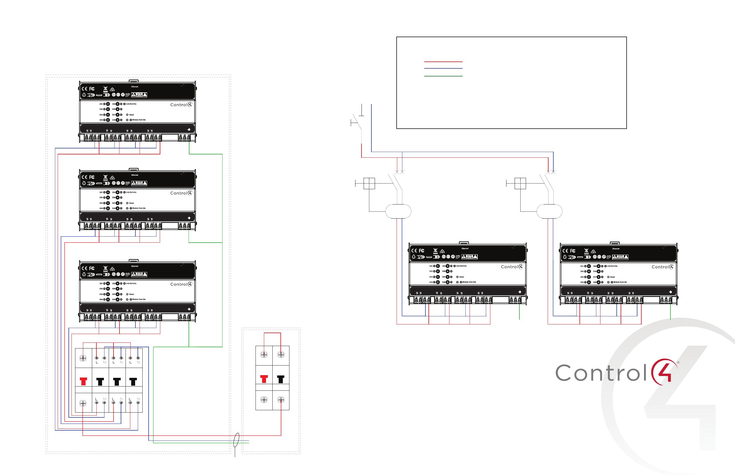
IEC Diagrams color code
Red Line
Blue Neutral
Green Earth ground
• The wire colors shown in the “IEC Diagrams color code” table are examples only.
Actual wire colors dier by country and/or voltage.
• Circuit breaker and RCBO sizes are indicative only, actual sizes could vary based on
local electrical requirements and regulations.
MAIN
SWITCH
220-240v Line Input
Neutral Line Input
16A
30mA
RCBO
Earth
Important!
Use at least 1 RCBO per unit.
A dedicated RCBO provides both
residual and over-current protection.
In countries using a single 300 mA to
500 mA RCBD, a dedicated RCCB or
MCB is recommended for each module.
16A
30mA
RCBO
Earth
C4-DIN-8RELSW-E
8-Channel Relay Switch
ATTENTION: Risque de choc électriqueNe pas ouvrir
This device complies with part 15 of the FCC rules and ISED’s license-exempt
RSSs. Operation is subject to the following two conditions: (1) this device
may not cause harmful interference, and (2) this device must accept any
interference received, including interference that may cause undesired
operation.
CAN ICES-3 (B)/NMB-3(B)
100-277V ,50/60 Hz
240V ,50 Hz
64A Max Total
16A Max per Circuit
16A Max per Channel
1 HP Max per Channel @ 120V
2 HP Max per Channel @240V
Refer to documentation
for load ratings
Patent Pending
Load 3
Load 4
Load 5
Load 6
Load 7
Load 8
Load 1
Load 2
Neutral 1
Line 1
Neutral 2
Line 2
Neutral 3
Line 3
Neutral 4
Line 4
Aux in
Aux out
Load 3
Load 4
Load 5
Load 6
Load 7
Load 8
Lighting Control Subboard
Main Electrical
Switchboard
Neutral & Earth bars
Sub-Main TPS Cable
C4-DIN-8RELSW-E
8-Channel Relay Switch
ATTENTION: Risque de choc électriqueNe pas ouvrir
This device complies with part 15 of the FCC rules and ISED’s license-exempt
RSSs. Operation is subject to the following two conditions: (1) this device
may not cause harmful interference, and (2) this device must accept any
interference received, including interference that may cause undesired
operation.
CAN ICES-3 (B)/NMB-3(B)
100-277V ,50/60 Hz
240V ,50 Hz
64A Max Total
16A Max per Circuit
16A Max per Channel
1 HP Max per Channel @ 120V
2 HP Max per Channel @240V
Refer to documentation
for load ratings
Patent Pending
Load 3
Load 4
Load 5
Load 6
Load 7
Load 8
Load 1
Load 2
Neutral 1
Line 1
Neutral 2
Line 2
Neutral 3
Line 3
Neutral 4
Line 4
Aux in
Aux out
Load 3
Load 4
Load 5
Load 6
Load 7
Load 8
Isolation
SW
RCBO
1Oa
30mA
30mA 30mA
RCBO
1Oa
RCBO
1Oa
Main
SW
MCB
16A
For IEC Installations
Copyright ©2020, Wirepath Home Systems, LLC. All rights reserved.
Control4 and Snap AV and their respective logos are registered trademarks
or trademarks of Wirepath Home Systems, LLC, dba “Control4” and/or dba
“SnapAV” in the United States and/or other countries. Control4, SnapAV,
and Wirepath are also registered trademarks or trademarks of Wirepath
Home Systems, LLC. Other names and brands may be claimed as the
property of their respective owners. All specifications subject to change
without notice.
200-00595-C
2020-01-14 MS
C

