Control4 C4-TV120277-BL Installation guide
- Type
- Installation guide

™
Warnings and considerations
WARNING! Turn OFF electrical power before installing or servicing this
product. Improper use or installation can cause SERIOUS INJURY, DEATH
or LOSS/DAMAGE OF PROPERTY.
ATTENTION! ATTENTION! Coupez l’alimentation électrique avant
d’installer ou de réparer ce produit. Une mauvaise installation ou utilisation
peut entraîner des blessures graves, décès ou perte / dommages à la
propriété.
WARNING! This device must be protected by a circuit breaker (20A max).
ATTENTION! Cet appareil doit être protégé par un disjoncteur (20A max.)
WARNING! Ground this device in accordance with the National Electric
Code (NEC) requirements. DO NOT rely solely upon the yoke plate’s
contact with a metal wallbox for adequate grounding. Use the device’s
ground wire to make a secure connection to the safety ground of the
electrical system.
ATTENTION! Cet appareil doit être en conformité avec le Code national
de l’électricité (NEC). Ne comptez pas uniquement au contact de la
plaque avant avec un boîtier mural métallique pour la mise à la terre
adéquate. Utilisez cet appareil à la terre de l’appareil pour établir une
connexion sécurisée au système électrique.
IMPORTANT! This device must be installed by a licensed electrician in
accordance with all national and local electrical codes.
IMPORTANT! If you are unsure about any part of these instructions,
consult a qualified electrician.
IMPORTANT! Use this device only with copper or copper-clad wire. Do
not use aluminum wiring. This product has not been approved for use with
aluminum wiring.
IMPORTANT! To reduce the risk of overheating and possible damage
to other equipment, do not install to control a receptacle or a motor-
operated appliance.
IMPORTANT! Using this product in a manner other than outlined in this
document voids your warranty. Further, Control4 is NOT liable for any
damage incurred with the misuse of this product. See “Troubleshooting.”
IMPORTANT! Do NOT use a power screwdriver to install this device. If you
do, you may overtighten the screws and strip them. Also, overtightening
the screws may interfere with proper button operation.
IMPORTANT! This is an electronic device with intricate components.
Handle and install with care!
IMPORTANT! When used in conjunction with an Auxiliary Keypad
(C4-KA-xx), the wire connecting the Auxiliary Keypad to the dimmer must
not exceed 150 feet (45 m) at 120VAC, and 100 feet (30 m) at 277VAC.
Installation instructions
1 Ensure that the location and intended use meet the following criteria:
• Do not exceed the load capacity requirements of the dimmer. Refer to the
load ratings in the specifications above for details.
• Install in accordance with all applicable national and local electrical codes.
• The range and performance of the wireless control system is highly
dependent on the following: (1) distance between devices; (2) layout
of the home; (3) walls separating devices; and (4) electrical equipment
located near devices.
2 Turn o the local electrical power by either switching o the circuit breaker or
removing the fuse from the fuse box. To ensure the wires do NOT have power
running to them, use an inductive voltage detector.
Supported Model
• C4-TV120277 0-10V Dimmer
Introduction
The Control4® 0-10V Dimmer operates independently or as part of a Control4
home automation system. It installs in a standard back box using typical wiring
standards and communicates to the Control4 system using a wireless connection.
Box contents
• 0-10V Dimmer
• Wire nuts
• Warranty card
• 0-10V Dimmer Installation Guide (this document)
Specifications and supported load types
The specifications are described below.
Model number C4-TV120277-xx
Power requirements 120-277VAC +/-10%, 50/60Hz
This device requires a neutral AC connection.
See “Sample Wiring Configurations” later in this
guide.
Power consumption 120V: 485 mW
277V: 1.18 W
Load types and ratings
Supported load types Four-wire 0-10V and 1-10V dimmable
fluorescent ballasts and LEDs, sink or source.
Maximum load (switched hot) 120V: 15A
277V: 8A
Maximum load (0-10V
Control)
100mA sink or source
Environmental
Operational temperature 32˚ F - 104˚ F (0˚ C - 40˚ C)
All load ratings are based on an ambient
temperature of 25˚ C
Humidity 5% to 95% non-condensing
Storage -4˚F ~ 158˚F (-20˚C ~ 70˚C)
Miscellaneous
Control communications ZigBee, IEEE 802.15.4, 2.4 GHz, 15-channel
spread spectrum radio
Wallbox volume 5.75 cubic inches
Weight 0.12 lb. (0.05 kg)
Shipping weight 0.18 lb. (0.08 kg)
0-10V Dimmer
Installation Guide
NOTE: The back box wiring shown in this document is an example. Your
wire colors and functions may dier. If you are not sure which wires are
the Line In/Hot, Neutral, Load, and Earth Ground wires, have a trained
electrician perform the installation.
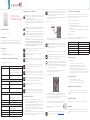
3 Prepare each wire. Wire insulation should be stripped back 5/8 of an inch
from the wire end (see Figure 1).
Figure 1. Strip wire insulation
4 Identify your wiring application, and then see the appropriate wiring diagram
in the “Sample Wiring Configurations” section below.
IMPORTANT! Not grounding this product as described in the section,
“Warnings and Considerations,” may result in an installation less immune
to damage caused by electrical disturbances, such as ESD or lightning,
and may void the warranty.
5 Identify and connect the dimmer wires to the back box wires using the wire
nuts.
IMPORTANT! The yellow wire is not a traditional traveler. It cannot directly
power a lighting load. It must be used only to connect to a Control4
Auxiliary Keypad. See “Sample Wiring Configurations.”
TIP: If you are using a Control4 push-on (screwless) faceplate in a multi-
gang installation, attach the black faceplate sub-plate to all of the devices
that will be installed into the wallbox prior to attaching the devices to the
wallbox. This will help ensure that all the devices are properly aligned and
on the same plane after installation.
6 Fit the wires back into the back box. Bend the wires in a zigzag pattern so
that they easily fold into the back box (Figure 2).
Figure 2. Bend the wires
7 Align the dimmer to the back box (the load rating label should be at the
bottom) and fasten it with screws. Tighten the screws until the back side of
the yoke plate is even with the wall surface, but no further. Overtightening can
warp the dimmer and cause mechanical malfunction.
8 Install the Control4 Faceplate following the instructions in the Faceplate
Installation Guide or attach a standard Decora-style faceplate.
9 Turn ON power at the circuit breaker or replace the fuse
from the fuse box.
NOTE: If the light flickers, adjust the dimmer’s max/min settings in
Composer (e.g. min 15%, max 85%). See ctrl4.co/dimmersettings.
Operation and configuration
On initial power up, all status LEDs on the dimmer will illuminate green indicating
that the device has power. To set up this dimmer for use with a Control4 system,
refer to the Composer Pro User Guide.
To operate this dimmer as a stand-alone device:
• Click the top button to turn the light on.
• Click the bottom button to turn the light o.
• Press and hold the top button to ramp the light up. Release the button at the
desired light level.
• Press and hold the bottom button to fade the light down. Release the button
at the desired light level.
Button tap sequences
The button tap sequences are defined in the table below. Button tap sequences
that require a single (1) button should use the top button.
Function Button sequence
Identify 4
ZigBee channel 7
Reboot 15
Factory reset 9-4-9
Leave mesh and reset 13-4-13
Troubleshooting
If the light does not turn on:
• Ensure at least one LED on the face of the dimmer is lit.
• Ensure the light bulb is not burned out and is screwed in tightly.
• Ensure that the circuit breaker is not turned OFF or tripped.
• Check for proper wiring (see “Sample Wiring Configurations”).
• For help on the installation or operation of this product, email or call the
Control4 Technical Support Center. Please provide your exact model number.
Contact support@control4.com or see the web site www.control4.com.
Care and cleaning
• Do NOT paint the dimmer or its wall plate.
• Do NOT use any chemical cleaners to clean the dimmer.
• Clean surface of the dimmer with a soft damp cloth as needed.
Regulatory/Safety information
To review Regulatory information for your particular Control4 products, see
the information located on the Control4 website at: http://www.control4.com/
regulatory/.
Patent information
Applicable patents are available at http://www.control4.com/legal/patents.
Warranty
For complete warranty information, including details on consumer legal rights as
well as warranty exclusions, review the Warranty card or visit www.control4.com/
warranty.

™
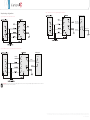
Sample wiring configurations
Figure 3. Single device location, with neutral connection
Figure 4. Multiple device location using Auxiliary Keypad, with neutral connection
IMPORTANT! When used in conjunction with an Auxiliary Keypad (C4-KA-xx), the wire connecting the Auxiliary Keypad to the dimmer must not exceed 150 feet
(45 m) at 120VAC, and 100 feet (30 m) at 277VAC.
Auxiliary
Line in/Hot
Black
Black
White
White
Red
Purple
Purple
Neutral in
Yellow
Blue/White
Auxiliary Keypad
Figure 5. Multiple device location using Configurable Keypad, neutral required
Line in/Hot
Black
White
Neutral in
Green/
Yellow
Earth ground
Configurable Keypad
Copyright ©2014 Control4. All rights reserved. Control4, the Control4 logo, the Control4 iQ logo and the Control4 certified logo are registered trademarks or trademarks of Control4 Corporation in
the United States and/or other countries. All other names and brands may be claimed as the property of their respective owners Pricing and specifications are subject to change without notice
200-00312-C 10162019 LW
-
 1
1
-
 2
2


Control4 C4-TV120277-BL Installation guide
- Type
- Installation guide
Ask a question and I''ll find the answer in the document
Finding information in a document is now easier with AI
in other languages
Related papers
-
Control4 Neeo Remote Quick start guide
-
-
-
-
-
Control 4 C4-KA-BL Installation guide
-
-
-
-