Page is loading ...

39" MULTI-PURPOSE CABINET
39" ARMOIRE POLYVALENTE
39" GABINETE MULTIUSO
BEFORE BEGINNING ASSEMBLY
– READ DIRECTIONS THOROUGHLY
– ASSEMBLE NEAR DESIRED LOCATION
– TWO-PERSON ASSEMBLY IS RECOMMENDED
AVANT DE COMMENCER L’ASSEMBLAGE
– LISEZ COMPLÈTEMENT LES INSTRUCTIONS
– ASSEMBLEZ À PROXIMITÉ DE L'EMPLACEMENT SOUHAITÉ
– IL EST RECOMMANDÉ DE SE METTRE À DEUX PERSONNES
POUR L'ASSEMBLAGE
ANTES DE COMENZAR AL ENSAMBLAJE
– LEE LAS INSTRUCCIONES MINUCIOSAMENTE
– ENSAMBLA CERCA DE LA UBICACIÓN FINAL
– SE RECOMIENDAN DOS PERSONAS PARA ENSAMBLAR
ASSEMBLY & INSTALLATION INSTRUCTIONS • INSTRUCTIONS POUR L’ASSEMBLAGE ET L’INSTALLATION • INSTRUCCIONES PARA LA INSTALACION
Model Number(s):
N
o
de modèle:
Numero(s) de:
TOOLS NEEDED FOR ASSEMBLY*
OUTILS REQUIS POUR L'ASSEMBLAGE*
HERRAMIENTAS NECESARIAS PARA LA
INSTALACIÓN*
*TOOLS NOT INCLUDED
*OUTILS NON COMPRIS
*HERRAMIENTAS NO INCLUIDAS
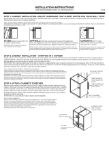
WIDE SIDE
CÔTÉ LARGE
LADO ANCHO
WHEN ASSEMBLED, WIDE SIDE SHOULD BE ON THE LEFT.
ASSEMBLE DE COTE DE LARGE DEVRAIT ETRE SUR LA GAUCHE.
EL LADO ANCHO REUNIDO DEBE ESTAR EN LA IZQUIERDA.
NARROW SIDE
CÔTÉ ÉTROIT
LADO ANGOSTO
STUD FINDER
DÉTECTEUR DE
MONTANTS
DETECTOR DE VIGAS
U180136 / 0614
ESM3970SW

HELPFUL TIPS
SUGGESTIONS UTILES
SUGERENCIAS ÚTILES
DO NOT RETURN PRODUCT TO THE STORE!
If you have any problems or missing parts,
please contact our parts department at the
number provided.
NE PAS RETOURNER LE PRODUIT AU
MAGASIN! En cas de problèma ou de pièces
manquantes, joindre le service des pièces au
numéro fourni.
¡EN LOS ESTADOS UNIDOS, NO DEVUELVA
EL PRODUCTO A LA TIENDA! Si tuviera
algún problema o pieza faltante, por favor,
comuníquese con nuestro departamento de
piezas llamando al número mencionado.
TWO PERSON ASSEMBLY. We recommend assembling this cabinet with two people to
avoid damaged or broken product.
ASSEMBLAGE PAR DEUX PERSONNES. Nous recommandons de se mettre à deux
personnes pour assembler de cette armoire pour éviter d'endommager ou de casser le produit.
SE NECESITAN DOS PERSONAS PARA ENSAMBLARLO. Recomendamos
dos personas para ensamblar este gabinete para así evitar roturas o daños al producto.
INSTALLING CAM LOCKS
Align the arrow toward the outside edge of the panel.
Ensure that the cam lock is seated ush with the
surface of the panel.
INSTALLER LES VERROUILLAGES À CAME
Alignez la èche vers le bord extérieur du panneau. Assurez-
vous que le verrouillage à came est posé à ras de la surface
du panneau.
COMO INSTALAR LOS CIERRES DE LEVA
Alinea la echa hacia el borde exterior del panel. Asegúrate
de que el cierre de leva esté ubicado a ras con al supercie
del panel.
TIGHTENING CAM LOCKS
Once panels are joined, turn the cam lock until it
stops. Cam is considered “locked” when it stops
between the 2 and 4 o’clock positions (when starting
from the 9 o'clock position).
SERRER LES VERROUILLAGES À CAME. Une fois que les panneaux sont joints, tournez le verrouillage à came jusqu'à ce qu'il s'arrête.
La came est considérée comme «verrouillée» lorsqu'elle s'arrête entre les positions 2heures et 4heures (en étant partie de la position 9heures).
COMO APRETAR LOS CIERRES DE LEVA. Una vez los paneles estén unidos, gira el cierre de leva hasta que se detenga. La leva se
considera “cerrada” cuando se detiene entre las posiciones de las 2 y 4 horas del reloj (al iniciar en la posición de las 9 horas).
TO CALL FROM THE UNITED STATES:
888-774-8062
6AM-4PM PST MONDAY-FRIDAY
PARA LLAMAR DE MEXICO: 001-714-578-2525
6AM-4PM PST LUNES-VIERNES
MIN
LOCKED
MAX

HARDWARE
QUINCAILLERIE
HERRAJES
CAM LOCK
(QTY. 18)
VERROUILLAGE À CAME
CIERRE DE LEVA
CAM BOLT
(QTY. 18)
BOULON À CAME
PERNO DE LEVA
DOWEL
(QTY. 16)
GOUJON
CLAVIJA
#6 x ½" SCREW
(QTY. 18)
VIS
TORNILLO
HINGE PLATE
(QTY. 6)
PLAQUE DE CHARNIÈRE
PLACA DE BISAGRA
HINGE
(QTY. 6)
CHARNIÈRE
BISAGRA
#6 X 1⁵₈" SCREW
(QTY. 4)
VIS
TORNILLO
#8-32 x ¾" SCREW
(QTY. 4)
VIS
TORNILLO
BUMPER
(QTY. 4)
BUTÉE
PROTECTOR
HANDLE
(QTY. 2)
POIGNÉE
ASA
SHELF CLIP
(QTY. 24)
TAQUET POUR ÉTAGÈRE
GANCHO PARA ESTANTE
“L” BRACKET
(QTY. 1)
SUPPORT EN «L»
SOPORTE EN L
HANG ROD CUP
(QTY. 4)
COUPELLE DE SUPPORT DE TRINGLE
SOPORTE DE LA BARRA PARA COLGAR
HANG ROD
(QTY. 2)
TRINGLE
BARRA PARA COLGAR
NAIL
(QTY. 40)
CLOU
CLAVO
NAIL GUIDE
(QTY. 1)
SERRURE DE CAME
BLOQUEO DE LA LEVA
t
a b
h
c d
r s w
m n pk
ge f

EXPLODED VIEW
VUE ÉCLATÉE
VISTA AMPLIADA
A
B
E
C
C
J
L
J
L
J
L
F
M
P
G
H
PANEL A
Panels are identied on edges.
Les panneaux sont identiés
sur les bords.
Los paneles están marcados
en los bordes.

LEFT SIDE PANEL
(QTY. 1)
PANNEAU LATÉRAL GAUCHE • PANEL DEL LADO IZQUIERDO
RIGHT SIDE PANEL
(QTY. 1)
PANNEAU LATÉRAL DROIT • PANEL DEL LADO DERECHO
TOP / BOTTOM PANEL
(QTY. 2)
PANNEAUINFÉRIEUR / ÉTAGÈRE FIXE • PANEL INFERIOR / ESTANTE FIJO
PARTITION
(QTY. 1)
PARTITION • DIVISIÓN
TOP RAIL
(QTY. 1)
TRAVERSE SUPÉRIEURE
RIEL SUPERIOR
TOEKICK
(QTY. 1)
COUP-DE-PIED
ZÓCALO
LARGE BACK RAIL
(QTY. 1)
GRAND RAIL ARRIÈRE
RIEL POSTERIOR GRANDE
SMALL BACK RAIL
(QTY. 1)
PETIT RAIL ARRIÈRE
RIEL POSTERIOR PEQUEÑO
BACK PANEL
(QTY. 1)
PANNEAU ARRIÈRE
PANEL POSTERIOR
SHELF
(QTY. 3)
ÉTAGÈRE • ESTANTE
DOORS
(QTY. 2)
PORTE
PUERTA
SHELF
(QTY. 3)
ÉTAGÈRE • ESTANTE
PANELS
PANNEAUX
PANELES
A B
C
H J
L
K
M P
F G
E
PANEL A
Panels are identied on edges.
Les panneaux sont identiés sur les bords.
Los paneles están marcados en los bordes.

ATTACH HARDWARE TO PANELS A & B
Attacher la quincaillerie aux panneaux A et B
Sujeta los herrajes a los paneles A y B
HINGE PLATE
(QTY. 6)
PLAQUE DE CHARNIÈRE
PLACA DE BISAGRA
HANG ROD CUP
(QTY. 2)
COUPELLE DE SUPPORT DE TRINGLE
SOPORTE DE LA BARRA PARA COLGAR
#6 x ½" SCREW
(QTY. 2)
VIS
TORNILLO
1
e r d
A
B
Notes/Remarques/Notas:
• Do not fully tighten hinge plate, to allow for easier installation of the doors.
• Ne serrez pas entièrement le plat de charnière, pour tenir compte d’une installation plus facile des portes.
• No apriete completamente la placa de la bisagra, para tener en cuenta una instalación más fácil de las puertas.
r d

ATTACH HARDWARE TO PANELS A & B
Attacher la quincaillerie aux panneaux A et B
Sujeta los herrajes a los paneles A y B
CAM BOLT
(QTY. 16)
BOULON À CAME
PERNO DE LEVA
2
b
A
B

3
ATTACH HARDWARE TO PANEL E
Attacher la quincaillerie aux panneaux E
Sujeta los herrajes a los paneles E
CAM BOLT
(QTY. 1)
BOULON À CAME
PERNO DE LEVA
DOWEL
(QTY. 4)
GOUJON
CLAVIJA
HANG ROD CUP
(QTY. 1)
COUPELLE DE SUPPORT DE TRINGLE
SOPORTE DE LA BARRA PARA COLGAR
#6 x ½" SCREW
(QTY. 1)
VIS
TORNILLO
b
E
c r d

4
ATTACH HARDWARE TO PANELS C
Attacher la quincaillerie aux panneaux C
Sujeta los herrajes a los paneles C
CAM LOCK
(QTY. 8)
VERROUILLAGE À CAME
CIERRE DE LEVA
DOWEL
(QTY. 8)
GOUJON
CLAVIJA
a
C
C
c

ATTACH PANEL C TO PANEL A
Attacher le panneau C au panneau A
Une el panel C al panel A
5
Notes/Remarques/Notas:
• Raw unnished edges should be facing up. Finished edges should be facing down.
• Les bords bruts non nis doivent regarder vers le haut. Les bords nis doivent regarder vers le bas.
• Las bordes sin terminar deben mirar hacia arriba. Las bordes terminados deben mirar hacia abajo.
A
C
MIN
LOCKED
MAX
WIDE SIDE
CÔTÉ LARGE
LADO ANCHO
NARROW SIDE
CÔTÉ ÉTROIT
LADO ANGOSTO

6
CAM LOCK
(QTY. 3)
VERROUILLAGE À CAME
CIERRE DE LEVA
ATTACH PANEL M TO PANEL A
Attacher le panneau M au panneau A
Une el panel M al panel A
A
M
a
MIN
LOCKED
MAX

ATTACH PANEL E TO PANEL C & M
Attacher le panneau E au panneau C et M
Une el panel E a los paneles C y M
7
Notes/Remarques/Notas:
• Raw unnished edges should be facing up. Finished edges should be facing down.
• Les bords bruts non nis doivent regarder vers le haut. Les bords nis doivent regarder vers le bas.
• Las bordes sin terminar deben mirar hacia arriba. Las bordes terminados deben mirar hacia abajo.
C
A
E
M
MIN
LOCKED
MAX
CAM BOLT
(QTY. 1)
BOULON À CAME
PERNO DE LEVA
HANG ROD CUP
(QTY. 1)
COUPELLE DE SUPPORT DE TRINGLE
SOPORTE DE LA BARRA PARA COLGAR
#6 x ½" SCREW
(QTY. 1)
VIS
TORNILLO
b r d

8
ATTACH PANEL C TO PANEL A
Attacher le panneau C au panneau A
Une el panel C al panel A
Notes/Remarques/Notas:
• Raw unnished edges should be facing up. Finished edges should be facing down.
• Les bords bruts non nis doivent regarder vers le haut. Les bords nis doivent regarder vers le bas.
• Las bordes sin terminar deben mirar hacia arriba. Las bordes terminados deben mirar hacia abajo.
MIN
LOCKED
MAX
C
A
E
WIDE SIDE
CÔTÉ LARGE
LADO ANCHO
NARROW SIDE
CÔTÉ ÉTROIT
LADO ANGOSTO

ATTACH PANEL F
Attacher le panneau F
Une el panel F
CAM LOCK
(QTY. 2)
VERROUILLAGE À CAME
CIERRE DE LEVA
DOWEL
(QTY. 2)
GOUJON
CLAVIJA
a c
9
MIN
LOCKED
MAX
F
A

10
ATTACH PANEL G
Attacher le panneau G
Une el panel G
CAM LOCK
(QTY. 2)
VERROUILLAGE À CAME
CIERRE DE LEVA
DOWEL
(QTY. 2)
GOUJON
CLAVIJA
a c
MIN
LOCKED
MAX
G

ATTACH PANEL P
Attacher le panneau P
Une el panel P
11
E
P
MIN
LOCKED
MAX
CAM LOCK
(QTY. 3)
VERROUILLAGE À CAME
CIERRE DE LEVA
a

12
ATTACH PANEL B
Attacher le panneau B
Une el panel B
B
Notes/Remarques/Notas:
• Raw unnished edges should be facing up. Finished edges should be facing down.
• Les bords bruts non nis doivent regarder vers le haut. Les bords nis doivent regarder vers le bas.
• Las bordes sin terminar deben mirar hacia arriba. Las bordes terminados deben mirar hacia abajo.
MIN
LOCKED
MAX

13
MARK FIXED PANEL LOCATION ON TOP & BOTTOM PANEL
Marquez l’emplacement du panneau xe sur le panneau supérieur et inférieur
Marca la ubicación del panel jo en los paneles superior e inferior
#6 X 1⁵₈" SCREW
(QTY. 4)
VIS
TORNILLO
“L” BRACKET
(QTY. 1)
SUPPORT EN «L»
SOPORTE EN L
#6 x ½" SCREW
(QTY. 2)
VIS
TORNILLO
g
d
p
Notes/Remarques/Notas:
• Mark the location of the xed partition on the top panels.
• Marquez l'emplacement de la partition xe sur les panneaux supérieurs.
• Marque la ubicación de la división ja en los paneles superiores.
x4

14
SECURE BACK PANEL H
Fixez le panneau arrière H
Asegura el panel posterior H
Notes/Remarques/Notas:
• Ensure cabinet is square
and secure top two corners
rst. Mark the position of
the partition across the
back panel.
• Assurez que le module est les
coins carrés et sécurisés du
principal deux d'abord. Marquez la
position de la partition à travers le
panneau arrière.
• Asegúrese que la cabina sea esquinas
cuadradas y seguras de la tapa dos
primero. Marque la posición de la
división a través del panel trasero.
1 3
4
2
NAIL
(QTY. 2)
CLOU
CLAVO
NAIL GUIDE
(QTY. 1)
SERRURE DE CAME
BLOQUEO DE LA LEVA
w t
The back panel should set between the lip
on both side panels.
Le panneau arrière devrait placer entre la lèvre
sur les deux panneaux latéraux.
El panel trasero debe jar entre el labio
en los ambos paneles laterales.

15
SECURE BACK PANEL H
Fixez le panneau arrière H
Asegura el panel posterior H
Notes/Remarques/Notas:
• Secure perimeter of back
panel spacing nails
approximately 8"-10" apart.
• Fixez solidement le pourtour du
panneau arrière en espaçant les
clous d'environ 20,32cm à
25,40cm (8 à 10po).
• Asegura el perímetro del panel
posterior dejando aproximadamente
de 8" a 10" (20,32 a 25,4 cm)
entre cada clavo de separación.
1 3
4
2
NAIL
(QTY. 38)
CLOU
CLAVO
NAIL GUIDE
(QTY. 1)
SERRURE DE CAME
BLOQUEO DE LA LEVA
g t
Notes/Remarques/Notas:
• Secure perimeter of back
panel spacing nails
approximately 8"-10" apart.
• Fixez solidement le pourtour du
panneau arrière en espaçant les
clous d'environ 20,32cm à
25,40cm (8 à 10po).
• Asegura el perímetro del panel
posterior dejando aproximadamente
de 8" a 10" (20,32 a 25,4 cm)
entre cada clavo de separación.
/