tekmar Universal Reset Module 422 Installation guide

Type
Installation guide

This manual is also suitable for

D 422
08/07
- Data Brochure
Universal Reset Module 422
1 of 32 © 2007 D 422 - 08/07
tN4 Compatible
Two Outdoor Reset Temperatures
Single On-Off or Modulating Boiler
Powered Pump Outputs
DHW Operation
Variable Speed Injection Pump
Floating Action Valve
Includes Sensors
Features:
Information
Brochure
Choose controls
to match
application
1
Application
Brochure
Design your
mechanical
applications
2
Wiring
Brochure
Wiring and
installation of
specific control
4
Job
Record
Record settings &
wiring details for
future reference
6
Data
Brochure
Control settings
and sequence of
operation
5
Rough-in
Wiring
Rough-in
wiring
instructions
3
The Universal Reset Module 422 provides outdoor reset to a hydronic heating system in order to maximize comfort and
efficiency. The 422 can operate a single on / off boiler or a single modulating boiler. The 422 can override the outdoor reset
water temperature to provide Domestic Hot Water or Setpoint operations. The 422 can operate two outdoor reset water
temperatures, either one boiler water temperature and a single mix water temperature, or two mix water temperatures. To
operate two mixing devices, a Mixing Expansion Module must be connected to the 422. The single mix output can operate
a floating action mixing valve or a variable speed injection pump.
Introduction
51
52 53 54 55 56 57 58 59 60 61 62 63 64 65
Boiler DHW Setpoint C C2 tN4 C Com Boil Mix Com Out+Opn Cls
Demand Demand 24 V (ac) Boil/Mix2 R R Mod (dc)
R
66 67 68 69 70
Primary Mix Sys P1
10 A
max.
75 76 77 78
NN
DHW Variable Speed
71 72 73 74
Pump Pump
N
Pump NPump
tN4
H7008B
tN4 Boiler / Mix 2
Boil Sens Sup / Ret
Boiler On-Off / Mod
Off / tekmar Stager
Off / Flushing
Powered OutputOutput 1 VA
Floating Output:
24 V (ac) 8 VA
Made in Canada
Meets Class B: Canadian
ICES & FCC Part 15
Test
Var. Pump Fuse
T2.5 A 250 V
Universal Reset Module 422
Item
Menu
tektra 991-03
Var. Pump: 115 V (ac) 2.5 A
Demands: 20 - 260 V (ac)
Relay Rating: 115 V (ac) 5 A
/
Do not apply power
2.5 A
© 2007 D 422 - 08/07 2 of 32
Table of Contents
Table of Contents ...........................................................2
Display and DIP Switches ..............................................2
Dip Switch Settings ................................................2
Access Level ...........................................................3
Display and Symbols Description............................4
User Interface ........................................................5
Display Menus ................................................................6
View Menu ..............................................................6
Adjust Menu ............................................................8
Miscellaneous Menu .............................................13
Testing the Control ....................................................... 14
Sequence of Operation ................................................. 16
tekmarNet
®
4 Communication ...............................16
Outdoor Reset ......................................................16
Boiler Temperature Control ..................................19
tekmar Stager Operation ......................................21
Boil Enable ............................................................22
Direct Fired - DHW Tank as a Heat Source .........22
Zone Load Shedding ............................................22
Mixing Operation ..................................................22
Domestic Hot Water Temperature Operation .......23
DHW with Low Temperature Boilers .....................25
Setpoint Temperature Operation ...........................25
Pump Operation ....................................................27
Pump Exercising ...................................................27
Error Messages ............................................................28
Troubleshooting ............................................................31
Warranty .......................................................................32
Set the DIP switch settings prior to making adjustments
to the control through the user interface. Setting the DIP
switches determines which menu items are displayed in
the user interface.
If you change a DIP switch setting while the control is
powered up, the LCD display returns to the View menu.
Lock / Unlock
Use the Lock / Unlock DIP switch to lock and unlock the Access
Level of the 422 and all connected tN4 devices, including
tN4 thermostats. For details, see “Access Levels”
Once locked, the access level in all devices cannot be
viewed or changed.
To determine if the control is currently locked a small
segment representing a padlock is viewed in the bottom
right hand corner of the display.
To unlock the Access Level, set the DIP switch to
Unlock.
To lock the Access Level, set the DIP switch to Lock.
Dip Switch Settings
Display and DIP Switches
51
52 53 54 55 56 57 58 59 60 61 62 63 64 65
Boiler DHW Setpoint C C2 tN4 C Com Boil Mix Com Out+Opn Cls
Demand Demand 24 V (ac) Boil/Mix2 R R Mod (dc)
R
66 67 68 69 70
Primary Mix Sys P1
10 A
max.
75 76 77 78
NN
DHW Variable Speed
71 72 73 74
Pump Pump
N
Pump NPump
tN4
H7008B
tN4 Boiler / Mix 2
Boil Sens Sup / Ret
Boiler On-Off / Mod
Off / tekmar Stager
Off / Flushing
Powered OutputOutput 1 VA
Floating Output:
24 V (ac) 8 VA
Made in Canada
Meets Class B: Canadian
ICES & FCC Part 15
Test
Var. Pump Fuse
T2.5 A 250 V
Universal Reset Module 422
Item
Menu
tektra 991-03
Var. Pump: 115 V (ac) 2.5 A
Demands: 20 - 260 V (ac)
Relay Rating: 115 V (ac) 5 A
/
Do not apply power
2.5 A
tN4 Boiler / Mix 2
Boil Sens Sup / Ret
Boiler On-Off / Mod
Off / tekmar Stager
Off / Flushing
/
3 of 32 © 2007 D 422 - 08/07
Access Level
tN4 Boiler / Mix 2
Use the tN4 Boiler / Mix 2 DIP switch to select whether
the second tN4 bus (terminals 59-60) is to operate as
a boiler water temperature or as a second mixing water
temperature.
If set to Boiler, this creates a system with one boiler and
one mix water temperature.
If set to Mix 2, this creates a system with two mix water
temperatures. If Mix 2 is selected, a mixing expansion
module must be connected to the Boiler / Mix 2 bus.
Boiler Sup / Ret
Use the Boiler Sensor Supply / Return DIP switch to select
the location of the boiler sensor.
If the boiler sensor is located on the supply, this DIP
switch should be set to Sup. The 422 is the control that
determines the boiler water temperature. Set the boiler’s
aquastat at least 20°F (11.0°C) higher than the Boiler
Maximum setting.
If the 422 provides a heat demand to an external boiler
control, this DIP switch must be set to Ret. Install the
boiler sensor on the return side of the boiler loop.
The boiler’s operating temperature is controlled by its
aquastat, or an external boiler reset control.
Boil On-Off / Mod
The Boil On-Off / Mod DIP switch selects whether the
control operates an On-Off boiler or the firing rate of a
Modulating boiler.
If set to Boil On-Off, the control operates an On-Off
boiler.
If set to Mod, the control operates a Modulating boiler.
Off / Flushing
The Off / Flushing DIP switch selects whether the control
operates a Flushing feature. Heating systems that use
potable water require periodic flushing to prevent the water
from stagnating.
The flushing operation occurs if any zone has not operated
for 7 days. All zones, mixing device(s), and applicable
system pumps are turned on for 4 minutes.
To activate the Flushing feature, set to Flushing.
To deactivate the Flushing feature, set to Off.
tekmar Stager / Off
Use the tekmar Stager / Off DIP switch when a tekmar
staging control is be connected to the 422 in order to
operate multiple boilers. A tekmar stager may include Boiler
Controls 264, 265, and 268.
If a tekmar Stager is installed, set to tekmar Stager. The
422 will then provide the stager with a target temperature
via a 0-10 V (dc) signal. When the tekmar Stager / Off
DIP switch is set to tekmar Stager, the Boiler Sensor
DIP switch must be set to Sup.
If a tekmar Stager is not installed, set to Off.
The Access Level restricts the number of Menus, Items,
and Adjustments that can be accessed by the user. The
Access Level setting is found in the Miscellaneous (MISC)
menu. Select the appropriate access level for the people
who work with the control on a regular basis.
There are two Access Level settings:
Installer (InS): This is the factory default setting. This
access level is sufficient for the normal set up of the
control.
Advanced (Ad): All of the control settings are available
to the user.
In the following menu tables, the access level the item is
visible in is shown in the access column.
© 2007 D 422 - 08/07 4 of 32
PUMP
Displays when the primary or mixing pump
is in operation.
BURNER
Displays when the burner contact is
closed.
LOCK
Displays when the access levels are
locked.
WARNING
Displays when an error exists.
COMMUNICATION BUS
Displays when tN4 thermostats are
connected.
DHW PUMP
Displays when the DHW Pump is in
operation.
°F, °C, %, HOURS, MINUTES
Units of measurement.
BOILER DEMAND
Displays when a boiler demand is present.
MIX 1 DEMAND
Displays when a mix 1 demand is present.
MIX 2 DEMAND
Displays when a mix 2 demand is present.
DHW DEMAND
Displays when a DHW demand is present.
SETPOINT DEMAND
Displays when a Setpoint demand is
present.
DEVICE OUTPUT SCALE
Displays output of the modulating boiler,
injection pump, or mixing valve.
OPEN / CLOSE
Displays whether the actuator is opening or
closing the mixing valve.
Item Field
Displays an
abbreviated name
of the selected item
Number Field
Displays the
current value of
the selected item
Status Field
Displays the current
status of the control’s
inputs, outputs and
operation. Most symbols
in the status field are
only visible when the
VIEW Menu is selected
Menu Field
Displays the
current menu
Symbols Description S
Display
Symbols Description
5 of 32 © 2007 D 422 - 08/07
User Interface
Use the User Interface available on the Liquid Crystal Display
(LCD) to setup and monitor the operation of the system.
Use the four push buttons to the left of the LCD (Menu,
Item, Up, Down) to select settings. As you enter settings,
record the settings in the Job Record J 422.
Menu
The menus display in the Menu Field at the top left side
of the LCD. Three menus are available: View, Adjust, and
Miscellaneous.
To select a menu, press and release the Menu button.
Item
In each menu, a group of items can be selected. The
abbreviated name of the selected item displays in the Item
field of the LCD display.
To view the next available item, press and release the
Item button.
To view the previous item, hold down the Item button.
and press and release the Up button.
Adjusting a Setting
To adjust a setting:
1. Select the appropriate menu using the Menu button.
2. Select the item using the Item button.
3. Use the Up or Down button to make the adjustment.
Default Item
To set the default item in the View menu, display the
item for more than five seconds.
After navigating menus, the display reverts back to the
default item after 60 seconds of button inactivity.
Continue
to next Item
Back to View Menu
Continue
to next Item
Continue
to next Item
© 2007 D 422 - 08/07 6 of 32
View Menu (1 of 2)
Item Field Range Access Description
-76 to 149°F
(-60.0 to 65.0°C)
InS
Ad
OUTDOOR SECTION B
Current outdoor air temperature as measured by the
outdoor sensor.
-22 to 266°F
(-30.0 to 130.0°C)
InS
Ad
MIX 1 SUPPLY SECTION B
Current Mix 1 supply water temperature as measured
by the Mix 1 supply sensor.
– – –, 35 to 230°F
(– – –, 1.5 to 110.0°C)
Ad
MIX 1 TARGET SECTION C
The Mix 1 target is the temperature the control
is currently trying to maintain at the Mix 1 supply
sensor. “– – –” is displayed when no heat is required
for Mix 1 zones.
-22 to 266°F
(-30.0 to 130.0°C)
InS
Ad
MIX 2 SUPPLY SECTION B
Current Mix 2 supply water temperature as measured
by the Mix 2 supply sensor.
Note: This item is only available when the tN4 DIP
switch is set to Mix 2.
– – –, 35 to 230°F
(– – –, 1.5 to 110.0°C)
Ad
MIX 2 TARGET SECTION C
The mix 2 target is the temperature the control
is currently trying to maintain at the Mix 2 supply
sensor. “– – –” is displayed when no heat is required
for mix 2 zones.
Note: This item is only available when the tN4 DIP
switch is set to Mix 2.
-22 to 266°F
(-30.0 to 130.0°C)
InS
Ad
BOILER SUPPLY SECTION C
Current boiler supply water temperature as measured
by the boiler sensor.
Note: This item is only available when the Boiler
Sensor Sup / Ret DIP switch is set to Sup.
The View menu items display the current operating
temperatures and status information of the system.
Continued on next page.
VIEW MENU
Display Menus
7 of 32 © 2007 D 422 - 08/07
Item Field Range Access Description
– – –, 35 to 230°F
(– – –, 1.5 to 110.0°C)
Ad
BOILER TARGET
SECTION C
The boiler target is the temperature the control is currently
trying to maintain at the boiler supply sensor. “– – –” is
displayed when no heat is required for boiler zones.
Note: This item is only available when the Boiler
Sensor Sup / Ret DIP switch is set to Sup.
-22 to 266°F
(-30.0 to 130.0°C)
InS
Ad
BOILER RETURN SECTION G
Current boiler return water temperature as measured
by the boiler sensor.
Note: This item is only available when the Boiler
Sensor Sup / Ret DIP switch is set to Ret.
0-100% Ad
BOILER MODULATION SECTION C
Current percent modulation of the boiler’s burner.
Note: This item is only available when the Boiler
On-Off / Mod DIP switch is set to Mod, and the Boiler
Sensor Sup / Ret DIP switch is set to Sup.
0 to 9999 hr
InS
Ad
BOILER
The total running time of the boiler since this item
was last cleared. To clear this item, press the Up
and Down buttons simultaneously while viewing
this item.
Note: This item is only available when the Boiler
Sensor Sup / Ret DIP switch is set to Sup.
View Menu (2 of 2)
After the last item, the control returns to the first item in the menu.
VIEW MENU
© 2007 D 422 - 08/07 8 of 32
Item Field
Range
Access Description
-60 to 45°F
(-51.0 to 7.0°C)
Default = 10°F
(-12.0°C)
InS
Ad
OUTDOOR DESIGN
SECTION B
The design outdoor air temperature used in the heat
loss calculations for the heating system. Typically set
to the temperature of the coldest day of the year.
VAr, FLt
Default = VAr
InS
Ad
MIX 1 MODE SECTION G
Select the type of mixing device to be used for Mix 1.
Options are variable speed injection pump (VAr) or
floating action (FLt).
1 HRF1
2 HRF2
3 Fancoil
4 Fin-tube Convector
5 Radiator
6 Baseboard
Default = 1
InS
Ad
MIX 1 TERMINAL SECTION B
The type of heating terminal units that are being
used in Mix 1 zones.
40 to 100°F
(4.5 to 38.0°C)
Default = 70°F (21.0°C)
Ad
MIX 1 INDOOR SECTION B
The design indoor air temperature used in the heat
loss calculation for Mix 1 zones. Typically set to
70°F (21.0°C).
70 to 220°F
(21.0 to 104.5°C)
Default = 120°F
(49.0°C)
InS
Ad
MIX 1 DESIGN SECTION B
The supply water temperature required for the Mix 1
zones on the typical coldest day of the year.
OFF, 40 to 150°F
(OFF, 4.5 to 65.5°C)
Default = OFF
Ad
MIX 1 MINIMUM SECTION G
The minimum allowed Mix 1 target temperature.
80 to 220°F, OFF
(26.5 to 104.5°C, OFF)
Default = 140°F
(60.0°C)
Ad
MIX 1 MAXIMUM SECTION G
The maximum allowed Mix 1 target temperature.
Adjust Menu (1 of 5)
The Adjust Menu items are the programmable settings
used to operate the mechanical equipment.
Continued on next page.
ADJUST MENU
9 of 32 © 2007 D 422 - 08/07
Item Field
Range
Access Description
30 to 230 seconds
Default = 105
Ad
MIX 1 MOTOR SECTION G
The time that the Mix 1 actuating motor requires to
operate from fully closed to fully open.
Note: This item is only available when the Mix 1
Mode setting is set to floating action (FLt).
1 HRF1
2 HRF2
3 Fancoil
4 Fin-tube Convector
5 Radiator
6 Baseboard
Default = 1
InS
Ad
MIX 2 TERMINAL SECTION B
The type of heating terminal units that are being
used in mix 2 zones.
Note: This item is only available when the tN4 DIP
switch is set to Mix 2.
40 to 100°F
(4.5 to 38.0°C)
Default = 70°F (21.0°C)
Ad
MIX 2 INDOOR SECTION B
The design indoor air temperature used in the heat
loss calculation for mix 2 zones. Typically set to
70°F (21.0°C).
Note: This item is only available when the tN4 DIP
switch is set to Mix 2.
70 to 220°F
(21.0 to 104.5°C)
Default = 120°F
(49.0°C)
InS
Ad
MIX 2 DESIGN SECTION B
The supply water temperature required for the mix 2
zones on the typical coldest day of the year.
Note: This item is only available when the tN4 DIP
switch is set to Mix 2.
OFF, 40 to 150°F
(OFF, 4.5 to 65.5°C)
Default = OFF
Ad
MIX 2 MINIMUM SECTION G
The minimum allowed mix 2 target temperature.
Note: This item is only available when the tN4 DIP
switch is set to Mix 2.
80 to 220°F
(26.5 to 104.5°C)
Default = 140°F
(60.0°C)
Ad
MIX 2 MAXIMUM SECTION G
The maximum allowed mix 2 target temperature.
Note: This item is only available when the tN4 DIP
switch is set to Mix 2.
30 to 230 seconds
Default = 105
Ad
MIX 2 MOTOR SECTION G
The time that the mix 2 actuating motor requires to
operate from fully closed to fully open.
Note: This item is only available when the tN4 DIP
switch is set to Mix 2. Availability also depends on
the type of mixing module being used.
1 HRF1
2 HRF2
3 Fancoil
4 Fin-tube Convector
5 Radiator
6 Baseboard
Default = 4
InS
Ad
BOILER TERMINAL SECTION B
The type of heating terminal units that are being
used in boiler zones.
Note: This item is only available when the Boiler
Sensor Sup / Ret DIP switch is set to Sup and the
tN4 DIP switch is set to Boiler.
Adjust Menu (2 of 5)
Continued on next page.
ADJUST MENU
© 2007 D 422 - 08/07 10 of 32
Item Field
Range
Access Description
40 to 100°F
(4.5 to 38.0°C)
Default = 70°F
(21.0°C)
Ad
BOILER INDOOR
SECTION B
The design indoor air temperature used in the heat
loss calculation for the boiler zones. Typically set to
70°F (21.0°C).
Note: This item is only available when the Boiler
Sensor Sup / Ret DIP switch is set to Sup and the
tN4 DIP switch is set to Boiler.
70 to 220°F
(21.0 to 104.5°C)
Default = 180°F
(82.0°C)
InS
Ad
BOILER DESIGN SECTION B
The supply water temperature required for boiler
zones on the typical coldest day of the year.
Note: This item is only available when the Boiler
Sensor Sup / Ret DIP switch is set to Sup and the
tN4 DIP switch is set to Boiler.
OFF, 80 to 180°F
(OFF, 26.5 to 82.0°C)
Default = 140°F
(60.0°C)
InS
Ad
BOILER MINIMUM SECTION C
The minimum allowed boiler target temperature and
boiler return protection temperature. Check the boiler
manufacturer’s manual for recommend supply water
temperatures.
120 to 225°F, OFF
(49.0 to 107.0°C, OFF)
Default = 200°F
(93.5°C)
Ad
BOILER MAXIMUM SECTION C
The maximum allowed boiler target temperature.
Note: This item is only available when the Boiler
Sensor Sup / Ret DIP switch is set to Sup and the
tekmar stager DIP switch is set to OFF.
0:00 to 3:00 min
Default = 0:10 min
Ad
FIRE DELAY SECTION C
The time delay the control can expect between the
time that the relay contact closes to fire the boiler
and when the burner actually fires.
Note: This item is only available when the Boiler
Sensor Sup / Ret DIP switch is set to Sup and the
tekmar stager DIP switch is set to OFF.
Au, 2 to 42°F
(Au, 1 to 23.5°C)
Default = Au
Ad
BOILER DIFFERENTIAL SECTION C
The temperature differential that the control is to use
when it is operating the boiler.
Note: This item is only available when the Boiler
Sensor Sup / Ret DIP switch is set to Sup and the
tekmar stager DIP switch is set to OFF.
10 to 230 seconds
Default = 30 seconds
Ad
BOILER MOTOR SECTION C
The amount of time required for the modulating
actuating motor to fully open the gas valve or operate
the fan speed from a stopped position to full speed
on a modulating boiler.
Note: This item is only available when the Boiler
Sensor Sup / Ret DIP switch is set to Sup, the Boiler
On-Off / Mod DIP switch is set to Mod and the tekmar
stager DIP switch is set to OFF.
Adjust Menu (3 of 5)
Continued on next page.
ADJUST MENU
11 of 32 © 2007 D 422 - 08/07
Item Field
Range
Access Description
0 to 50%
Default = 0%
Ad
MINIMUM MODULATION
SECTION C
The minimum percent modulation of the burner.
Note: This item is only available when the Boiler
Sensor Sup / Ret DIP switch is set to Sup, the Boiler
On-Off / Mod DIP switch is set to Mod, and the tekmar
stager DIP switch is set to OFF.
50 to 100%
Default = 100%
Ad
MAXIMUM MODULATION SECTION C
The maximum percent modulation of the burner.
Note: This item is only available when the Boiler
Sensor Sup / Ret DIP switch is set to Sup, the Boiler
On-Off / Mod DIP switch is set to Mod, and the tekmar
stager DIP switch is set to OFF.
Au, 5 to 30 min
Default = Au
Ad
CYCLE LENGTH
The cycle length to which all tN4 devices will
synchronize.
OFF, Mb1, Mb2,
Mb3, Mb4
Default = OFF
InS
Ad
SCHEDULE
Selects which network setback schedule the control
will follow.
OFF,
1 (parallel, no priority)
2 (parallel, priority)
3 (pri-sec, no priority)
4 (pri-sec, priority)
Default = 1
InS
Ad
DHW MODE SECTION H
Selects the DHW mode of operation. This determines
the operation of the primary pump in combination
with the DHW pump and whether or not DHW priority
is required.
100 to 220°F
(38.0 to 104.5°C)
Default = 180°F
(82.0°C)
Ad
DHW EXCHANGE OCCUPIED SECTION H
The minimum boiler target temperature to the DHW heat
exchanger during the Wake and Occupied periods.
Note: This item is only available when DHW Mode
is set 1 through 4.
OFF, ON
Default = OFF
Ad
DHW EXCHANGE UNOCCUPIED SECTION H
Selects whether the control should respond to DHW
demands during the Sleep and Unoccupied periods.
This item is only available when DHW Mode is set
1 through 4 and a network setback schedule is
selected.
OFF,
1 (parallel, no priority)
2 (parallel, priority)
3 (pri-sec, no priority)
4 (pri-sec, priority)
Default = 1
Ad
SETPOINT MODE SECTION J
Selects the Setpoint mode of operation. This determines
the operation of the primary pump.
Adjust Menu (4 of 5)
Continued on next page.
ADJUST MENU
© 2007 D 422 - 08/07 12 of 32
ADJUST MENU
Item Field
Range
Access Description
60 to 220°F
(15.5 to 104.5°C)
Default = 180°F
(82.0°C)
Ad
SETPOINT OCCUPIED
SECTION J
The minimum boiler target temperature when a
setpoint demand is present during the Wake and
Occupied periods.
Note: This item is only available when Setpoint Mode
is set 1 through 4.
OFF, ON
Default = OFF
Ad
SETPOINT UNOCCUPIED SECTION J
Selects whether or not a Setpoint demand will be
responded to during the Sleep and Unoccupied
periods.
Note: This item is only available when Setpoint Mode
is set 1 through 4 and a network setback schedule
is selected.
40 to 100°F, OFF
(4.5 to 38.0°C, OFF)
Default = 70°F (21.0°C)
InS
Ad
WWSD OCCUPIED SECTION B
The system’s warm weather shut down temperature
during the Wake and Occupied periods.
40 to 100°F, OFF
(4.5 to 38.0°C, OFF)
Default = 60°F (15.5°C)
Ad
WWSD UNOCCUPIED SECTION B
The system’s warm weather shut down temperature
during the Sleep and Unoccupied period.
Note: This item is only available when the Schedule
is not set to OFF.
Adjust Menu (5 of 5)
After the last item, the control returns to the first item in the menu.
13 of 32 © 2007 D 422 - 08/07
Item Field Range Access Description
InS (Installer)
Ad (Advanced)
InS
Ad
ACCESS LEVEL
The access level of the control. The access column
shows which items are visible in each access level.
Note: This item is only available when the Lock / Unlock
DIP switch is set to Unlock.
°F, °C
Default = °F
InS
Ad
UNITS
Select temperature units between Fahrenheit and
Celsius.
0 to 24 Ad
BOILER BUS DEVICES
Displays the number of devices on the Boiler Bus.
Note: This item is only available when the tN4 Boil / Mix 2
DIP switch is set to Boil.
0 to 24 Ad
BUS 1 DEVICES
Displays the number of devices on Bus 1.
0 to 24 Ad
BUS 2 DEVICES
Displays the number of devices on Bus 2.
Note: This item is only available when the tN4 Boil / Mix 2
DIP switch is set to Mix 2.
OFF, SEL Ad
FACTORY DEFAULT
Loads the factory defaults when the Up and Down
buttons are held down for 1 second.
422
InS
Ad
TYPE
Displays the type number of this product. Hold the
UP button to display the software version.
Misc (Miscellaneous) Menu (1 of 1)
The Miscellaneous Menu Items set control
and display options such as access level and
temperature units.
After the last item, the control returns to the first item in the menu.
MISC MENU
© 2007 D 422 - 08/07 14 of 32
IF the tN4 DIP switch is set to Mix 2:
Step 4 The Mix 2 device ramps up to 100% over 10
seconds or according to the motor speed
setting.
Step 5
The Mix 2 device ramps down to 0% over
10 seconds or according to the motor speed
setting.
Step 6 The Mixing 2 pump on the mixing module turns
on for 10 seconds then shuts off.
Step 1 The Mix 1 device ramps up to 100% over 10 seconds
or according to the motor speed setting.
Step 2
The Mix 1 device ramps down to 0% over 10
seconds or according to the motor speed setting.
Step 3 The Mixing 1 pump turns on for 10 seconds then
shuts off.
IF the On-Off / Modulating DIP switch is set to Modulating
or the tekmar Stager / Off DIP switch is set to tekmar
Stager:
Step 9 When a demand is present, the modulation
output ramps up to 100%.
Step 10 When a demand is present, the modulation
output ramps down to 0%.
Testing the Control
HAZARD
Access to the Test button requires the removal of the
front cover and exposes hazardous voltage while the
control is powered. Only trained, qualified and competent
personnel should operate the Test button.
The control has a built-in test routine that tests the main
control functions. The control continually monitors the
sensors and displays an error message whenever a fault
is found. The individual outputs and relays are tested using
a test sequence.
Test Sequence
Each step in the test sequence lasts 10 seconds.
Start the test sequence by pressing the Test button.
Pause the test sequence by pressing the Test button
again. To advance to the next step, press the Test button
again.
If the test sequence is paused for more than five minutes,
the control exits the entire test routine.
To advance to a particular step, repeatedly press and
release the Test button to display the appropriate
device.
Te st
Press and Hold
for 1 second
Step 7 The primary pump turns on and remains on for
the rest of the test sequence.
Step 8 The boiler contact is closed to fire an on-off boiler
for 10 seconds or enable a modulating boiler.
The boiler contact is opened and the boiler is
shut off.
Step 11 If DHW MODE is set to 1 or 2, the primary pump is
shut off and the DHW Pump contact is closed.
If DHW MODE is set to 3 or 4, the primary pump
stays on and the DHW Pump contact is closed.
The control exits the test sequence.
If a device fails to operate during the test sequence, refer
to the W 422 Wiring Brochure to check the operation
of the control. If the control works properly, refer to any
troubleshooting information supplied by the equipment
manufacturer.
15 of 32 © 2007 D 422 - 08/07
Te st
Press and Hold
for 3 seconds
Te st
Press and Hold
for 6 seconds
Max Heat
The control has a function called Max Heat. In this mode,
the control turns on and operates the system up to the
maximum set temperatures as long as there is a demand
for heat. tN4 thermostats operate to meet the occupied
setting +5°F (3°C). The control operates in this mode for
up to 24 hours or until the Test button is pressed. Use this
mode to run the circulators during system start-up to purge
air from the piping.
The Mix 1, Mix 2 and Mix 3 Maximum settings are avail-
able in the Adjust Menu when in Max Heat.
HAZARD
Access to the Test button requires the removal of the
front cover and exposes hazardous voltage while the
control is powered. Only trained, qualified and competent
personnel should operate the Test button.
To enable Max Heat:
Press and hold the Test button for more than 3 seconds
and less than 6 seconds.
If there is a demand for heat, the ‘TEST’ and ‘MAX’ segments
are displayed on screen and the control will turn on all
outputs for up to 24 hours.
If there is no demand for heat, the ‘TEST’ and ‘MAX’
segments are still displayed but no outputs are turned on
until there is a demand for heat present.
To Cancel Max Heat:
Press the Test button to cancel Max Heat manually or wait
24 hours and the control will automatically leave the Max
Heat mode.
Zone Test
In Zone Test mode, each tN4 device is individually turned
on one at a time. The control tests each zone for up to 5
minutes of no button activity. Use this feature to purge air
out of each zone and assist in troubleshooting.
HAZARD
Access to the Test button requires the removal of the
front cover and exposes hazardous voltage while the
control is powered. Only trained, qualified and competent
personnel should operate the Test button.
To enable Zone Test:
1. Press and hold the Test button for more than 6 seconds.
The control displays ZN TEST OFF.
2. Press the Up button to change the display to ZN TEST
ON. After 3 seconds, the boiler, all pumps, and the
mixing valves are shut off.
3. The control operates stage one of the tN4 device with the
lowest address number. Device number one of the boiler
bus (b:01) has the lowest address number and device
24 of bus 3 (3:24) has the highest address number. All
other tN4 zones are shut off.
4. Pressing the Up button will turn off stage 1, and turn on
stage 2 of the same device (if that device has a second
stage) or turn on stage 1 of the device with the next
lowest address. The Down button can be pressed to
move to a device with a lower address number. The Up
and Down buttons will only move through devices on
the same bus.
5. Press the Item button to switch busses. The Up and
Down buttons can then be used to move through the
devices and the heating stages of each device on the
next bus.
6. To cancel the Zone Test, press the Test button. Once
the Zone Test ends or is cancelled, the control resumes
normal operation.
Te st
Wait
3
seconds
Te st
Hold
for 6
seconds
© 2007 D 422 - 08/07 16 of 32
tekmarNet
®
4 Communication Section A
tekmarNet
®
4 (tN4) communicates between tN4 devices
(thermostats, Reset Module and Expansion Modules).
Each tN4 device is connected to a tN4 communication
bus using two wires. Each tN4 bus adjusts a single water
temperature in the system using indoor temperature
feedback. The Universal Reset Module 422 allows for two
tN4 buses. This allows you to control a system with two
separate water temperatures.
A system that has more than one tN4 bus is referred to as
a tN4 network.
Outdoor Reset Module
The Universal Reset Module 422 is the system control
for a hydronic heating system. The 422 operates a single
heat source such as a boiler, one or two mixing devices,
a domestic hot water tank, and responds to other heating
requirements such as pool heating and snow melting. The
422 also coordinates and optimizes the operation of all the
tN4 thermostats.
tN4 Thermostat
The tN4 thermostat operates heating, cooling, and or
ventilation equipment for a zone. Several tN4 thermostats
may work in a group when operating a cooling system. Up
to 24 tN4 thermostats can connect to a single tN4 bus.
Outdoor Reset Section B
In a heating system, the rate of heat supplied to the building
must equal the rate of which heat is lost. If the two rates are
not equal, the building will either cool off or over heat.
The rate of building heat loss depends mostly on the outdoor
temperature. Outdoor Reset allows a hot water heating
system to increase the water temperature, adding heat to
the building, as the outdoor temperature drops. The rate
at which the water temperature is changed is defined by
the characterized heating curve.
Characterized Heating Curves
A characterized heating curve determines the amount the
supply water temperature is raised for every 1° drop in
outdoor air temperature. There is a characterized heating
curve for each tN4 communication bus.
The characterized heating curve takes into account the
type of terminal unit that the system is using. Since different
types of heating terminal units transfer heat to a space using
different proportions of radiation, convection and conduction,
the supply water temperature must be controlled differently.
Each tN4 bus is assigned a terminal unit setting that the
control uses to vary the supply water temperature to suit
to the terminal unit used. This improves the control of the
air temperature in the building.
Indoor Temperature Feedback
Most buildings have internal heat gains due to people,
passive solar heating and mechanical or electrical equipment.
Likewise, wind loads cause a building to lose heat faster than
during design conditions. If only the outdoor temperature is
measured, the control cannot compensate for these internal
heat gains or loses and the building may over or under heat.
In order to maintain the most comfortable temperature,
the control uses indoor temperature feedback from tN4
thermostats in order to adjust the water temperature on
each tN4 bus on a continual basis.
Sequence of Operation
Zone A1
Zone A2
Power
Zone Group Pump A
Zone A3
Zone B1
Zone B2
Zone B3
tN4
Zone Group Pump B
Bus 1 Bus 2
Network
tekmarNet
®
4
Thermostats
tekmarNet
®
4
Thermostats
tN4
H7008B
Test
Item
Menu
/
Do not apply power
17 of 32 © 2007 D 422 - 08/07
Terminal Unit
There is a terminal unit setting for each tN4 bus. The
Terminal Unit setting is found in the Adjust menu.
Hydronic Radiant Floor (1)
Terminal type 1 is a heavy, or high mass, hydronic radiant floor
system. This type of a hydronic radiant floor is embedded in
either a thick concrete or gypsum pour. This heating system
has a large thermal mass and is slow acting.
Hydronic Radiant Floor (2)
Terminal type 2 is a light, or low mass, hydronic radiant
floor system. Most commonly, this type of radiant heating
system is either attached to the bottom of a wood sub floor,
suspended in the joist space, or sandwiched between the
subfloor and the surface. This type of radiant system has
a relatively low thermal mass and responds faster than a
high mass system.
Fancoil (3)
Terminal type 3 is a fancoil terminal unit or air handling
unit (AHU) consisting of a hydronic heating coil and either
a fan or blower. Air is forced across the coil at a constant
velocity by the fan or blower and is then delivered into the
building space.
Fin–tube Convector (4)
Terminal type 4 is a convector terminal unit is made up of
a heating element with fins on it. This type of terminal unit
relies on the natural convection of air across the heating
element to deliver heated air into the space. The amount
of natural convection is dependant on the supply water
temperature to the heating element and the room air
temperature.
Radiator (5)
Terminal type 5 is a radiator terminal unit has a large heated
surface that is exposed to the room. A radiator provides
heat to the room through radiant heat transfer and natural
convection.
Baseboard (6)
Terminal type 6 is a baseboard terminal unit is similar to a
radiator, but has a low profile and is installed at the base
of the wall. The proportion of heat transferred by radiation
from a baseboard is greater than that from a fin-tube
convector.
Outdoor Design Temperature
The outdoor design temperature is typically the coldest
outdoor air temperature of the year. This temperature is
used when doing the heat loss calculations for the building
and is used to size the heating system equipment. If a cold
outdoor design temperature is selected, the supply water
temperature rises gradually as the outdoor temperature
drops. If a warm outdoor design temperature is selected,
the supply water temperature rises rapidly as the outdoor
temperature drops.
The outdoor design setting is found in the Adjust menu.
Warm Weather Shut Down (WWSD)
The Warm Weather Shut Down is the outdoor temperature
at which hydronic heating is no longer required. The control
closes mixing valves and variable speed pumps are not
operated. The boiler operates only when a Domestic Hot
Water (DHW) Demand or a Setpoint Demand is present.
The WWSD setting is found in the Adjust menu.
© 2007 D 422 - 08/07 18 of 32
Boiler Outdoor Reset
There is a water temperature and therefore a characterized
heating curve for each communication bus. When using
boiler temperature water to heat zones, the installer will
be required to set a boiler characterized heating curve.
This requires the tN4 DIP switch to be set to Boiler and
the Boiler Sensor DIP switch set to Supply.
Boiler Terminal Unit Defaults
When a terminal unit is selected for boiler zones, the
control loads default values for the boiler design, boiler
maximum supply, and boiler minimum supply temperatures.
The factory defaults can be changed to better match the
installed system. Locate the Boiler Terminal Unit setting
in the Adjust menu.
Mix 1 and Mix 2 Outdoor Reset
Each tN4 communication bus operates on a separate water
temperature. Therefore a separate characterized heating
curve is required for Mix 1 and, if the tN4 DIP switch is
selected to Mix 2, for mix 2 as well.
Mix 1 and 2 Terminal Unit Defaults
When a terminal unit is selected for Mix 1 (or Mix 2),
the control loads default values for the mix design, mix
maximum supply, and mix minimum supply temperatures.
The factory defaults can be changed to better match the
installed system.
Locate the Mix 1 and Mix 2 terminal unit settings in the
Adjust menu.
Mix Characterized Heating Curve
Terminal Unit
Mix
Design
Outdoor
Design
Mix
Indoor
Decreasing Outdoor Temperatures
Increasing Mix Temperature
Terminal Unit
BOIL DSGN BOIL MAX BOIL MIN
High Mass Radiant (1)
120°F (49°C) 140°F (60°C) OFF
Low Mass Radiant (2)
140°F (60°C) 160°F (71°C) OFF
Fancoil (3)
190°F (88°C) 210°F (99°C) 140°F (60°C)
Fin-Tube Convector (4)
180°F (82°C) 200°F (93°C) 140°F (60°C)
Radiator (5)
160°F (71°C) 180°F (82°C) 140°F (60°C)
Baseboard (6)
150°F (76°C) 170°F (77°C) 140°F (60°C)
Boiler Indoor Design
The boiler indoor design temperature is the indoor temperature
the heating designer chose while calculating the heat loss for
the boiler water heated zones. This temperature is typically
70°F (21.0°C). This setting establishes the beginning of
the boiler characterized heating curve.
Locate the Boiler Indoor Design setting in the Adjust
menu.
Boiler Design Temperature
The boiler design supply temperature is the boiler water
temperature required to heat the zones on the typical
coldest day of the year.
Locate the Boiler Design setting in the Adjust menu.
Terminal Unit
MIX DSGN MIX MAX MIX MIN
High Mass Radiant (1)
120°F (49°C) 140°F (60°C) OFF
Low Mass Radiant (2)
140°F (60°C) 160°F (71°C) OFF
Fancoil (3)
190°F (88°C) 210°F (99°C) 100°F (38°C)
Fin-Tube Convector (4)
180°F (82°C) 200°F (93°C) OFF
Radiator (5)
160°F (71°C) 180°F (82°C) OFF
Baseboard (6)
150°F (76°C) 170°F (77°C) OFF
Mix 1 and Mix 2 Indoor Design
The Mix 1 (or Mix 2) indoor design temperature is the indoor
temperature the heating designer picked while calculating
the heat loss for the building for the Mix 1 (or Mix 2) water
heated zones. This temperature is typically 70°F (21.0°C).
This setting establishes the beginning of the Mix 1 (or Mix 2)
characterized heating curve.
Locate the Mix 1 and Mix 2 Indoor Design settings in
the Adjust menu.
Mix 1 and Mix 2 Design Temperature
The Mix 1 (or Mix 2) design supply temperature is the mix
supply water temperature required to heat the zones when
the outdoor temperature is as cold as the outdoor design
temperature.
Locate the Mix 1 and Mix 2 Design settings in the Adjust
menu.
Boiler Characterized Heating Curve
Terminal Unit
Boiler
Design
Boiler
Indoor
Outdoor
Design
Decreasing Outdoor Temperatures
Increasing Water Temperatures
19 of 32 © 2007 D 422 - 08/07
The 422 is able to operate a single, hot water, on-off or
modulating boiler as a heat source. For proper operation of
the boiler, the 422 must be the only control that determines
when the boiler is to fire. In this case, the boiler sensor
should be located on the boiler supply pipe and the Boiler
Sensor DIP switch is set to Supply.
*Important note: The boiler operator, also known as
an aquastat, remains in the burner circuit and acts as a
secondary upper limit on the boiler temperature. The boiler
operator temperature setting must be adjusted above the
422’s Boiler Maximum setting in order to prevent short
cycling of the boiler burner.
Boiler Target Temperature
The boiler target temperature is determined by connected
tN4 devices or by a DHW or Setpoint demand received by
the control. The tN4 devices determine the highest water
temperature required and then, requests this temperature
on the tN4 boiler bus. The temperature request creates a
Boiler Demand and this is indicated on the display. A DHW
demand and a Setpoint demand have temperature settings
to which the boilers are operated to meet and are able to
override the tN4 bus temperature if required.
The control displays the temperature that it is currently trying
to maintain as the boiler supply temperature in the View
menu. If the control does not presently have a requirement
for heat, it does not show a boiler target temperature.
Instead, “– – –” is displayed in the LCD.
Operation of the tN4 Boiler / Mix 2 Bus
The 422 has two available tN4 communication buses. One
bus is dedicated for a mix water temperature and is known
as Mix 1. The second bus can operate at either boiler
water temperatures or at mixing water temperatures. The
tN4 Boiler / Mix 2 DIP switch affects the operation of the
boiler target temperature. The mix 1 bus is connected to a
Zone manager via the plug on the underside of the board.
The boiler / Mix 2 bus is connected to a Zone manager via
terminals 59 and 60.
Boiler Temperature Zones
When the control is to operate boiler temperature zones,
the Boiler / Mix 2 tN4 DIP switch must be set to Boiler. The
Boiler Bus then operates the boiler directly in order to heat
the zones operated by tN4 thermostats connected to this
bus. The boiler water temperature target will be determined
based upon boiler outdoor reset and indoor feedback from
the tN4 thermostats.
Mix Temperature Zones
When the control is to operate mix temperature zones, the
Boiler / Mix 2 tN4 DIP switch must be set to Mix 2. The
Mix 2 Bus uses a second mixing device to maintain a mix 2
water temperature target. The boiler target temperature is
determined using Boiler Load Reset, in which the boiler
water temperature is maintained at the lowest possible
temperature that satisfies the heating load of the two mixing
devices. See Mixing Operation for more information.
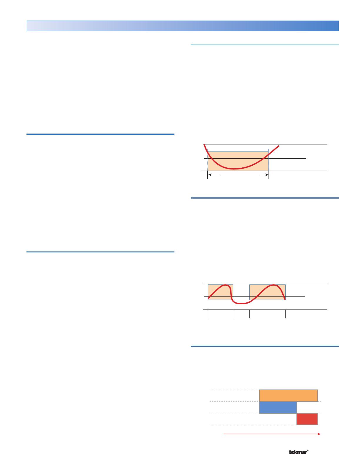
Boiler Minimum
The boiler minimum is the lowest temperature that the
control is allowed to use as a boiler target temperature.
During mild conditions, if the control calculates a boiler
target temperature that is below the Boiler Minimum setting,
the boiler target temperature is adjusted to at least the
Boiler Minimum setting. During this condition, if the boiler is
operating, the minimum segment is turned on in the display
when viewing either the boiler supply temperature or the
boiler target temperature. Set the Boiler Minimum setting
to the boiler manufacturer’s recommended temperature.
Locate the Boiler Minimum setting in the Adjust menu.
Boil MIN + ½ Boiler Differential
Boil MIN
Boil MIN– ½ Boiler Differential
MIN segment on
B
o
i
l
W
a
t
e
r
T
e
m
p
e
r
a
t
u
r
e
B
o
i
l
W
a
t
e
r
T
e
m
p
e
r
a
t
u
r
e
Boiler Maximum
The boiler maximum is the highest temperature that the
control is allowed to use as a boiler target temperature. If
the control does target the Boiler Maximum setting, and the
boiler temperature is near the boiler maximum temperature,
the maximum segment will be displayed in the LCD while
either the boiler target temperature or the boiler temperature
is being viewed. At no time does the control operate the
boiler above 248°F (120.0°C).
Locate the Boiler Maximum setting in the Adjust menu.
B
o
i
l
W
a
t
e
r
T
e
m
p
e
r
a
t
u
r
e
B
o
i
l
W
a
t
e
r
T
e
m
p
e
r
a
t
u
r
e
Boil MIN + ½ Boiler Differential
Boil MAX
Boil MIN – ½ Boiler Differential
MAX
segment
on
MAX
segment
on
Fire Delay
The Fire Delay is the time delay that occurs between the
time that the control closes the boiler contact to fire the
boiler and when the burner fires.
Locate the Fire Delay setting in the Adjust menu.
Boiler Contact Closed
Time
Fire Delay
Burner On
Boiler Temperature Control Section C
© 2007 D 422 - 08/07 20 of 32
On-Off Boiler Operation
If the heat source is an On-Off Boiler, the Boil On-Off / Mod
DIP switch must be set to On-Off.
Differential
An on / off heat source must be operated with a differential
in order to prevent short cycling. With the control, either
a fixed or an auto differential may be selected. The boiler
differential is divided around the boiler target temperature.
The boiler contact closes when the supply water temperature
is 1/2 of the differential setting below the boiler target
temperature. As the supply temperature reaches 1/2 of
the differential above the boiler target temperature, the
boiler is shut off.
Locate the Boiler Differential setting in the Adjust
menu.
Differential = 10°F (6°C)
Target + 1/2 Differential
Target – 1/2 Differential
Target
165°F (74°C)
160°F (71°C)
155°F (68°C)
Boiler
On
Boiler
On
Fixed Differential
If the user desires to have a fixed differential, this is set
using the Boiler Differential setting in the Adjust menu.
Auto Differential
In order to decrease temperature swings and increase boiler
efficiency, the Auto Differential feature automatically changes
the on / off differential of the boiler based on the heating
load. As the load increases, the differential will decrease to
minimize temperature swings. As the load decreases, the
differential will increase to prevent short cycling.
Off
Differential
Time
Heating Load
On
Modulating Boiler Operation
The 422 can operate a single hot-water modulating boiler.
This requires the use of the Mod (dc) output on the 422.
To operate a modulating boiler, the Boil On-Off / Mod DIP
switch must be set to Mod. The control operates the boiler
by first switching the boiler contact to allow the modulating
boiler to go through the ignition sequence (the boiler contact
may not be required on all modulating boilers). A 0-10 V (dc)
analog signal is used to modulate the boiler firing rate
from the Minimum Modulation setting using Proportional,
Integral and Derivative (PID) logic in order to satisfy the
boiler target temperature.
A modulating boiler requires all the same settings as an
on-off boiler in addition to the settings below.
Modulating Boiler Differential
A modulating boiler must be operated with a differential
while operating in low fire. The boiler differential is divided
around the boiler target temperature. The boiler burner
ignites at low fire when the supply water temperature is
1/2 of the Boiler Differential setting below the boiler target
temperature. The boiler is shut off in low fire as the supply
temperature reaches at least 1/2 of the differential above
the boiler target temperature. With the control, either a fixed
or an auto differential may be selected.
When the boiler is modulating above low fire, the differential
does not apply. Instead, the modulation output signal is
determined using Proportional, Integral and Derivative (PID)
logic in order to satisfy the boiler target temperature.
Boiler Motor Speed
The Boiler Motor Speed is the amount of time the boiler
requires to go from 0% modulation to 100% modulation.
Gas valve actuating motors have a design time from
fully closed to fully open which can be found in the
manufacturer’s manual. The Boiler Motor Speed should
be set to this time.
The Boiler Motor Speed setting for a Variable Frequency
Drive (VFD) is the amount of time required to go from a
stopped position to 100% fan speed. Since a VFD has a
very quick response rate, it may be necessary to increase
the Motor Speed setting in order to increase the stability
of the boiler modulation.
Locate the Boiler Motor Speed setting in the Adjust
menu.
  • Page 1 1
  • Page 2 2
  • Page 3 3
  • Page 4 4
  • Page 5 5
  • Page 6 6
  • Page 7 7
  • Page 8 8
  • Page 9 9
  • Page 10 10
  • Page 11 11
  • Page 12 12
  • Page 13 13
  • Page 14 14
  • Page 15 15
  • Page 16 16
  • Page 17 17
  • Page 18 18
  • Page 19 19
  • Page 20 20
  • Page 21 21
  • Page 22 22
  • Page 23 23
  • Page 24 24
  • Page 25 25
  • Page 26 26
  • Page 27 27
  • Page 28 28
  • Page 29 29
  • Page 30 30
  • Page 31 31
  • Page 32 32

tekmar Universal Reset Module 422 Installation guide

Type
Installation guide
This manual is also suitable for

Ask a question and I''ll find the answer in the document

Finding information in a document is now easier with AI