Page is loading ...

AD11
MAINBOARD
MANUAL
DOC No.: M00604
Rev. : A0
Date : 11, 2000
Part No. :25-11564-20

Handling Precautions
Warning:
1. Static electricity may cause damage to the integrated circuits on
the motherboard. Before handling any motherboard outside of its
protective packaging, ensure that there is no static electric charge
in your body.
2. There is a danger of explosion if the battery is incorrectly
replaced. Replace only with the same or an equivalent type
recommended by the manufacturer.
3. Discard used batteries according to the manufacturer’s
instructions.
4. Never run the processor without the heatsink properly and firmly
attached. PERMANENT DAMAGE WILL RESULT!
Observe the following basic precautions when handling the motherboard
or other computer components:
n Wear a static wrist strap which fits around your wrist and is
connected to a natural earth ground.
n Touch a grounded or anti-static surface or a metal fixture such as a
water pipe.
n Avoid contacting the components on add-on cards, motherboards,
and modules with the golden fingers connectors plugged into the
expansion slot. It is best to handle system components by their
monting brackets.
The above methods prevent static build-up and cause it to be discharged
properly.
Trademark
All trademarks mentioned in this manual are registered properly of
the respective owners.
Handling Precautions
This manual may not, in whole or in part, be photocopied, reproduced,
transcribed, translated, or transmitted in whatever form without the
written consent of the manufacturer, except for copies retained by the
purchaser for personal archival purposes.
Notice

i
Table of Contents
Table of Contents
Chapter 1 Overview
Package Checklist ......................................................................... 1-2
The AD11 Mainboard ............................................................... 1-3
Main Features ............................................................................... 1-4
ACPI Ready .................................................................................. 1-6
Chapter 2 Installation Procedures
Quick Reference (from Page 2-2 to 2-6).......................................... 2-2
Mainboard Layout.................................................................... 2-2
1). Clear CMOS, Clear Password, FSB Speed Select,
Auto Detect Freq. Ratio (ADD_EN, ADR),
Auto Detect CPU Core Voltage (ADV_EN, ADV) ............. 2-3
2). Front Panel Block Cable Connection............................ 2-6
3). CPU Fan Installation .................................................... 2-6
1). Set System Jumpers/Switches .................................................. 2-7
Clear CMOS: CLR_CMOS ................................................ 2-8
Clear Password: CLR_PSWD............................................ 2-8
FSB Speed Select: 100MHz/133MHz ................................. 2-9
Auto Detect CPU Core Voltage: ADV_EN ........................ 2-9
CPU Core Voltage Setting: ADV ....................................... 2-10
Auto Detect CPU Clock: ADR_EN ................................... 2-10
Bus Ratio Setting: ADR .................................................... 2-11
2). Install Memory Modules .......................................................... 2-12
3). Install the CPU ......................................................................... 2-12
4). Install Expansion Cards ............................................................ 2-14
5). Connect Devices ...................................................................... 2-15
Floppy Diskette Drive Connector: FDD ............................ 2-15
IDE HDD Device Connectors: PRIMARY, SECONDARY .. 2-16
ATX Power Connector: ATX_PWR1................................ 2-16
CPU Fan Connector: CPU_FAN ....................................... 2-17
System Case Fan Connector: CHS_FAN .......................... 2-17
Wake-On-Ring Connector: WOR...................................... 2-18
Wake-On-LAN Connector: WOL...................................... 2-18
System Chassis Open Alarm Connector: CHASSIS.......... 2-19

ii
AD11 Mainboard Manual
Blue Tooth Audio Port Connector: BT_AUDIO ............... 2-19
CD Audio-In Connectors: CD_IN1, AUX_IN.................... 2-20
Optional Audio Alert II Module Connector: NOVUS ....... 2-20
Infrared Connector: IR ...................................................... 2-21
Front Panel Block Connector: FPNL ................................. 2-22
PS/2 Keyboard and Mouse Connector: PS2_KB, PS2_MS 2-23
Universal Serial Bus Connectors: Rear USBs, Front USBs 2-23
Printer Connector: LPT ..................................................... 2-24
Serial Port Connectors: COM1, COM2 .............................. 2-24
Audio I/O Jacks: LINE_OUT, LINE_IN, MIC_IN,
FNT_AUDIO .................................................................... 2-25
Game/MIDI Connector: GAME ......................................... 2-25
Chapter 3 BIOS Setup
CMOS Setup Utility ...................................................................... 3-1
Standard CMOS Setup .................................................................. 3-2
Advanced BIOS Features ............................................................. 3-4
Advanced Chipset Features.......................................................... 3-8
Integrated Peripherals ................................................................... 3-12
Power Management Setup ............................................................ 3-18
PnP/PCI Configurations ................................................................ 3-22
PC Health Status ........................................................................... 3-24
Frequency/Voltage Control ........................................................... 3-25
Load Fail-Safe Defaults ................................................................. 3-26
Load Optimized Defaults ............................................................... 3-26
Supervisor/User Password............................................................ 3-27
Save and Exit Setup ....................................................................... 3-28
Exit without Saving ....................................................................... 3-28

1 - 1
Overview
Overview
Chapter 1
The new Socket A 1stMainboard AD11 is an ATX sized motherboard support-
ing the latest generation of AMD Athlon and Duron processors at industry
leading speeds. By utilizing DDR ( Double Data Rate ) transfer rate the 100/133
MHz AMD Athlon/Duron system bus effectively reaches speeds of 200/266
MHz. The AMD Athlon processor offers high-performance cache technology,
including 128KB of on-chip level one (L1) , while the Duron features full-
speed, on-chip L2 cache memory, and enhanced 3DNow!™ technology. The
1stMainboard AD11 has 2 memory module sockets for up to 1 GB of DDR
SDRAM (PC-200/266) is equipped with ECC memory support.
The 1stMainboard AD11 is based around the high performance that com-
prised of AMD 761 system controller for the North Bridge, and the VIA 686B
( Super South ). The chipset support for AGP 4x provides the end-user a
photo-realistic 3D experience suitable for the most robust 3D games and soft-
ware environments. Onboard AC97 sound ensures high quality audio, but
with the option of being disabled through the BIOS.
AD11 has 5 PCI (32 bit/33 MHz) slots. User can plug many kinds of PCI add-on
cards. The mainboard also has one CNR (Communication Networking Riser)
slot. The CNR slot on AD11 allows modem and audio add-on cards.

1 - 2
AD11 Mainboard Manual
IMPORTANT: AMD CPU HEAT SINK INSTALLATION
Be ware finish heat hink install. Before you boot system, please
check the heat sink is complete contact with die of CPU.
The poor contact will bring about over heat, it may damage your
processor.
It is strongly recommended that at least a 200-watt ATX power pupply
be used for this motherboard. Make sure that your ATX power sup-
ply can supply at least 20 amperes on teh +5-Volt lead and 10ma
on the +5-Volt standby lead (+5VSB). Your system may become
unstable / unreliable and may experience difficulty in powering up if
your power supply is inadequate.
In addition, the 1stMainboard AD11 is equipped with 2 dual channeled en-
hanced PCI bus master IDE connectors. Standard I/O connections include 2
serial ports, 1 parallel port, 1 PS/2 mouse and keyboard connector, 2 USB
connectors, 2 front USB pin-headers, and 1 media connector ( Line-In, Line-
Out, Mic-In, 1 Midi/game port).

1 - 3
Overview
The AD11 Mainboard

1 - 4
AD11 Mainboard Manual
Main Features
n Easy Installation
||BIOS with support for Plug and Play, auto detection of IDE hard drives,
||LS-120|drives, IDE ZIP drives, Windows 95, Windows 98, Windows ME,
||Windows NT, Windows 2000, |and OS/2.
n Leading Edge Chipset
AMD761 is a single-chip North Bridge for Socket A based Athlon/Duron
CPUs with 200 MHz Front Side Bus with AGP 4X and PCI plus advanced
memory controller that supports DDR SDRAM (PC-200/266).
VIA VT686B is a highly integrated I/O peripheral controller to achive a
PC99-compliant system. The 686B also supports the ATA-100 standards.
n Versatile Main Memory Support
Accepts up to 1 GB DDR SDRAM using two memory sockets for allowing
that from 64, 128, 256, 512MB with support for lightenning-fast DDR
SDRAM (PC-200/266).
n AMD® Athlon™ Processors Support
Duron Socket A CPU 600/650/700/750/800/850MHz and higher at 100MHz
FSB with AMD bus for double data transfer rate at 100MHz for an effective
200MHz transfer rate.
Athlon Socket A CPU 750/800/850/900/950MHz/1/1.1/1.2GHz at 100/
133MHz FSB with AMD Athlon bus for double data rate transfers at 100/
133MHz for effective 200/266MHz transfer rate.
n Enhanced PCI Bus Master IDE Controller with Ultra DMA 33/66/100
Support
Integrated Enhanced PCI Bus Master IDE controller features two dual-
channel connectors that up to four Enhanced IDE devices, including CD-
ROM and Tape Backup Drives, as well as Hard Disk Drives supporting
the new Ultra DMA 100 protocol. Standard PIO Mode 3, PIO Mode 4,
DMA Mode 2, DMA Mode 4, UltraDMA-100 Mode 5 devices are also
supported.

1 - 5
Overview
n CNR, AGP, and PCI Expansion Slots
One CNR audio/modem slot, one AGP Bus expansion slot, and five PCI
Bus expansion slots provided the room to install a full range of add-on
cards.
n Compact Onboard Audio Subsystem
Embeded in VIA 686B, an integrated PCI-mastering dual full-duplex di-
rect-sound AC97-link-compatible audio subsystem. Hardware sound
blaster pro and FM blocks are combined for MS Windows DOS box and
real mode DOS compatiblity. Loopback capability is implemented for
guiding audio streams into USB and 1394 speakers for digital sound.
n Super Multi Input/Output (I/O) Support
Integrated Plug and Play multi-I/O chipset features two high-speed UART
16550 compatible serial ports, one EPP/ECP capable parallel port, one
media connector (Mic-in, Line-in, Line-out, Midi/game port), and one FDD
connector.
n Convenient Rear Panel USB Connection Support
Two USB ports integrated in the rear I/O panel with two USB front panel
connections allow convenient and high-speed Plug and Play connec-
tions to the growing number of USB compliant peripheral devices on the
market.
n Onboard Accelerated Graphics Port (AGP)
The motherboard is installed one 32-bit AGP bus with a dedicated 66MHz/
133MHz path from the graphics card to the system memory offering much
greater bandwidth than the 32-bit PCI bus does. AGP enabled 3D graph-
ics cards can directly access main memory across this fast path instead of
using local memory. To make use of the improved AGP performance, the
motherboard should be installed with SDRAM type memory and the VGA
card and drivers should also be fully AGP compliant. Using Microsoft’s
Windows 98 and Windows 2000/ME which implement DirectDraw will
allow the system to take full use of AGP’s benefits without the need to
install additional drivers.

1 - 6
AD11 Mainboard Manual
ACPI Ready
This mainboard fully implements the new ACPI (Advanced Configuration and
Power Interface) 1.0B Hardware and BIOS requirement. If you install ACPI
aware of operating system, such as Windows 98, you fully utilized the power
saving under ACPI. (Windows ME/2000 Professional supports ACPI func-
tions.)

2 - 1
Installation Procedures
Chapter 2
Installation Procedures
The mainboard has several user-adjustable jumpers on the board that allow you to
configure your system to suit your requirements. This chapter contains information
on the various jumper settings on your mainboard.
To set up your computer, you must complete the following steps:
n Step 1 - Set system jumpers
n Step 2 - Install memory modules
n Step 3 - Install the Central Processing Unit (CPU)
n Step 4 - Install expansion cards
n Step 5 - Connect ribbon cables, cabinet wires, and power supply
n Step 6 - Set up BIOS software
n Step 7 - Install supporting software tools
WARNING: Excessive torque may damage the mainboard. When
using an electric screwdriver on the mainboard, make sure that
the torque is set to the allowable range of 5.0 ~ 8.0kg/cm.
Mainboard components contain very delicate Integrated Circuit
(IC) chips. To prevent static electricity from harming any of the
mainboard’s sensitive components, you should follow the
following precautions whenever working on the computer:
1. Unplug the computer when working on the inside.
2. Hold components by the edges and try not to touch the IC
||||chips, leads, or circuitry.
3. Wear an anti-static wrist strap which fits around the wrist.
4. Place components on a grounded anti-static pad or on the bag
that came with the component whenever the components are
separated from the system.

2 - 2
AD11 Mainboard Manual
Mainboard Layout
Quick Reference (from Page 2-2 to 2-6)

2 - 3
Installation Procedures
1). Clear CMOS, Clear Password,
FSB Speed Select,
Auto Detect Freq. Ratio (ADR_EN, ADR)
Auto Detect CPU Core Voltage (ADV_EN, ADV)

2 - 4
AD11 Mainboard Manual
NOTE: Please set the jumper ADV_EN at Disable before you adjust
the switch ADV.

2 - 5
Installation Procedures
NOTE: Please set the jumper ADR_EN at Disable before you ad-
just the switch ADR.

2 - 6
AD11 Mainboard Manual
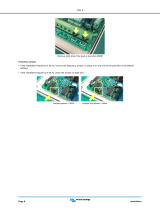
3). CPU Fan Installation
2). Front Panel Block Cable Connection
This connector is linked to the CPU fan. When the system is in suspend mode, the
CPU fan will turn off; when it reverts back to full on mode, the fan will turn back on.
Without sufficient air circulation, the CPU may overheat resulting in damage
to both the CPU and the mainboard.
Damage may occur to the mainboard and/or the CPU fan if these pins are
used incorrectly. These are not jumpers, do not place jumper caps over these
pins.

2 - 7
Installation Procedures
1). Set System Jumpers/Switches
Jumpers are used to select the operation modes for your system. Some jump-
ers on the board have three metal pins with each pin representing a different
function. A “1” is written besides pin 1 on jumpers with three pins. To set a
jumper, a black cap containing metal contacts is placed over the jumper pin/s
according to the required configuration. A jumper is said to be shorted when
the black cap has been placed on one or two of its pins. The types of jumpers
used in this manual are shown below:
NOTE: Users are not encouraged to change the jumper settings
not listed in this manual. Changing the jumper settings improperly
may adversely affect system performance.

2 - 8
AD11 Mainboard Manual
Clear CMOS: CLR_CMOS
The jumper allows you to enable or to disable the password setting. You may
need to adjust it if you forget your password. To clear the password setting:
(1).Turn off your computer, (2). Enable this feature by setting it at Enable, (3).
Turn on your computer to boot screen, (4). Turn off your computer, (5).
Disablethe Clear Password feature by setting at Disble, (6). Turn on your
computer. Press Delete key to load setup default values.
Clear Password: CLR_PSWD
This jumper allows you to enable or to disable the password configuration.
You may need to enable this jumper by shorting it with a jumper cap if you
forget your password. To clear the password setting: (1). Turn off your com-
puter, (2). Short this jumper by placing a jumper cap on it; (3). Turn on your
computer, (4). Hold down the Delete key during boot and enter BIOS Setup to
re-enter user preferences, (5). Turn off your computer, (6). Remove the jumper
cap, (7). Turn on your computer for the new settings to take effect.

2 - 9
Installation Procedures
FSB Speed Select: 100MHz/133MHz
The jumper allows users to select the front side bus speed.
Auto Detect CPU Core Voltage: ADV_EN
The 3-pin jumper allows the system to detect the processor core voltage auto-
matically when it stays at Enable.
WARNING: Voltage and frequency above CPU’s original specifi-
cations are not guaranteed to be stable.
NOTE: Please set the jumper ADV_EN at Disable before you adjust
the switch ADV.

2 - 10
AD11 Mainboard Manual
Auto Detect CPU Clock: ADR_EN
The 3-pin jumper allows the system to detect the processor clock automati-
cally when it stays at Enable; and allows users to set the CPU clock ratio when
they want to do so.
WARNING: Voltage and frequency above CPU’s original specifi-
cations are not guaranteed to be stable.
CPU Core Voltage Setting: ADV
The switch allows you to set the CPU core voltage to approach the best
performance according to the table below after you set the jumper ADV at
Disable.
1/64