
FCC Compliance Statement:
This equipment has been tested and found to
comply with limits for a Class B digital device,
pursuant to Part 15 of the FCC rules. These
limits are designed to provide reasonable
protection against harmful interference in
residential installations. This equipment
generates, uses, and can radiate radio
frequency energy, and if not installed and used
in accordance with the instructions, may cause
harmful interference to radio communications.
However, there is no guarantee that
interference will not occur in a particular
installation. If this equipment does cause
interference to radio or television equipment
reception, which can be determined by turning the equipment off and on, the
user is encouraged to try to correct the interference by one or more of the
following measures:
-Reorient or relocate the receiving antenna
-Move the equipment away from the receiver
-Plug the equipment into an outlet on a circuit different from that to which
the receiver is connected
-Consult the dealer or an experienced radio/television technician for
additional suggestions
You are cautioned that any change or modifications to the equipment not
expressly approve by the party responsible for compliance could void Your
authority to operate such equipment.
This device complies with Part 15 of the FCC Rules. Operation is subjected to
the following two conditions 1) this device may not cause harmful interference
and 2) this device must accept any interference received, including
interference that may cause undesired operation.
DECLARATION OF CONFORMITY
Per FCC Part 2 Section 2. 1077(a)
Responsible Party Name: G.B.T. INC.
Address: 18305 Valley Blvd., Suite#A
LA Puent, CA 91744
Phone/Fax No: (818) 854-9338/ (818) 854-9339
hereby declares that the product
Product Name:
Model Number:
Mother Board
Conforms to the following specifications:
FCC Part 15, Subpart B, Section 15.107(a) and Section 15.109(a),
Class B Digital Device
Supplementary Information:
This device complies with part 15 of the FCC Rules. Operation is subject to the
following two conditions: (1) This device may not cause harmful
and (2) this device must accept any inference received, including
that may cause undesired operation.
Representative Person's Name: ERIC LU
Signature:
Date: Jan. 12, 2000
Eric LuEric Lu
GA-7IXE

Declaration of Conformity
We, Manufacturer/Importer
(full address)
G.B.T. Technology Träding GMbH
Ausschlager Weg 41, 1F, 20537 Hamburg, Germany
declare that the product
( description of the apparatus, system, installation to which it refers)
Mother Board
GA-7IXE
is in conformity with
(reference to the specification under which conformity is declared)
in accordance with 89/336 EEC-EMC Directive
EN 55011 Limits and methods of measurement EN 61000-3-2* Disturbances in supply systems caused
of radio disturbance characteristics of EN60555-2 by household appliances and similar
industrial, scientific and medical (ISM electrical equipment “Harmonics”
high frequency equipment
EN55013 Limits and methods of measurement EN61000-3-3* Disturbances in supply systems caused
of radio disturbance characteristics of EN60555-3 by household appliances and similar
broadcast receivers and associated electrical equipment “Voltage fluctuations”
equipment
EN 55014 Limits and methods of measurement EN 50081-1 Generic emission standard Part 1:
of radio disturbance characteristics of Residual, commercial and light industry
household electrical appliances,
portable tools and similar electrical EN 50082-1 Generic immunity standard Part 1:
apparatus Residual, commercial and light industry
EN 55015 Limits and methods of measurement EN 55081-2 Generic emission standard Part 2:
of radio disturbance characteristics of Industrial environment
fluorescent lamps and luminaries
EN 55020 Immunity from radio interference of EN 55082-2 Generic immunity standard Part 2:
broadcast receivers and associated Industrial environment
equipment
EN 55022 Limits and methods of measurement ENV 55104 Immunity requirements for household
of radio disturbance characteristics of appliances tools and similar apparatus
information technology equipment
DIN VDE 0855 Cabled distribution systems; Equipment EN 50091- 2 EMC requirements for uninterruptible
part 10 for receiving and/or distribution from power systems (UPS)
part 12 sound and television signals
CE marking (EC conformity marking)
The manufacturer also declares the conformity of above mentioned product
with the actual required safety standards in accordance with LVD 73/23 EEC
EN 60065 Safety requirements for mains operated EN 60950 Safety for information technology equipment
electronic and related apparatus for including electrical business equipment
household and similar general use
EN 60335 Safety of household and similar EN 50091-1 General and Safety requirements for
electrical appliances uninterruptible power systems (UPS)
Manufacturer/Importer
Signature
:
Rex Lin
(Stamp)
Date: Jan. 12, 2000 Name : Rex Lin

R-11-01-000106
7IXE
AMD
TM
Athlon AGP Motherboard
USER'S MANUAL
AMD
TM
Athlon Processor Motherboard
REV. 1.1 First Edition

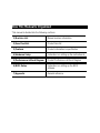
How This Manual Is Organized
This manual is divided into the following sections:
1) Revision List
Manual revision information
2) Item Checklist
Product item list
3) Features
Product information & specification
4) Hardware Setup
Instructions on setting up the motherboard
5) Performance & Block Diagram
Product Performance & Block Diagram
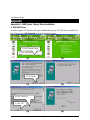
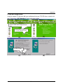
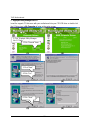
6) BIOS Setup
Instructions on setting up the BIOS
software
7) Appendix
General reference

Table Of Content
Revision History P.1
Item Checklist P.2
Summary of Features P.3
7IXE Motherboard Layout P.5
Page Index for Connectors / Panel and Jumper Definition P.6
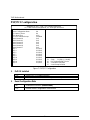
Performance List P.19
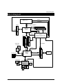
Block Diagram P.20
Memory Installation P.21
Page Index for BIOS Setup P.22
Appendix P.55


7IXE Motherboard
1
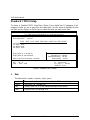
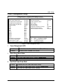
Revision History
Revision Revision Note Date
1.1 Initial release of the 7IXE motherboard user’s manual. Jan.2000
The author assumes no responsibility for any errors or omissions that may appear in this
document nor does the author make a commitment to update the information contained herein.
Third-party brands and names are the property of their respective owners.
Jan. 6, 2000 Taipei, Taiwan, R.O.C

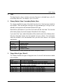
Item Checklist
2
Item Checklist
þThe 7IXE Motherboard
þCable for IDE / Floppy device
þDiskettes or CD (TUCD) for motherboard utilities
oInternal COM2 Cable (Optional)
oInternal USB Cable (Optional)
oCable for SCSI device
þ7IXE User’s Manual

7IXE Motherboard
3
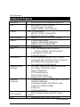
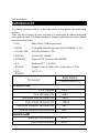
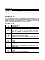
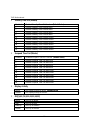
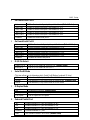
Summary Of Features
Form factor
Ÿ 26 cm x 18 cm ATX SIZE form factor, 4 layers PCB.
CPU Ÿ AMD Athlon(K7) Slot A Processor
Ÿ 512 KB 2nd cache in CPU Module
Ÿ Supports 500MHz ~ 1GHz and faster
Chipset AMD
750 ,consisting of:
Ÿ AMD 751 PCI/AGP Controller(PAC)
Ÿ AMD 756 PCI ISA IDE Controller
Clock Generator Ÿ Supports 90 / 95 / 100 / 105 / 110 / 115MHz
Memory Ÿ 3 168-pin DIMM Sockets
Ÿ Supports SDRAM 16MB~768MB(Max)
Ÿ Supports only 3.3V SDRAM DIMM
I/O Control Ÿ Winbond 83977
Slots Ÿ 1 AGP (Accelerated Graphics Port) slot
- AGP 66 / 133 MHz 3.3V device support
Ÿ 5 32-bit Master PCI Bus slots
Ÿ 2 16-bit ISA Bus slots
On-Board IDE Ÿ An IDE controller on the AMD 756 PCI chipset
provides IDE HDD/ CD-ROM with PIO, Bus Master ,
Ultra DMA33/ATA 66 Operation modes
Ÿ Can connect up to four IDE devices
Hardware Monitor
(Optional)
Ÿ CPU/Power Supply/System Fan Revolution detect
Ÿ CPU / Power / System Fan Control
Ÿ System Voltage Detect
Ÿ CPU Overheat Warning
Ÿ Chassis Intrusion Detect
Ÿ Display Actual Current Voltage
On-Board
Peripherals
Ÿ 1 Floppy port supports 2 FDD with 360K, 720K,1.2M,
1.44M and 2.88M bytes
Ÿ 1 Parallel port supports SPP/EPP/ECP mode
Ÿ 2 Serial Ports (COMA & COMB)
Ÿ 4 USB ports
Ÿ 1 IrDA connector for IR
PS/2 Connector
Ÿ PS/2
Keyboard interface and PS/2
Mouse
interface
BIOS Ÿ Licensed AMI BIOS, 2M bit FLASH ROM
To be continued…

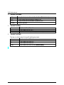
Summary of Features
4
Additional Features Ÿ Internal/External Modem Wake up
Ÿ Keyboard Password Wake up
Ÿ Mouse Wake up
Ÿ LAN Wake up
Ÿ System after AC back

7IXE Motherboard
5
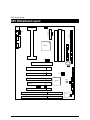
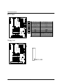
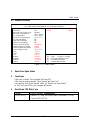
7IXE Motherboard Layout
7IXE
PCISLOT1
PCISLOT2
PCISLOT3
PCISLOT4
ATX POWER
JP2
AMD751
FLOPPY
PS/2
USB
AGP
AMD756
ISA1
ISA2
J22
J6
JP1
BAT1
PCISLOT5
J9
JP4
JP9
JP5
JP10
BZ1
BIOS
JP12
SW1

7IXE Motherboard Layout
6

7IXE Motherboard
7
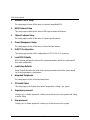
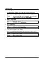
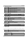
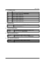
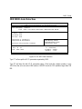
$ Page Index for Connectors / Panel and Jumper Definition Page
Connectors P.8
COMA / COMB / LPT Port P.8
USB Connector P.8
PS/2 Keyboard & PS/2 Mouse Connector P.9
Power Cooling FAN Power Connector P.9
CPU / System Cooling FAN Power Connector P.10
ATX Power P.11
Floppy Port P.11
IDE 1(Primary) / IDE 2(Secondary) Port P.12
USB Port P.12
IR (Optional) P.13
JP9 (Ring Power On) P.13
JP4 (Wake On LAN) P.14
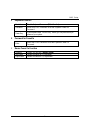
Panel and Jumper Definition P.15
J22 (2x11 pins jumper) P.15
JP10 (PS/2 Keyboard Power On) P.16
JP1 (Case Open) P.16
JP12 (BIOS Flash ROM Write Protection) P.17
JP5 (Internal Buzzer Connector)[Optional] P.17
JP3 (Clear CMOS) P.18
BAT 1 P.18


7IXE Motherboard
7
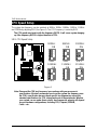
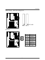
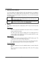
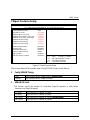
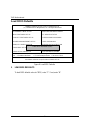
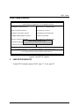
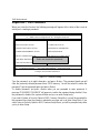
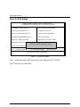
CPU Speed Setup
The system bus frequency can be switched at 90MHz, 95MHz, 100MHz, 105MHz, 110MHz
and 115MHz by adjusting SW1 (See Figure 1). The CPU Frequency is control by BIOS.
MM The CPU speed must match with the frequency RATIO. It will cause system hanging
up if the frequency RATIO is higher than that of CPU.
SW1: CPU Speed Setup
SW1
ON
1
2
3
4
90MHz
SW1
ON
1
2
3
4
95MHz
SW1
ON
1
2
3
4
100MHz
SW1
ON
1
2
3
4
105MHz
SW1
ON
1
2
3
4
110MHz
SW1
ON
1
2
3
4
115MHz
Figure 1
««Note: Please set the CPU host frequency in accordance with your processor’s
specifications. We don’t recommend you to set the system bus frequency over
the CPU’s specification because these specific bus frequencies are not the
standard specifications for CPU, chipset and most of the peripherals. Whether
your system can run under these specific bus frequencies properly will depend
on your hardware configurations, including CPU, Chipsets, SDRAM,
Cards….etc.

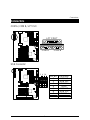
Connectors
8
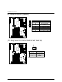
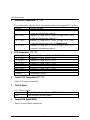
Connectors
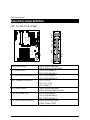
COM A / COM B / LPT Port
COM A
COM B
LPT PORT
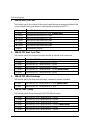
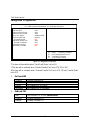
USB Connector
Pin No.
Definition
1 USB V0
2 USB D0-
3 USB D0+
4 GND
5 USB V1
6 USB D1-
7 USB D1+
8 GND
1
2
3
4
8
7
6
5

7IXE Motherboard
9
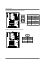
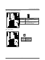
PS/2 Keyboard & PS/2 Mouse Connector
PS/2 Mouse/ Keyboard
Pin No.
Definition
1 Data
2 NC
3 GND
4 VCC(+5V)
5 Clock
6 NC
PS/2 Keyboard
PS/2 Mouse
1
2
3
4
5
6
Power Cooling FAN Power Connector
Pin No. Definition
1 GND
2 +12V
3 SENSE
1

Connectors
10
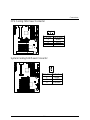
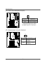
CPU Cooling FAN Power Connector
Pin No. Definition
1 GND
2 +12V
3 SENSE
1
System Cooling FAN Power Connector
Pin No. Definition
1 GND
2 +12V
3 SENSE
1

7IXE Motherboard
11
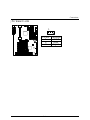
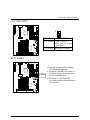
ATX Power
Pin No. Definition
3,5,7,13,15-17
GND
1,2,11 3.3V
4,6,19,20 VCC
10 +12V
12 -12V
18 -5V
8 Power Good
9 5V SB stand by+5V
14 PS-ON(Soft On/Off)
10
11
20
1
Floppy Port
RED LINE

Connectors
12
IDE1(Primary) , IDE2 (Secondary) Port
IDE 1
RED LINE
IDE 2
USB Port
Pin No.
Definition
1 VCC
2
USB D0
−
3 USB D0+
4 GND
5 VCC
6
USB D1
−
7 USB D1+
8 GND
1
4
5
8
Page is loading ...
Page is loading ...
Page is loading ...
Page is loading ...
Page is loading ...
Page is loading ...
Page is loading ...
Page is loading ...
Page is loading ...
Page is loading ...
Page is loading ...
Page is loading ...
Page is loading ...
Page is loading ...
Page is loading ...
Page is loading ...
Page is loading ...
Page is loading ...
Page is loading ...
Page is loading ...
Page is loading ...
Page is loading ...
Page is loading ...
Page is loading ...
Page is loading ...
Page is loading ...
Page is loading ...
Page is loading ...
Page is loading ...
Page is loading ...
Page is loading ...
Page is loading ...
Page is loading ...
Page is loading ...
Page is loading ...
Page is loading ...
Page is loading ...
Page is loading ...
Page is loading ...
Page is loading ...
Page is loading ...
Page is loading ...
Page is loading ...
Page is loading ...
Page is loading ...
Page is loading ...
Page is loading ...
Page is loading ...
Page is loading ...
Page is loading ...
Page is loading ...
Page is loading ...
Page is loading ...
-
 1
1
-
 2
2
-
 3
3
-
 4
4
-
 5
5
-
 6
6
-
 7
7
-
 8
8
-
 9
9
-
 10
10
-
 11
11
-
 12
12
-
 13
13
-
 14
14
-
 15
15
-
 16
16
-
 17
17
-
 18
18
-
 19
19
-
 20
20
-
 21
21
-
 22
22
-
 23
23
-
 24
24
-
 25
25
-
 26
26
-
 27
27
-
 28
28
-
 29
29
-
 30
30
-
 31
31
-
 32
32
-
 33
33
-
 34
34
-
 35
35
-
 36
36
-
 37
37
-
 38
38
-
 39
39
-
 40
40
-
 41
41
-
 42
42
-
 43
43
-
 44
44
-
 45
45
-
 46
46
-
 47
47
-
 48
48
-
 49
49
-
 50
50
-
 51
51
-
 52
52
-
 53
53
-
 54
54
-
 55
55
-
 56
56
-
 57
57
-
 58
58
-
 59
59
-
 60
60
-
 61
61
-
 62
62
-
 63
63
-
 64
64
-
 65
65
-
 66
66
-
 67
67
-
 68
68
-
 69
69
-
 70
70
-
 71
71
-
 72
72
-
 73
73


