
OM26K
Water Softening System
INSTALLATION INSTRUCTIONS
English .............................. Pages 2-19
Repair Parts. . . . . . . . . . . . . . . . . . . . . . . . . . . . .Page 13
Sistema de ablandamiento de agua
INSTRUCCIONES DE INSTALACIÓN
Español .......................... Páginas 20-37
Piezas de repuesto ..................... Página 32
Systeme d'adoucissement d'eau
INSTRUCTIONS D’INSTALLATION
Français ............................ Pages 38-55
Piéces de Rechange ..................... Page 50
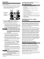
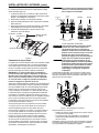
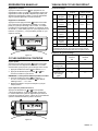
Tools and Fittings Required
• Pipe Cutter
• Tubing Cutter
• File
• Pliers
• Tape Measure
• Soldering Tools
• Lead Free Solder
• Bucket
• Towel
• PTFE Pipe Tape
• Adjustable Wrench
• Tube 100% Silicone Grease
Outils et accessoires requis
• Coupe-tuyau
• Coupe-tube
• Lime
• Pince
• Mètre ruban
• Outillage de brasage
• Brasure sans plomb
• Seau
• Serviette
• Ruban pour tuyau en PTFE
• Clé ajustable
• Graisse de silicone à 100 %
pour tube
For further operating, installation, maintenance,
parts or assistance:
Call OMNIFILTER Customer Service at:
800.279.9404
Para obtener más información sobre el
funcionamiento, la instalación, el mantenimiento,
las piezas o para obtener asistencia:
Comuníquese con el Servicio de atención
al cliente de OMNIFILTER al: 800.279.9404
Pour de tout autre renseignement concernant
le fonctionnement, l’installation ou l’entretien:
Appelez le service à la clientèle en com-
posant le: 800.279.9404
Herramientas y accesorios
necesarios
• Sierra para cortar tuberías
• Cortatubos
• Lima
• Pinzas
• Cinta métrica
• Herramientas para soldar
• Soldador libre de plomo
• Cubeta
• Toalla
• Cinta de PTFE para tubería
• Llave ajustable
• Tubo de grasa 100% de silicona
Tested and Certied by WQA to NSF/
ANSI Standard 44 & 372 for softener
performance & lead free compliance and
CSA B483.1.
Probado y certicado por la WQA
según la norma 44 y 372 de NSF/ANSI
por el desempeño del suavizador y el
cumplimiento del no contenido de plomo
y CSA B483.1.
Testé et certié par WQA conforme
à la norme 44 et à la norme 372 de
NSF/ANSI pour la perfomance des
adoucisseurs et pour la conformité à
l'exemption de plomb et CSA B483.1.
13845 Bishops Dr., Suite 200, Brookfield, WI 53005
Phone: 800.279.9404 www.OMNIFILTER
.com

TABLE OF CONTENTS
MANUAL OVERVIEW ............................................................2
PARTS INCLUDED ................................................................2
EQUIPMENT INSTALLATION ................................................3
CONTROL OPERATION & LAYOUT ......................................9
PROGRAMMING ....................................................................10
MANUAL REGENERATION ...................................................11
QUICK CYCLING THE CONTROL .........................................11
CYCLE DEFAULTS TABLE ....................................................11
START-UP ..............................................................................12
INSTALLATION CHECKLIST .................................................12
CARE AND USE OF YOUR BRINE TANK .............................12
SYSTEM DISINFECTION ......................................................12
ACCESSING HISTORY VALUES ...........................................13
TANK ASSEMBLY ..................................................................13
VALVE ASSEMBLY .................................................................14
BRINE WELL ASSEMBLY CH15675 ......................................15
TROUBLESHOOTING ...........................................................16
PENTAIR RESIDENTIAL FILTRATION, LLC LIMITED
WARRANTY ..........................................................................18
PERFORMANCE DATA SHEET .............................................19
MANUAL OVERVIEW
How To Use This Manual
This installation manual is designed to guide the installer
through the process of installing and starting the OM26K
softener.
This manual is a reference and will not include every system
installation situation. The person installing this equipment
should have:
• Knowledge in the water softener installation
• Basic plumbing skills
Icons That Appear In This Manual
WARNING:
Failure to follow this instruction can result in
personal injury or damage to the equipment.
NOTE: This will make the process easier if followed.
Inspection
Inspect the unit for damage or missing parts.
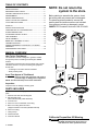
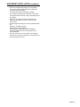
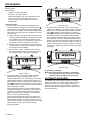
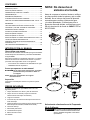
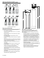
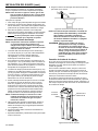
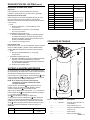
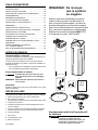
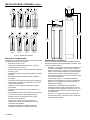
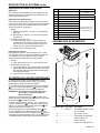
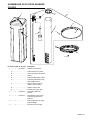
PARTS INCLUDED
The OM26K Water Softening System should have the following
parts:
1. Softener Tank with Valve and Bypass
2. Salt Tank with Cover
(Brine Well Assembly Inside Salt Tank)
3. Connector Kit
4. Drain Line Flow Control/Drain Line Fitting
5. Brine Line Tubing with End Inserts
(shipped inside the brine well (installed inside #2)
6. Drain Line Tubing
7. Tubing Clamp
8. Wall Transformer
9. Instruction Manual
NOTE: Do not return the
system to the store.
Before starting to assemble the system, check
that all the parts are present and not damaged.
The plumbing pieces needed to connect the
water system and softener salt are not included.
If any parts are missing or damaged, contact
OMNIFILTER Customer Service at: 800.279.9404.
1
8
OM26K
Manual
9
6
7
5
4
3
2
California Proposition 65 Warning
WARNING:
This product contains chemicals known to
the State of California to cause cancer or
birth defects or other reproductive harm.
2 • OM26K

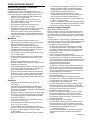
EQUIPMENT INSTALLATION
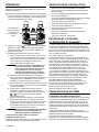
General Warnings And Safety Information
Electrical
There are no user-serviceable parts in the AC adapter, motor,
or controller. In the event of a failure, these should be replaced.
• All electrical connections must be completed according to
local codes.
• Use only the power AC adapter that is supplied. If the AC
adapter is replaced use a Class II, 12 volt, 150 mA supply.
• The power outlet must be grounded and always on.
• To disconnect power, unplug the AC adapter from its
power source.
• Install an appropriate grounding strap across the inlet
and outlet piping of the water system to ensure proper
grounding is maintained.
Mechanical
• Do not use petroleum based lubricants such as vaseline,
oils, or hydrocarbon based lubricants. Use only 100%
silicone lubricants.
• All plastic connections should be hand tightened.
Plumber's tape should be used on connections that do not
use an O-ring seal. Do not use pliers or pipe wrenches.
• All plumbing must be completed according to local codes.
• Soldering of the plumbing should be done before
connecting to the valve. Excessive heat will cause interior
damage to the valve.
• Observe drain line requirements.
• Do not use lead-based solder for sweat solder
connections.
• The drain line must be a minimum of 1/2-inch diameter.
Use 3/4-inch pipe if the pipe length is greater than
20 feet (6 m).
• Do not support the weight of the system on the control
valve ttings, plumbing, or the bypass.
• It is not recommended to use sealants on the threads.
Use plumber's tape on all NPT threads.
General
• Observe all warnings that appear in this manual.
• This system is not intended to be used for treating water
that is microbiologically unsafe or of unknown quality
without adequate disinfection before or after the system.
• Keep the unit in the upright position. Do not turn on side,
upside down, or drop. Turning the tank upside down will
cause media to enter the valve.
• Operating ambient temperature is between 34°F (1°C)
and 120°F (49°C).
• Operating water temperature is between 35°F (1°F) and
100°F (38°C).
• Working water pressure range is 20 to 125 psi
(1.38 to 8.61 bar). In Canada the acceptable working
water pressure range is 20 to 100 psi (1.38 to 6.89 bar).
• Use only salts designed for water softening. Acceptable
salt type is sodium chloride pellet salt.
• Follow state and local codes for water testing. Do not
use water that is microbiologically unsafe or of unknown
quality.
• When lling media tank, do not open water valve
completely. Fill tank slowly to prevent media from exiting
the tank.
• Always make modications to house plumbing rst.
Connect to valve last.
• Plastic parts and O-rings may be damaged by heat and
solvents. When constructing plumbing connections allow
heated parts to cool and protect parts from solvents.
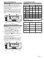
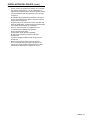
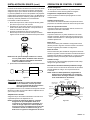
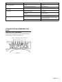
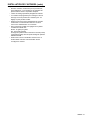
System Recharge Cycles
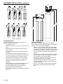
Service (Downow):
Untreated water is directed down through the resin bed and up
through the riser tube. The hardness ions attach themselves
to the resin and are removed from the water. The water is
conditioned as it passes through the resin bed.
When a recharge cycle starts, the softener goes through
seven cycles. During the recharge cycle the softener will allow
untreated water to bypass into the building.
1. Backwash 1 (Upow):
The ow of water is reversed by the control valve and
directed down the riser tube and up through the resin bed.
During the backwash cycle, the bed is expanded and debris
is ushed to the drain.
2. Brine Draw (Downow):
The brine draw cycle takes place during the slow rinse
cycle. The control directs water through the brine injector
and brine is drawn from the salt tank. Brine draw is
completed when the air check in the salt tank closes.
Slow Rinse (Downow):
The brine is directed down through the resin bed and up
through the riser tube to the drain. The hardness ions are
displaced by sodium ions and are sent to the drain. The
resin is recharged during the brine cycle.
3. Repressurize Cycle (Hard Water Bypass Flapper Open):
This cycle closes the appers for a short time to allow the
air and water to hydraulically balance in the valve before
continuing the recharge.
4. Fast Rinse 1 (Downow):
The control directs water down through the resin bed and
up through the riser tube to the drain. Any remaining brine
residual is rinsed from the resin bed.
5. Backwash 2 (Upow):
The ow of water is reversed by the control valve and
directed down the riser tube and up through the resin bed.
During the backwash cycle, the bed is expanded and debris
is ushed to the drain.
6. Fast Rinse 2 (Downow):
The control directs water down through the resin bed and
up through the riser tube to the drain. Any remaining brine
residual is rinsed from the resin bed.
7. Brine Rell:
Water is directed to the salt tank at a controlled rate, to
create brine for the next recharge.
OM26K • 3

To Regenerant
Tank
BRINE REFILL
Cycle 7
FAST RINSE
Cycle 4
BACKWASH
Cycle 5
FAST RINSE
Cycle 6
SERVICE
BACKWASH
Cycle 1
REPRESSURIZE
Cycle 3
From Regenerant
Tank
BRINE/SLOW RINSE
Cycle 2
Figure 1 Flow Patterns
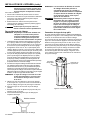
Location Selection
Location of a water treatment system is important. The
following conditions are required:
• Level platform or oor.
• Ambient temperatures over 34°F (1°C) and below 120°F
(49°C).
• Water pressure below 125 psi (8.61 bar) and above
20 psi (1.4 bar).
• In Canada the water pressure must be below 100 psi
(6.89 bar).
• Constant electrical supply to operate the controller.
• Total minimum pipe run to water heater of ten feet (three
meters) to prevent backup of hot water into system.
• Local drain or tub for discharge as close as possible.
• Water line connections with shutoff or bypass valves.
• Must meet any local and state codes for site of
installation.
• Valve is designed for minor plumbing misalignments. Do
not support weight of system on the plumbing.
• Be sure all soldered pipes are fully cooled before
attaching plastic valve to the plumbing.
• Room to access equipment for maintenance and adding
salt to tank.
8.8 in
(22.3 cm)
4 in
(10.1 cm)
46.5 in
(118.1 cm)
48.3 in
(122.6 cm
)
11.3 in
(28.7 cm)
36.5 in
(92.7 cm)
Outdoor Locations
It is recommended that the OM26K system be installed
indoors. When the water conditioning system must be installed
outdoors, several items must be considered.
• Moisture — The valve and controller are rated for NEMA
3 locations. Falling water should not affect performance.
The system is not designed to withstand extreme humidity
or water spray from below. Examples are: constant heavy
mist, near corrosive environment, upwards spray from
sprinkler.
• Direct Sunlight — The materials used will fade or discolor
over time in direct sunlight. The integrity of the materials
will not degrade to cause system failures.
• Temperature — Extreme hot or cold temperatures may
cause damage to the valve or controller.
Freezing temperatures will freeze the water in the valve.
This will cause physical damage to the internal parts as
well as the plumbing.
• Insects — The controller and valve have been designed
to keep all but the smallest insects out of the critical
areas.
EQUIPMENT INSTALLATION continued
4 • OM26K

Things You Need to Know
• When the controller is rst plugged in, it may display
an Err 3, this means that the controller is rotating the
camshaft to the home position.
• The preset default time of recharge is 2:00 AM.
• The controller is programmed to recharge if a recharge
has not taken place in the last 7 days. This setting cannot
be changed.
• Make sure control power source is plugged in. The
transformer should be connected to a non-switched
power source.
• Unless changed, the settings for a newly installed system
are:
Hardness - 25 grains per gallon
Salt Setting - HC (High Capacity)
Internal System clock starts at 0 hours (midnight)
The rst recharge will occur when the system clock
reaches 2:00 AM
• Test your water. Take a 4-5 oz sample of your water to
someone who can test for hardness. This information will
be used to setup the control.
EQUIPMENT INSTALLATION continued
OM26K • 5

Grounding the Plumbing
It is important that the plumbing system be electrically
grounded. When a water softener is installed a non-metalic
bypass valve may interrupt the grounding. To maintain
continuity, a grounding strap can be purchased at a hardware
store. When it is installed the strap will connect the plumbing
into the softener to the plumbing out of the softener.
If you have other water treating equipment such as; chlorinator,
sediment lter, neutralizer, iron lter, or taste & odor lter they
should be installed upstream of the water softener.
You may wish to consult a water professional if additional water
treating equipment is to be installed.
EQUIPMENT INSTALLATION continued
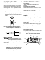
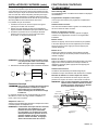
Valve Layout
Outlet 1" NPT
Inlet 1" NPT
Meter
Cable
Drain
1/2" Tube
To Brine Tank
3/8" NPT
Figure 4
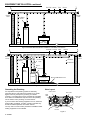
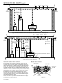
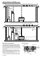
Laundry Tubs
Pump
or
Meter
Hot Water
Outlet
Outside
Faucet
Outside
Faucet
Water
Heater
Bath Tub Lavatory Toilet Kitchen
Floor Drain
Figure 2 Standard Basement Before Installation. Cold Water Lines Shown
Soft Water
Hard Water
Outside
Faucet
Outside
Faucet
Bath TubLavatoryToilet Kitchen
Laundry Tubs
Pump
or
Meter
Hot Water
Outlet
Water
Heater
Brine Tank Overow Drain
Floor Drain
Drain Line
Bypass
Softener
Grounding
Strap
Figure 3 Softened Water Flow
6 • OM26K

EQUIPMENT INSTALLATION continued
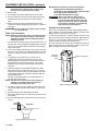
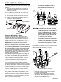
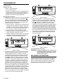
Drain Line Flow Control
The drain line ow control (DLFC) requires assembly
(Figure 5).
1. Locate parts and a roll of plumber's tape.The plumbing
adapters should be removed (Figure 7 Connector
Assembly).
2. Wrap the tape over threads of the ow control.
3. Screw the ow control and the 90° elbow together. Hand
tighten.
4. Place the ball into the ow control and insert the assembly
into the drain line opening.
5. Push the assembly in and secure with the drain line clip.
90° Elbow
Flow Control
Control Ball
Drain Line Clip
Figure 5
Water Line Connection
A bypass valve system is included and will be installed on the
water conditioning system. Bypass valves isolate the softener
from the water system and allow unconditioned water to be
used. Service or routine maintenance procedures may also
require that the system is bypassed.
IMPORTANT: The bypass valve is shipped to you in the
bypass position (Figure 6 Bypass Operation). When the
valve is in bypass water will not enter the softening tank.
The water in the building will not be treated. Figure 6
Bypass Operation, shows the handles in the service
position.
Once you have selected your location check the direction of
the waterow in the main pipe. Figure 6 Bypass Operation can
be used to plan the new plumbing assembly.
Inspect the main water pipe. Write down the type of pipe
(copper, plastic, galvanized etc.). Record the size of the pipe.
Plastic style pipes usually have the size printed on the outside.
Other pipes can be measured for the outside diameter and
converted into the pipe size at the store. Do not use pipe that is
smaller than the main water pipe.
The bypass has two ttings that connect to the plumbing.
These connections are threaded 1" NPT.
If the main plumbing is galvanized pipe and you are installing
copper pipe, then you must use dielectric insulating connectors
between the two styles of pipe.
Place the two tanks in position. The design of the tank does not
allow for bad alignment of the connections. You may ask your
supply store about exable connections.
Take measurements and create a drawing of your installation.
Include pipe lengths and elbows that are needed. If the water
ow is from right to left you will need to cross the plumbing to
the softener. Take the drawing to your plumbing supply store.
Consult with their expert for installation ideas and suggestions.
Assemble the plumbing.
WARNING:
If pipes will be sweat soldered, do not
connect adapters to the bypass until the
pipes have cooled.
IN OUT
IN OUT
Connector
Assembly
“H” Clip
Drain
Line
Handles in Service Handles in Bypass
Figure 6 Bypass Operation
WARNING:
The inlet water must be connected to the
inlet port of the valve. When replacing
non-Omni Water valves, it is possible that
the inlet and outlet plumbing is installed
in a reversed position. Be certain the inlet
connection on the valve is connected to the
incoming water tting from the water supply.
Do not solder pipes with lead-based solder.
WARNING:
Do not use petroleum grease on gaskets
when connecting bypass plumbing. Use
only 100% silicone grease products when
installing any plastic valve. Non-silicone
grease may cause plastic components to fail
over time.
The bypass assembly connects to the water system by means
of a connector assembly. The connector is secured to the
plumbing and then inserted into the bypass. A clip is used to
hold it in place.
Figure 7 Connector Assembly
Before inserting the connector:
• Check that all O-rings are in place and not damaged.
• O-rings are pre-lubricated. Sliding surfaces should be
lubricated with 100% silicone grease.
Firmly insert connector into bypass. Press locking clip into
position. Make certain the clip is fully engaged.
OM26K • 7

NOTE: Before turning on the water to the valve, rotate the
two handles on the bypass valve 2-3 times. This
will help seat O-rings and prevent leaking.
To remove a clip:
1. Turn off water and release water pressure at the valve.
2. Push the water line connectors into the bypass and valve.
This will help release O-rings that may have seated in
place.
3. Remove the clip by inserting a at blade under the top
center of the clip and lifting (prying up) (Figure 7 Connector
Assembly).
WARNING:
Do not use pliers to remove a clip. It is likely
the clip will break.
Drain Line Connection
NOTE: Standard commercial practices are expressed here.
Local codes may require changes to the following
suggestions. Check with local authorities before
installing a system.
1. The unit should be above and not more than 20 feet (6.1 m)
from the drain. Use an appropriate adapter tting to connect
1/2-inch (1.3 cm) plastic tubing to the drain line connection
of the control valve.
2. If the unit is located 20-40 feet (6.1-12.2 m) from drain, use
3/4-inch (1.9 cm) tubing. Use appropriate ttings to connect
the 3/4-inch tubing to the 3/4-inch NPT drain connection on
valve.
3. The drain line may be elevated up to 6 feet (1.8 m)
providing the run does not exceed 15 feet (4.6 m) and
water pressure at the softener is not less than 40 psi (2.76
bar). Elevation can increase by 2 feet (61 cm) for each
additional 10 psi (.69 bar) of water pressure at the drain
connector.
4. Where the drain line is elevated but empties into a drain
below the level of the control valve, form a 7-inch (18-cm)
loop at the far end of the line so that the bottom of the loop
is level with the drain line connection. This will provide an
adequate siphon trap.
Where the drain empties into an overhead sewer line, a
sink-type trap must be used.
NOTE: The drain line connects to the elbow previously
installed. It is located between the water line
connections at the rear of the valve.
5. Use pliers to expand a clamp. Slide the clamp up one end
of the longer length drain line tubing about 1-2 inches and
release.
6. Push the tubing over the ribbed drain line tting.
7. Expand the clamp and move it up the tube to pinch the tube
to the ftitting.
8. Secure the discharge end of the drain line to prevent it from
moving.
Right Way
Figure 8 Drain Line Connection
NOTE:
Waste connections or drain outlet shall be
designed and constructed to provide for
connection to the sanitary waste system through
an air-gap of 2 pipe diameters or
1 inch (22 mm) whichever is larger.
WARNING:
Never insert drain line directly into a
drain, sewer line, or trap (Figure 8 Drain
Line Connection). Always allow an air gap
between the drain line and the wastewater
to prevent the possibility of sewage being
back-siphoned into the softener.
Overow Line Connection
In the event of a malfunction, the salt TANK OVERFLOW will
direct “overow” to the drain instead of spilling on the oor. This
tting should be on the side of the cabinet.
To connect the overow line, locate the tubing connector on the
side of the tank (Figure 9 Tubing Connections). Attach length of
1/2-inch (1.3-cm) I.D. tubing to tting and run to drain. Do not
elevate overow line higher than overow tting.
Do not tie into drain line of control unit. Overow line must be a
direct, separate line from overow tting to drain, sewer or tub.
Allow an air gap as per drain line instructions.
Overow
Connection
Salt Line Opening
Figure 9 Tubing Connections
EQUIPMENT INSTALLATION continued
8 • OM26K

EQUIPMENT INSTALLATION continued
Salt Line Connection
The salt line from the brine tube connects to the valve. Make
certain the connections are hand tightened. Be sure that the
salt line is secure and free from air leaks. Even a small leak
may cause the salt line to drain out, and the softener will not
draw salt from the tank. This may also introduce air into the
valve causing problems with valve operation.
To install the brine line:
1. Inside the salt tank, remove the cap from the large cylinder
to gain access to the connection.
2. Be sure the brass insert is in the end of the brine tubing.
Insert the tubing through the opening in the tank.
3. Push the tubing into the plastic nut. Slowly unscrew the nut
until the tubing moves into the connection. The tubing will
hit bottom.
NOTE: Once the tubing has been pushed into the nut
it cannot be pulled out. The nut will need to be
removed. See Figure 10 for correct assembly.
4. Hand tighten the nut until the connection is tight.
Figure 10
Electrical Connection
WARNING:
This valve and control are for dry location
use only unless used with a Listed Class 2
power supply suitable for outdoor use.
The controller operates on 12-volt alternating current power
supply. This requires use of the supplied AC adapter included
with your system.
120 Vac Adapters:
Make sure power source matches the rating printed on the AC
adapter.
NOTE: The power source should be constant. Be certain
the AC adapter is not on a switched outlet. Power
interruptions longer than 8 hours may cause the
controller to lose the time setting. When power is
restored, the time setting must then be re-entered.
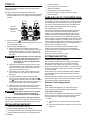
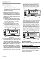
CONTROL OPERATION & LAYOUT
Large LED Display
A large 2 digit LED readout is highly visible in most
installations.
Simplied Three-Step Programming
Only three buttons are required to fully program the control.
Camshaft Indicator
A column of windows located on the left of the control provides
a visual indicator of the camshaft rotation.
Manual Regen Button
The Manual Regen button when pressed initiates either a
delayed regeneration or immediate regeneration.
Time Button
When pressed will display the current hour of day for 5
seconds. Press again quickly to change the hour of day by 1.
Press and hold to change rapidly.
Salt Button
Press to display the current setting (HE/HC) for 5 seconds.
Press again during the 5 seconds to change the setting.
Hardness Button
Press to display the hardness setting for 5 seconds. Press
again during the 5 seconds to change the setting by 1 grain per
gallon. Press and hold to change rapidly.
Flow Indicator
The decimal point/ow indicator blinks on and off when water
ow turns the meter.
Power Loss Memory Retention
The control features battery-free Time of Day retention during
loss of power. The Time will remain in memory.
NOTE: All other programmed parameters are stored in
the ash memory and are retained during power
outages. Flash memory retention is 100 years
Refill
Control Cap
Injector
Cap
Camshaft
Indicator
Regen
Button
Display
Time
Button
Salt
Button
Hardness
Button
Remove
Cover
Figure 11
OM26K • 9

PROGRAMMING
Plug in the control. Un-programmed controls will have the
following settings.
Default settings:
• Hardness - 25 grains per gallon
• Salt setting - HC, High capacity
• System will recharge every 7 days (calendar override)
even if no water is used. Unplug system for long
periods of no water usage. Calendar override is not
programmable.
To change settings
1. Set hour of day - The controller starts (defaults) with 0
hours as the time. To change the hour of the day press
until the desired hour appears in the display. Minutes will
not be shown. Any elapsed minutes after the displayed hour
will be reset to zero when the hours is changed. The range
of hours is 0-23.
A. Time of recharge - The softener will recharge when the
controller reaches 2:00 AM (02 is displayed). If this time
is acceptable then the controller should be set for the
correct hour of the day. If you want the recharge to start
at some other time then change the clock setting.
B. Recharge sooner - Set the clock ahead by the number
of hours needed. Advancing the hours by two will cause
the recharge to start at midnight.
C. Recharge later - Set the clock back by the number of
hours needed. Backing up the hours by two will cause
the recharge to start at 4:00 AM (04 is displayed).
Figure 12 Step 1
2. Pick the salt setting - If you had your water tested, the
hardness is described as grains per gallon. Use this
number to help select the HC or HE setting. The controller
starts (defaults) with the HC (high capacity) setting. If you
want to check or change the setting, press the Salt Amount
button
to display the current setting. To change it, press
the Salt Amount button again within 5 seconds. The setting
will be saved after 5 seconds.
HC this setting maximizes the system capacity between
recharges and will also use the most salt. This setting can
be used if you have high water hardness (26 grains per
gallon) or high water usage. Example: 3 or more people
and/or more than 26 grains per gallon.
HE this setting minimizes salt used for a recharge (uses
the least amount of salt) and provides the least amount of
water between recharges. This setting can be used if you
have low water hardness (13 grains per gallon) or low water
usage. Example: 2 people or less and/or less than
20 grains per gallon.
Figure 13 Step 2
3. Enter the hardness of the water - The controller starts
(defaults) at a hardness of 25 grains per gallon. Check your
water for the actual hardness. Press the Water Hardness
button
to display the current settings. To change the
setting press the button again within 5 seconds. To rapidly
increase the setting push and hold the Water Hardness
button. Release the button and the setting will be saved
after 5 seconds. A hardness setting too high will cause the
system to recharge more often than needed and use more
salt and water than what is needed to soften your water. A
hardness setting too low will cause the system to recharge
less often. The system may pass hard water shortly before
it recharges.
Figure 14 Step 3
Programming is complete.
NOTE: During programming if a button is not pushed
for 5 seconds, the control returns to the normal
operation mode and displays the hour of day.
AUTOMATIC RECHARGE
The OM26K uses an internal water meter that counts the
gallons used. When the recharge setpoint (gallons of water
treated) is reached, the unit will recharge. The setpoint
depends on the capacity setting used (HE or HC) and the
hardness of the water. See page 19 for rated capacities and
system performance.
10 • OM26K

MANUAL REGENERATION
Delayed Regeneration
Press and release
to program a delayed regeneration. The
system will regenerate at the next Time of Regeneration
(2:00 AM). Repeat procedure to disable the Delayed Regen.
Regen dot blinks when delayed regeneration is on.
Immediate Regeneration
Press and hold the
for 3 seconds to initiate an immediate
regeneration. The control cycles to backwash. The control
will proceed through a complete regeneration. A cascading
symbol (- -) will be displayed until regeneration is complete.
The symbol (- -) is not displayed during a quick cycling of the
control.
Figure 15
QUICK CYCLING THE CONTROL
Quick Cycling
Press and hold the
for 3 seconds to initiate an immediate
regeneration. The control will cycle to the backwash cycle.
1. Press and release the
to display "C 1"
2. Simultaneously press then release
and to move the
control to the next cycle.
NOTE: The time may be displayed for 5 seconds.
3. Press and release the
to display "- -" or the "C#".
Continued pressing of
will switch the display between
"- -" and "C#".
4. Repeat steps 2 and 3 to cycle through each position.
Quick Cycle to Service Position
Simultaneously press
and and hold for 3 seconds during
any regeneration cycle. The control will skip the remaining
regeneration cycles and return to the service position. The
Time of Day will be displayed when the control reaches the
service position.
Figure 16
CYCLE DEFAULTS TABLE
Recharge Cycles:
Table 1 Length of Cycle Time remaining to
end of cycle
Cycle Cycle
Description
HE
Setting
HC
Setting
HE
Setting
HC
Setting
1 Backwash 1 10 min 10 min 76.6 min 105.6
min
2 Brine Draw
55 min 74 min 66.6 min 95.6 min
Slow Rinse
3 Re-
Pressurize
3 min 3 min 11.6 min 21.6 min
4 Fast Rinse 1 4 min 4 min 8.6 min 18.6 min
5 Backwash 2 1 min 1 min 4.6 min 14.6 min
6 Fast Rinse 2 1 min 1 min 3.6 min 13.6 min
7 Rell 2.6 min 12.6 min 2.6 min 12.6 min
*The camshaft does not move between Brine Draw and Slow Rinse.
Slow Rinse begins when the brine in the salt tank runs out and the
check valve closes.
Recharge Cycle Requirements:
Minimum Salt/
Capacity
HE
Maximum Salt/
Capacity
HC
Salt/Recharge
(lbs)
2.6 12.8
Recharge Time
(min)
75 109
Water to Drain
(gal)
37 44
Max. Flow to Drain
(gpm)
1.7 1.7
OM26K • 11

START-UP
The conditioner will now need to be placed into operation.
Please review Quick Cycling the Control procedure before
attempting start-up.
DO NOT put regenerant material into the brine tank.
1. With the supply water for the system still turned off, position
the bypass valve to the “not in bypass” (normal operation)
position.
Both valve
handles pointing
in direction of
water flow
2. Press and hold the button on the controller for 3
seconds. This will initiate a manual regeneration, and cycle
to the backwash position.
3. Filling the media tank with water.
A. With the conditioner in backwash, open the water
supply valve very slowly to approximately the 1/4 open
position. Water will begin to enter the media tank. Air
will begin to be purged to drain as the media tank lls
with water.
WARNING:
If opened too rapidly or too far, media may
be lost out of the tank into the valve or the
plumbing. In the 1/4 open position, you
should hear air slowly escaping from the
valve drain line.
B. When all of the air has been purged from the media
tank (water begins to ow steadily from the drain line),
open the main supply valve all of the way. This will
purge the nal air from the tank.
C. Allow water to run to drain until the water runs clear
from the drain line. This purges any debris from the
media bed.
D. Pour about 3 gallons of water into the brine tank.
Advance to cycle 2 (Brine Draw) by pressing the
and
buttons at the same time. The water in the brine
tank should be drawn into the valve. If the water is not
receding from the tank, refer to Troubleshooting.
E. Quickly cycle the control to the rell cycle (C7). Place
salt in brine tank. Allow this cycle to nish and the
control to move to service. The brine tank will have the
correct amount of water.
WARNING:
Ensure that the system has been properly
disinfected per the water conditioning
system manufacturer's recommendations.
The water conditioning system is now fully operational.
The display will show the hour of the day. The decimal point at
bottom center of the display will blink when water is owing.
INSTALLATION CHECKLIST
___ Read the owner's/installation manual?
___ Follow all safety guidelines in the manual?
___ If metal pipe was used, did you restore the electrical ground?
___ Securely install both drain hoses to an approved drain?
___ Perform a leak test?
___ Move the bypass valve to service?
___ Sanitize the softener?
___ Add salt pellets to the salt storage tank?
___ Program the control correctly to meet your needs?
___ Start a recharge?
CARE AND USE OF YOUR BRINE TANK
Each time the softener recharges, salty water (brine) is needed
to recondition the media in the water tank. The brine is pulled
from the salt tank at a controlled amount. If the salt tank does
not contain enough salt, the brine is weak, the media will not
fully recondition and untreated water will pass through.
You must keep salt in the tank.
The salt tank operates best when the salt level is below half-
full. If the tank is lled more than that the salt pellets may
"bridge". The salt pellets wedge against each other and do
not fall into the water at the bottom. Bridging will eventually
provide no salt to make brine. The softener will recharge but
not recondition the media. A salt bridge can be broken up using
a broom handle or similar rod. Carefully pound it into the salt
and the pellets will collapse. After loosening the salt pellets wait
2 hours and start a regeneration. A second recharge may be
needed to fully recondition the media.
You should only use sodium chloride pellet salt for water
softeners. Other types of salt (rock or snow melting) will
contain dirt and chemicals that will affect your water softener.
Keep the brine tank covered.
Empty and clean the tank every 3 years.
SYSTEM DISINFECTION
Disinfection Of Water Softeners
The materials of construction of the modern water softener
will not support bacterial growth, nor will these materials
contaminate a water supply. During normal use, a softener
may become fouled with organic matter, or in some cases with
bacteria from the water supply. This may result in an off-taste
or odor in the water.
Some softeners may need to be disinfected after installation
and some softeners will require periodic disinfection during
their normal life.
Depending upon the conditions of use, the style of softener, the
type of ion exchanger, and the disinfectant available, a choice
can be made among the following methods.
Sodium or Calcium Hypochlorite
Application
These materials are satisfactory for use with polystyrene
resins, synthetic gel zeolite, greensand and bentonites.
5.25% Sodium Hypochlorite
These solutions are available under trade names of household
bleach. If stronger solutions are used, such as those sold for
commercial laundries, adjust the dosage accordingly.
1. Dosage
A. Polystyrene resin; 1.2 uid ounce (35.5 ml) per cubic
foot.
B. Non-resinous exchangers; 0.8 uid ounce (23.7 ml) per
cubic foot.
12 • OM26K

SYSTEM DISINFECTION continued
2. Salt tank softeners
A. Backwash the softener and add the required amount of
hypochlorite solution to the well of the salt tank. The salt
tank should have water in it to permit the solution to be
carried into the softener.
B. Proceed with the normal recharge.
Calcium Hypochlorite
Calcium hypochlorite, 70% available chlorine, is available
in several forms including tablets and granules. These solid
materials may be used directly without dissolving before use.
1. Dosage
A. Two grains (approximately 0.1 ounce [3 ml]) per cubic
foot.
2. Salt tank softeners
A. Backwash the softener and add the required amount
of hypochlorite to the well of the salt tank. The salt tank
should have water in it to permit the chlorine solution to
be carried into the softener.
B. Proceed with the normal recharge.
ACCESSING HISTORY VALUES
The control features a review level that displays the operation
history of the system. This is a great troubleshooting tool for
the control valve.
To access history values, press Recharge
followed by the
Salt Amount button
and hold for 3 seconds to view the
Diagnostic Codes.
NOTE: If a button is not pushed for 30 seconds the
controller will exit the history table.
Press the Time of Day button
to increment through the
table. When the desired code is reached, Press the Salt
Amount button
to display the value.
Some of the values have four digits 1, 2, 3, 4. Press the Salt
Amount button
to display the rst two (1, 2). Press the
Water Hardness button
to display the last two (3, 4).
When the Salt Amount button
is pressed to view H2 the
current ow rate will be displayed but not updated. Continue to
press and release the Salt Amount button
every 5 seconds
to update the display. The ow dot on the display will ash
when there is ow thru the softener.
Code Description Notes
H1 Days since last recharge Days since last recharge
H2 Current ow rate Gallons per minute
H3 Current day of week Current day of week
H4 Water used today since 0200
In gallons,
max value displayed 9999
max value stored 65,535.
H5 Water used since last recharge
A0 Average water usage for day 0
A1 Average water usage for day 1
A2 Average water usage for day 2
A3 Average water usage for day 3
A4 Average water usage for day 4
A5 Average water usage for day 5
A6 Average water usage for day 6
Item No. QTY Part No. Description
1 ........... 1 .......4001927......... Resin Tank Assy, 8 x 44,
OM26K
A.......................................... Resin Tank, 8 x 44
B ......................................... Lower Distributor Assembly
8 x 44 Tank
C ......................................... Upper Basket
D ......................................... Conditioning Resin
TANK ASSEMBLY
D
A
C
B
1
OM26K • 13

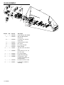
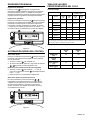
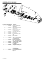
Item No. QTY Part No. Description
1 ........... 1 .......4001925......... Valve Assembly, 368, OM26K
A...................4001260......... 368 Valve Motor/Optical
Sensor Assy
B ..................3025328......... “G” Injector, Tan, w/screen
8 Inch Tank
C ..................3027837......... Assembly, Sensor Cable
D ..................4001926......... 607 Control
E ..................4001889......... Kit, O-ring, 360 Valve
F ...................3027839......... Meter Assembly
2 ........... 1 .......1000811 ......... 120 VAC, 60 Hz, N. America
Plug
3 ........... 1 .......4000996......... Fitting, Drain Line, 90°, 1/2"
NPT, 1/2" Tube
4 ........... 1 .......3031825......... Kit, O-ring, Manifold
5 ........... 1 .......4000886......... Bypass Valve Assembly
6 ........... 1 .......4000888......... Connector Kit, 1" NPT
(Includes Clip Retainer and
Connector Assy)
7 ........... 1 .......4001028......... Kit, Drain Line Flow Control
8 ........... 1 .......4000871......... Female Elbow, 3/8 NPT to
3/8 Tubing
VALVE ASSEMBLY
5
8
3
7
1
4
F
2
B
A
D
C
6
E
14 • OM26K

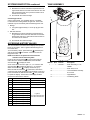
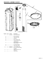
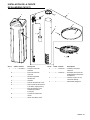
BRINE WELL ASSEMBLY CH15675
Item No. QTY Part No. Description
1 ........... 1 .......CH15675 ....... Brine Well Assembly
A.......................................... Brine Well w/Slots
B ......................................... Safety Brine Valve
C ......................................... Grommet
D ......................................... Brine Tube 3/8" x 60"
E ......................................... Cap, Brine Well 4" Dia.
(Caplug STP-4)
F .......................................... Brine Float w/One Grommet
(As purchased)
G ......................................... Air Check Assembly
H ......................................... Tubing Insert, Brass
2 ........... 1 .......CH34413 ....... Cover and Brine Tank
3 ........... 1 .......CH20774 ....... Brine Tank Overow Fitting
Assembly
4 ........... 1 .............................. Tubing, 12 Foot, 1/2" ID,
Drain Line
5 ........... 1 .............................. Clamp, Hose
4
A
E
5
1
3
2
G
F
H
D
C
B
H
OM26K • 15

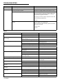
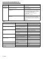
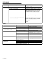
TROUBLESHOOTING
706 Control - Error Codes
Problem Possible Cause Solution
Err 1 is displayed. Program settings have been corrupted. Press any key. If Err 1 does not clear, replace control.
Err 3 is displayed. Control does not detect the camshaft position and is
returning to the service position.
Wait until the control returns to the service position. Flashing
hourglass in the display indicates that the motor is running
Camshaft is not turning during Err 3 display. Check that motor is connected. Verify that the motor wire
harness is connected to motor and controller module. Verify
that optical sensor is connected and in place. Verify that
motor gear has engaged the camshaft.
If everything is connected, replace components in this order:
1. Motor Assembly, Optical Sensor
2. Control
Camshaft is turning more than ve minutes to nd Home
position:
Verify that optical sensor is in place and connected to wire.
Inspect for debris in the camshaft slots.
If motor continues to rotate indenitely, replace the following
components in this order:
1. Optical Sensor
2. Control
System
Problem Possible Cause Solution
Salt tank overow. Loose salt line connection. Ensure all salt line connections are tight.
Drain line restricted with debris. Clean drain control.
Flowing or dripping water at drain or salt line
after recharge.
Debris is preventing #4 valve disc from
closing. See Figure 17.
Remove debris.
Worn #4 valve disc. See Figure 17. Replace valve discs.
Hard water leakage after recharge. Improper recharge. Repeat recharge after making certain correct
salt dosage was set.
Leaking of external bypass valve. Replace bypass valve.
O-Ring around riser pipe damaged. Replace O-ring.
Control will not draw salt. Restricted drain line. Remove restriction.
Injector plugged. Clean injector and screen.
Debris is preventing valve discs from closing.
See Figure 17.
Remove foreign matter from valve discs.
Control will not recharge automatically. AC adapter or motor not connected. Connect power.
Defective motor. Replace motor.
Meter clogged with debris. Unit will recharge
every 7 days anyway.
Remove and clean meter.
Control recharges at wrong time of day. Time of Day set incorrectly. Set the correct Time of Day.
Intermittent salt draw. Low water pressure. Maintain a minimum of 20 psi
(1.3 bar) feed.
No conditioned water after recharge. No salt in salt tank. Add salt to salt tank.
Injector plugged. Clean injector and screen.
Backwashes or purges at excessively low or
high rate.
No drain line ow control. Install drain line ow control.
Restricted drain line. Remove restriction.
Runs out of conditioned water between
recharges.
Control improperly programmed. Verify salt dosage.
Flow indicator on control does not display
service ow.
Bypass valve in bypass position. Remove bypass valve from bypass.
Meter cable dislodged from valve. Fully insert meter cable into valve.
Meter clogged with debris. Remove and clean meter.
Water hammer Air in media tank. Check all salt line connections for air leaks.
Tighten to stop air leaks.
Air check not sealing. Clean air check assembly.
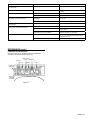
16 • OM26K

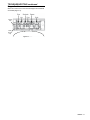
Flapper Positions
When the control cover is removed the appers and camshaft
are visable (Figure 17).
Injector
Cap
Refill
Control
Cap
Figure 17
TROUBLESHOOTING continued
OM26K • 17

PENTAIR RESIDENTIAL FILTRATION, LLC LIMITED WARRANTY
Water Softener
Pentair Residential Filtration, LLC (hereinafter “PRF”) warrants to the original owner, that under normal use: Fiberglass mineral
tanks and brine tanks for water softeners will be free from material defects in materials and workmanship for ten (10) years from
the date of purchase. The control valve electronic controller, valve bodies and internal valve parts (not including brine injectors)
for water softeners will be free from material defects in materials and workmanship for ve (5) years from the date of purchase.
Additional parts for water softeners not mentioned above will be free from material defects in materials and workmanship for
two (2) years from the date of purchase. Any replacement products furnished will be free from material defects in materials and
workmanship for the remainder of the original warranty period.
This warranty does not cover: (1) water softening resin (2) damage due to lightning or other conditions beyond the control of PRF
(3) defects not reported within the above-stated time periods, (4) items manufactured by other companies, (5) problems arising
from failure to comply with PRF instructions, (6) problems or damage arising from acts of nature, abuse, misuse, negligence
or accident (7) problems or damage resulting in whole or in part from alteration, modication, repair or attempted alteration,
modication or repair by any party other than PRF or a PRF authorized dealer (8) noncompliance with applicable codes/
ordinances.
If a defect in workmanship or materials in a product or part covered by the warranty should arise, PRF at its sole discretion, will
repair or replace the defective product or part.
All claimed defective product or parts must: (1) be authorized for return by PRF with a Return Goods Authorization number (2)
include proof of the purchase date of the product or part (3) be returned to PRF prior to the expiration of the applicable warranty
period, at the customer's expense, shipment pre-paid, (4) be accompanied by a letter detailing the Model Number, Serial Number
(if any), and a brief description of the problem.
TO THE MAXIMUM EXTENT PERMITTED BY APPLICABLE LAW, PRF DISCLAIMS ALL OTHER WARRANTIES, WHETHER
EXPRESS OR IMPLIED, INCLUDING, BUT NOT LIMITED TO, THE IMPLIED WARRANTIES OF MERCHANTABILITY AND
FITNESS FOR A PARTICULAR PURPOSE, WITH REGARD TO THE PRODUCTS, PARTS AND ANY ACCOMPANYING
WRITTEN MATERIALS.
To the maximum extent permitted by applicable law, PRF shall not be liable for any damages whatsoever (including, but not limited
to, loss of time, inconvenience, expenses, labor or material charges incurred in connection with the removal or replacement of
the product or part, special, incidental, consequential, or indirect damages for personal injury, loss of business prots, business
interruption, loss of business information, or any other pecuniary loss) arising out of the use of or inability to use the defective
products or parts, even if PRF has been advised of the possibility of such damages.
PRF’s maximum liability under any provision of this Limited Warranty shall be limited to the amount actually paid for the product or
part.
NOTE: Because some states do not allow the exclusion or limitation of incidental or consequential damages, the above
limitations or exclusions may not apply.
THIS WARRANTY GRANTS SPECIFIC LEGAL RIGHTS, AND OTHER RIGHTS MAY APPLY. SUCH RIGHTS VARY FROM
STATE TO STATE.
7-2010
18 • OM26K

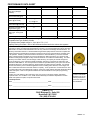
PERFORMANCE DATA SHEET
Model OM26K
Maximum Rated Service
Flow (gpm) (W/upper
collector)
8
Pressure Drop at Rated
Service Flow Rate (gpm)
14
Rated Capacity
(grains @ lbs of salt)
11,902 @ 2.7
27,149 @ 13.1
Rated Efciency
(grains/lb Salt @ lb of salt)
4,400 @ 2.7 lbs
Maximum Flow Rate During
Regeneration (gpm)
1.7
Resin Volume per tank - ft
3
Resin Type - Strong Acid
Cation
0.82 ft
3
per tank
Tank size 8" x 44"
Operating Pressure:20 -125 psi or 1.4 – 8.8 kg/Centimeter
2
, Operating Temperature: 34 - 110° F or 1.1 – 43.3° C
Acceptable Salt Type: Sodium Chloride
All Systems above tested at 35psi +/- 5 psi, pH of 7.5 +/- 0.5,
Capacity Testing Flow Rate = 50% of the rated service ow rate for the various size systems.
These water softener systems have been tested by WQA and conform to NSF/ANSI 44 for specic
performance claims as veried and substantiated by test data. The rated salt efciencies above were also
determined in accordance with NSF/ANSI 44 and are only valid at the salt dosage referenced above. An
efciency rated water softener is a demand initiated regeneration (DIR) softener which also complies with
specic performance specications intended to minimize the amount of regenerant brine and water used
in its operation. Efciency rated water softeners shall have a rated salt efciency of not less that 3350
grains of total hardness exchanged per pound of salt (based on NaCl equivalency) (477 grams of total
hardness exchanged per kilogram of salt), and shall not deliver more salt than its listed rating. The rated
efciency of the water softener, the salt dosage at that efciency, the capacity at that salt dosage and
that of the efciency is only valid at the stated salt dosage. Efciency is measured by a laboratory test
described in NSF/ANSI 44. The test represents the maximum possible efciency the system can achieve.
Operational efciency is the actual efciency achieved after the system has been installed. It is typically
less than the efciency due to individual application factors including water hardness, water usage, and
other contaminants that reduce the water softener’s capacity. These systems are not intended to be used
for treating water that is microbiologically unsafe or of unknown quality without adequate disinfection before
or after the system. Refer to the system Installation and Service Manals for set-up and programming
instructions.
Contact your local dealer for parts and service. See your owner’s manual for warranty information.
Important Notice: For conditions of use, health claims certied by the California Department of Public
Health and replacement parts, see product data sheet
Iowa Requirement:
Seller: ________________________________________________ Date: _________________________
Buyer: ________________________________________________ Date: _________________________
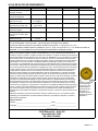
Tested and Certied
by WQA to NSF/ANSI
Standard 44 & 372 for
softener performance
& lead free compliance
and CSA B483.1.
OMNIFILTER
13845 Bishops Dr., Suite 200
Brookeld, WI 53005
PH: (800) 279-9404
OM26K • 19
Page is loading ...
Page is loading ...
Page is loading ...
Page is loading ...
Page is loading ...
Page is loading ...
Page is loading ...
Page is loading ...
Page is loading ...
Page is loading ...
Page is loading ...
Page is loading ...
Page is loading ...
Page is loading ...
Page is loading ...
Page is loading ...
Page is loading ...
Page is loading ...
Page is loading ...
Page is loading ...
Page is loading ...
Page is loading ...
Page is loading ...
Page is loading ...
Page is loading ...
Page is loading ...
Page is loading ...
Page is loading ...
Page is loading ...
Page is loading ...
Page is loading ...
Page is loading ...
Page is loading ...
Page is loading ...
Page is loading ...
Page is loading ...

©2018 Pentair Residential Filtration, LLC. All rights reserved. 4000984 Rev H AP19
OMNIFILTER
§
Brookfield, WI 53005 800.279.9404 www.omnifilter.com
§
For a detailed list of where Pentair trademarks are registered,
please visit waterpurication.pentair.com/brands. Pentair
trademarks and logos are owned by Pentair plc or its afliates.
Third party registered and unregistered trademarks and logos
are the property of their respective owners
.
§
Para obtener una lista detallada dónde están registradas las
marcas comerciales de Pentair, sírvase visitar
waterpurication.pentair.com/brands. Las marcas comerciales y
logotipos de Pentair son propiedad de Pentair plc o sus liales.
Las marcas comerciales y logotipos registrados y sin registrar de
terceros son propiedad de sus respectivos propietarios.
§
Pour une liste détaillée des sites de dépôt des marques
commerciales Pentair, veuillez visiter
waterpurication.pentair.com/brands. Les marques commerciales
et les logos Pentair sont la propriété de Pentair plc ou de ses
liales. Les marques commerciales et déposées et les logos tiers
sont la propriété de leurs détenteurs respectifs
.
-
 1
1
-
 2
2
-
 3
3
-
 4
4
-
 5
5
-
 6
6
-
 7
7
-
 8
8
-
 9
9
-
 10
10
-
 11
11
-
 12
12
-
 13
13
-
 14
14
-
 15
15
-
 16
16
-
 17
17
-
 18
18
-
 19
19
-
 20
20
-
 21
21
-
 22
22
-
 23
23
-
 24
24
-
 25
25
-
 26
26
-
 27
27
-
 28
28
-
 29
29
-
 30
30
-
 31
31
-
 32
32
-
 33
33
-
 34
34
-
 35
35
-
 36
36
-
 37
37
-
 38
38
-
 39
39
-
 40
40
-
 41
41
-
 42
42
-
 43
43
-
 44
44
-
 45
45
-
 46
46
-
 47
47
-
 48
48
-
 49
49
-
 50
50
-
 51
51
-
 52
52
-
 53
53
-
 54
54
-
 55
55
-
 56
56


Pentair OMNIFILTER OM26K Owner's manual
- Type
- Owner's manual
- This manual is also suitable for
Ask a question and I''ll find the answer in the document
Finding information in a document is now easier with AI
in other languages
Related papers
-
Pentair Pro Elite 268-762-100-1044 Demand Owner's manual
-
-
Autotrol 255 & 400 Series Owner's manual
-
Pentair 5600SXT User manual
-
-
OmniFilter RV1 Owner's manual
-
-
-
-
Autotrol AUTOTROL 760 CONTROL 255 Owner's manual
Other documents
-
-
GE Pro Elite 268-716-150-1248 Operating instructions
-
Culligan HE Series Owner's manual
-
EcoWater 7283560 Owner's manual
-
Whirlpool WHES33 Specification
-
North Star NSC15ED Installation Operation & Maintenance
-
-
-
-