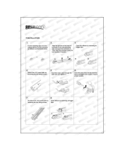
Martin Alien 02 Spot User manual

Category
Cool boxes
Type
User manual

This manual is also suitable for

Alien 02
user manual
martinarchitectural
Measurements are in millimeters
310
134
195
ø235
800
300
* Alien 02 Pendant shown. Lamp measurements also apply to Alien 02 Spot
© 2002-2005 Martin Professional A/S, Denmark.
All rights reserved. No part of this manual may be reproduced, in any form or by any means, with-
out permission in writing from Martin Professional A/S, Denmark.
Printed in Denmark.
P/N 35000111, Rev G
Introduction............................................................ 4
Safety information ......................................................................4
Installation ............................................................. 6
Unpacking .................................................................................6
Fixture orientation and location .....................................................6
Power and data connection..........................................................7
Mounting an Alien 02 Pendant .....................................................8
Mounting an Alien 02 Spot ........................................................12
Accessories.......................................................... 14
Lens options............................................................................14
Glare control kit .......................................................................15
Barn door kit ...........................................................................16
Service ................................................................ 17
Lamp replacement ...................................................................17
Optimizing lamp alignment .........................................................19
Cleaning..................................................................................20
Specifications - Alien 02 Pendant ............................ 21
Specifications - Alien 02 Spot ................................. 32
4Introduction
Introduction
1
Thank you for selecting the Martin Alien 02. The Alien 02 is an automated
150-watt color-changing medium-throw light designed for fixed interior
installation. It features seamless CMY color mixing and full-range
continuous dimming. The fixture may be operated with DMX control
devices.
This manual describes installation, accessories and servicing for the Alien
02 Spot and the Alien 02 Pendant models. For information on operating and
controlling these luminaires refer to the 150W Base user manual.
The Alien 02 product range is made up of a number of luminaires and
accessories:
Alien 02 Spot - a pedestal or arm mounted luminaire
Alien 02 Pendant - a ceiling hung luminaire
150W Base - provides power and intelligent control functions to one or two
Alien 02 luminaires (Single or Double models)
Mounting arm for the Alien 02 Spot
J-Box for mounting the Alien 02 Pendant
Cable extension kits for extending the distance between an Alien 02
luminaire and a 150W Base.
36° fresnel lens kit
90° x 70° beam shaper lens kit
Micro lens diffuser kit
Barn doors
Glare control kit
Safety information
Warning! This product is for professional use only. It is not for household
use.
This product presents risks of lethal or severe injury due to fire and heat,
electric shock, ultraviolet radiation, lamp explosion, and falls. Read this
manual before powering or installing the fixture, follow the safety
precautions listed below and observe all warnings in this manual and on the
fixture. If you have questions about how to operate the fixture safely, please
Introduction 5
contact your Martin dealer or call the Martin 24-hour service hotline at +45
70 200 201.
Protection from electric shock
Disconnect the fixture from AC power before removing or installing the
lamp, fuses, or any part, and when not in use.
Always ground (earth) the fixture electrically.
Use only a source of AC power that complies with local building and
electrical codes and has both overload and ground-fault protection.
Do not expose the fixture to rain or moisture.
Refer all service to a Martin service technician.
Protection from UV radiation and lamp explosion
Never operate the fixture with missing or damaged lenses and/or covers.
When replacing the lamp, allow the fixture to cool for at least 5 minutes
before opening the fixture or removing the lamp. Protect your hands and
eyes with gloves and safety glasses.
Do not stare directly into the light. Never look at an exposed lamp while it is
lit.
Replace the lamp if it becomes defective or worn out.
Protection from burns and fire
Never attempt to bypass the thermostatic switch or fuses. Always replace
defective fuses with ones of the specified type and rating.
Keep all combustible materials (for example fabric, wood, paper) at least 1
meters (39 inches) away from the Alien 02 luminaire.
Do not illuminate surfaces within 0.5 meters (20 inches) of the fixture.
Provide a minimum clearance of 0.1 meters (4 inches) around fans and air
vents.
Never place filters or other materials over the lens.
The exterior of the fixture can reach temperatures up to 55° C (194° F) at
room temperature (25° C / 77° F). Allow the fixture to cool before handling.
Do not modify the fixture or install other than genuine Martin parts.
Do not operate the fixture if the ambient temperature (Ta) exceeds 40° C
(104° F).
Protection from injury due to falls
When suspending the fixture above ground level, verify that the structure
can hold the weight of all installed devices plus a suitable safety margin.
Verify that all external covers and rigging hardware are securely fastened
Block access below the work area whenever installing or removing the
fixture.
6 Installation
Installation 2
This section describes in general terms how to mount the fixture and
connect it to data and power. These procedures must be performed by
qualified professionals. The installer must make sure that the installation
conforms to all local safety regulations and legal requirements.
Note that all measurements in diagrams are expressed in millimeters (mm).
Unpacking
The Alien 02 comes with the following items:
Philips CDM-SA/T 150 W discharge lamp (installed)
User manual
Alien 02 Pendant luminaires are also supplied with a 3 mm Allen wrench
(clipped to the fixture near the cables).
Fixture orientation and location
Note: The built-in cables that connect the Alien 02 to a 150W Base are
less than 1 metre long. If the distance between the two fixtures
is to be greater you can order a cable extension kit to extend
the distance up to a total of 16 metres. Keep these relative
distances in mind when positioning your fixtures.
Do not locate the Alien 02 luminaire in an unventilated space. Install the
fixture in a location where it is:
at least 0.5 meters (20 inches) away from the surface to be illuminated,
at least 1 meter (40 inches) away from any combustible materials, and
away from accidental public contact.
Installation 7
Power and data connection
Power and data connection can be performed before or after mounting the
luminaire. We recommend that you familiarize your self with this section,
and perform as much of the work in advance of mounting the luminaire as is
practical.
The Alien 02 luminaire receives its power and data from a 150W Base
(Single or Double) and is connected using the attached cables, and if
necessary a Cable Extension Kit.
Warning Do not connect the Alien 02 luminaire directly to mains power
supply - doing so will result in damage to the lamp and the local
power supply.
Powering through a dimmer system can damage the fixture.
1 The power-cable on the Alien 02 luminaire is connected to the DISCHARGE
LAMP OUTPUT socket on the 150W Base.
2 The 26-pin plug on the data cable attached to the Alien 02 luminaire is
connected to the DATA OUT socket on the 150W Base. Screw the
connector into place.
3 Power is supplied to the 150W Base MAINS INPUT socket from the AC
mains distribution system. Do not connect the fixture to a dimmer system.
Mains
80-250V AC
50/60 Hz
DISCHARGE
LAMP
OUTPUT
Alien 02 luminaire
150W Base (Single or Doubl
e
8 Installation
Cable extension kits
Cable extension kits are available that allow the distance between an Alien
02 luminaire and a 150W Base to be extended up to a maximum of 16
meters. The kits contain a power cable extension and a data cable
extension. Kits are available in 2, 5, and 10 metre (6.5, 16, and 33 feet)
extension lengths.
Mounting an Alien 02 Pendant
Prerequisites
The Alien 02 is designed to be hung from a ceiling using the separately
orderable Alien 02 J-Box. This should be installed securely before the Alien
02 is attached.
The 150W Base that supplies power to and controls the luminaire should be
installed and be connected to AC power. The power and data cables should
be connected to the 150W Base and run out to the J-Box in preparation for
connection to the luminaire.
If the luminaire is to be used for upwards projection then some adjustments
should be made before it is mounted. See “Upwards projection” on page 11.
Mounting procedure
1 Remove the J-Box cover by loosing the 3 Allen screws around the rim. You
can use the 3 mm Allen wrench that is supplied with the Alien 02 (you can
find it clipped to the luminaire support near the cables).
Installation 9
2 Using the 3 mm Allen wrench to loose the two locking screws, remove the
slotted section of the J-Box.
3 Pass the cables and mounting flange of the Alien 02 though the center of
the J-Box cover.
4 Slide the flange into the slot on the J-Box. Replace the slotted section (note
that the dotted circle represents a cutaway of the J-box cover).
10 Installation
5 Move the Alien 02 Pendant to the correct pan position and screw the two
pan locking screws in place using the 3 mm Allen wrench. Loosen the three
Allen screws on the arms of the J-Box.
6 Connect the cables on the Alien 02 to the cables that are connected to the
150W Base. The cables can either be passed into a ceiling space through
the J-Box, or passed through the two holes in the J-Box cover (make a cut in
each of the rubber washers and slip the cables into the hole through these).
7 Push the J-Box cover into place, choosing one of the three possible
positions that best suits your cabling configuration.
8 Using the 3 mm Allen wrench, tighten the three Allen screws that hold the
cover in position.
Installation 11
Adjusting the projection angle
The Alien 02 is shipped in a downwards configuration.
You can adjust the angle of the supporting arms, or the lamp, by making
adjustments at the joints at two positions. To adjust a joint, use the 3 mm
Allen wrench supplied with the fixture to loosen the joints on either side of
the fixture. Adjust to the desired angle - +/- 50 degrees - and re-tighten.
Upwards projection
The luminaire can be configured to project upwards:
50°50°
50°50°
50°50°
50°50°
12 Installation
1 Using the 3 mm Allen wrench supplied with the luminaire, remove the Allen
screws and covers from the joints on each side of the lamp housing.
2 Remove the lamp from the two supporting struts, invert it, and place it back
into the strut mounts.
3 Replace the joint covers and Allen screws.
4 Adjust the projection angle and tighten the Allen screw at the joints.
Mounting an Alien 02 Spot
Pre-requisites
The Alien 02 Spot is attached to a separately orderable Alien 02 Mounting
Arm.
To attach the Mounting Arm to:
Installation 13
The Alien 02 Spot luminaire you need 4 mm and 5 mm hex wrenches.
A surface you need 3 units of M6 mounting hardware appropriate to the
mounting surface and the weight of the future, and associated tools to install
the hardware.
Mounting procedure
Note that these steps need not necessarily be performed in this order. You
may find it easier to attach the mounting arm to the mounting surface before
attaching the Alien 02 Spot luminaire.
1 Attach the Alien 02 Spot to the mounting arm using the supplied hardware
and 4 mm and 5 mm hex wrenches. Do not over tighten the 4 mm locking
bolt until the fixture is installed and pointing in the appropriate direction.
2 Attach the base of the arm to the required surface using M6 mounting
hardware that is appropriate to the mounting surface and to the weight of
the fixture.
3 Adjust the vertical and horizontal angles of the spot so that it is pointing in
the correct direction. Tighten the 4 mm locking screws on the top of the arm
(see the first illustration above) and on the base.
4
5
Ø85
Ø10.5
Ø6.5
13
4
14 Accessories
Accessories
3
This chapter describes the lens options that are available for the Alien 02,
as well as the Glare Control Kit (see page 15) and the Barn Door Kit (see
page 16).
Lens options
The following lenses are available for the Alien 02 luminaire:
70° diffuser lens: The 70° diffuser lens is standard. It provides a symmetric
70° field. It installs with the rough side out, away from the lamp.
36° Fresnel lens: The optional Fresnel lens provides a symmetric 36° field.
It installs with the ridges out, away from the lamp.
90° x 70° beam shaper lens: The optional beam shaper provides an
asymmetric 90° by 70° field. It installs with the ridges facing out, and may be
turned as desired; the ridges are parallel with the short axis of the field. This
lens is lighter and more fragile than the others: be extra careful when
installing the beam shaper lens and tighten the rubber washers just enough
to exert light pressure.
Micro lens diffuser: The Micro lens diffuser provides a very flat field and
improved efficiency compared to the standard optical configuration. It can
be used in short throw applications where exact evenness is required. The
estimated spread angle is 60 degrees.
Changing the lens
Lens installation requires 2.5 and 3 mm Allen
wrenches.
1 Remove the front by unscrewing the three 3 mm
Allen screws. The screws should not be
completely removed as this will damage the
push-on fasteners that hold them in place.
2 Remove the lens bracket and the existing lens.
3 Remove the air filter behind the bracket.
Accessories 15
4 Using a 2.5 mm Allen wrench, remove the three screws and metal plates
that hold the lens in place at the rear of the lens bracket.
5 Remove the lens.
6 Place the new lens flat against the lens bracket with the rougher side in or
out (as described in the previous section). Replace the metal plates and
screws that hold the lens in place.
7 Replace the air filter.
8 Reattach the lens bracket to the fixture.
Glare control kit
The Glare Control Kit consists of a
rotatable grill that is designed to reduce
light leakage.
Requirements
Installing the Glare Control kit requires a 3
mm Allen wrench.
Installation
To install the Glare Control Kit:
1 Remove the three 3 mm Allen screws (and their push-on fasteners) holding
the front lens bracket in place.
2 Place the Glare Control grill over the lens.
3 Screw the grill into place using the longer Allen screws and plates supplied
with the kit.
16 Accessories
Barn door kit
A optional barn door kit can be
ordered for the Alien 02 luminaire.
The barn door kit is easily attached
to the Alien 02 and allows for
precise beam control. The barn
doors can be opened, closed, and
rotated. They can be used in
situations where you need to
shape the bean or prevent light
leakage.
Installation
Installing the barn door kit requires a 3 mm Allen wrench.
To install the barn door kit:
1 Remove the three 3 mm Allen screws (and their push-on fasteners) holding
the front lens bracket in place.
2 Place the barn door kit over the lens.
3 Screw the barn doors into place using the longer Allen screws and plates
supplied with the kit.
Service 17
Service
4
This section describes service procedures that can be performed by the
user. Refer all service not described here to a qualified Martin technician.
Warning! Disconnect the fixture from power before removing any cover.
Lamp replacement
To ensure optimum lamp life:
Turn off lamp power whenever illumination is not required for extended
periods of an hour or more. Fixture power may remain on when not in use.
Always allow the lamp to warm up fully before turning it off.
Avoid turning on several lamps at once.
The Alien 02 can use the following discharge lamps. Installing any other
lamp type may damage the fixture.
Lamp replacement requires 2.5 mm Allen wrench and a Phillips screwdriver.
Warning! Allow the lamp to cool for 15 minutes before removing the lamp
cover.
To replace the lamp:
4 Disconnect the fixture from power and
allow it to cool.
5 Remove the lamp cover at the back of
the fixture using a 2.5 mm Allen
wrench.
Lamp Efficiency Color Temp. Average Life
Philips CDM-SA/T 150W 85 Lm/W 4000 K 6000 hr.
General Electric CMH150 74 Lm/W 4200 K 12000 hours
18 Service
6 Loosen the four screws holding the lamp
holder in place.
7 Gently twist the lamp holder and guide it
out of the housing.
8 Remove the old lamp from the socket.
9 Holding the new lamp by its ceramic base
- do not touch the glass bulb - insert it
firmly and squarely into the lamp socket.
10 Clean the glass bulb with an alcohol wipe
or a clean, lint-free cloth wetted with
alcohol.
11 Gently insert the lamp and screw the
holder into place.
12 Replace the cover and set it in place using
a 2.5 mm Allen wrench.
13 We recommend that you activate the
Lamp Hour Warning function on the 150W
Base and that you set the expected number of hours of life the lamp has.
This is done using the Personality menu on the 150W Base (see the 150W
Base user manual). Remember to also reset the lamp hour counter using
the Information menu on the 150W Base. When the lamp hour counter
reaches:
100 hours less than the expected life time of the lamp, the display on the
150W Base will start blinking LHr in the display. At this point you should
change the lamp to avoid the risk of lamp explosion.
The expected life of the lamp, the lamp shuts off and can not be turned on
again before the counter in the 150W Base is reset, or the predefined lamp
hour warning level has been redefined.
Note: If you are operating two Alien 02 luminaires from a 150W Double
Base then we highly recommend that the lamps be replaced in
both luminaires at the same time. This is so that the Lamp Hour
Warning function has meaning when two lamps are in operation.
Service 19
Optimizing lamp alignment
The lamp alignment is set at the
factory. If, the light distribution is
uneven, lamp alignment may be
adjusted as follows. A 2.5 mm
Allen wrench and a Phillips
screwdriver are required.
14 Disconnect the fixture from AC
power supply and allow the lamp
to cool for 15 minutes.
15 Remove the lamp cover at the
back of the fixture using a 2.5 mm
Allen wrench.
16 The three sprung screws on the
lamp holder are used for lamp
adjustment. Switch on the Alien
02 and allow it to reset.
17 Using either a controller or the
control panel, strike the lamp and
focus the light on a flat surface.
18 Center the hot-spot (the brightest
part of the beam) by turning the 3
adjustment screws. Turn one screw at a time to drag the hot-spot diagonally
across the projected image. If there is no hot-spot, adjust the lamp until the
light is even.
19 To reduce a hot-spot, pull the lamp in by turning all three screws clockwise
1/4-turn at a time until the light is evenly distributed.
20 If the light is brighter around the edge than it is in the center, or if light output
is low, the lamp is too far back in the reflector. “Push” the lamp out by turning
the screws counterclockwise 1/4-turn at a time until the light is bright and
evenly distributed.
21 Replace the lamp cover.
20 Service
Cleaning
Wash the aluminum housing of the Alien 02 with a soft brush or sponge and
a mild, non-abrasive car washing detergent. Rinse.
Cleaning the air filter in the Alien 02 luminaire
Accessing the air filter in an Alien 02 requires a 3 mm Allen wrench.
1 Remove the front lens bracket by
unscrewing the three 3 mm Allen screws.
The screws should not be completely
removed as this will damage the push-on
fasteners that hold them in place.
2 Remove the lens bracket from the fixture.
3 Remove the air filter from behind the
bracket.
4 To clean the air filter, use a vacuum or
compressed air, or soak it in warm soapy
water and blot dry.
5 Replace the air filter.
6 Reattach the lens bracket to the fixture.
  • Page 1 1
  • Page 2 2
  • Page 3 3
  • Page 4 4
  • Page 5 5
  • Page 6 6
  • Page 7 7
  • Page 8 8
  • Page 9 9
  • Page 10 10
  • Page 11 11
  • Page 12 12
  • Page 13 13
  • Page 14 14
  • Page 15 15
  • Page 16 16
  • Page 17 17
  • Page 18 18
  • Page 19 19
  • Page 20 20
  • Page 21 21
  • Page 22 22
  • Page 23 23
  • Page 24 24
  • Page 25 25
  • Page 26 26
  • Page 27 27
  • Page 28 28
  • Page 29 29
  • Page 30 30
  • Page 31 31
  • Page 32 32
  • Page 33 33
  • Page 34 34
  • Page 35 35
  • Page 36 36
  • Page 37 37
  • Page 38 38
  • Page 39 39
  • Page 40 40
  • Page 41 41
  • Page 42 42
  • Page 43 43
  • Page 44 44

Martin Alien 02 Spot User manual

Category
Cool boxes
Type
User manual
This manual is also suitable for

Ask a question and I''ll find the answer in the document

Finding information in a document is now easier with AI