Crestron ST-1700C User manual
- Category
- Mobile device dock stations
- Type
- User manual
This manual is also suitable for

Crestron ST-1700C
1-Way Wireless RF Touchpanel
Operations Guide

This document was prepared and written by the Technical Documentation department at:
Crestron Electronics, Inc.
15 Volvo Drive
Rockleigh, NJ 07647
1-888-CRESTRON
All brand names, product names and trademarks are the property of their respective owners.
©2004 Crestron Electronics, Inc.

Crestron ST-1700C 1-Way Wireless RF Touchpanel
Contents
1-Way Wireless RF Touchpanel: ST-1700C 1
Introduction ...............................................................................................................................1
Functions and Features................................................................................................ 1
Specifications ..............................................................................................................2
Physical Description....................................................................................................3
Industry Compliance ................................................................................................... 5
Setup ..........................................................................................................................................5
Applying Power........................................................................................................... 5
Identity Codes..............................................................................................................6
Configuring the Touchpanel........................................................................................6
General Use and Safety .............................................................................................10
Recommended Touchpanel Cleaning........................................................................10
Programming Software............................................................................................................11
Earliest Version Software Requirements for the PC ................................................. 11
Programming with Crestron SystemBuilder.............................................................. 12
Programming with SIMPL Windows ........................................................................12
Programming with VT Pro-e..................................................................................... 15
Virtual Feedback ....................................................................................................... 15
Optional Pushbuttons.................................................................................................21
Reserved Join Numbers.............................................................................................21
MultiByte International Characters ........................................................................... 22
Uploading and Upgrading........................................................................................................ 23
Communication Settings ...........................................................................................23
Uploading a VT Pro-e Project ...................................................................................27
Firmware Upgrade..................................................................................................... 28
Problem Solving ...................................................................................................................... 30
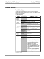
Troubleshooting......................................................................................................... 30
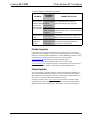
Further Inquiries ........................................................................................................31
Future Updates ..........................................................................................................31
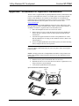
Appendix: Installation of Optional Pushbuttons.....................................................................32
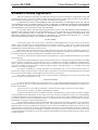
Software License Agreement................................................................................................... 33
Return and Warranty Policies ..................................................................................................35
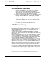
Merchandise Returns / Repair Service ...................................................................... 35
CRESTRON Limited Warranty.................................................................................35
Operations Guide – DOC. 6225A Contents • i


Crestron ST-1700C 1-Way Wireless RF Touchpanel
1-Way Wireless RF Touchpanel:
ST-1700C
Introduction
Functions and Features
The ST-1700C is a one-way wireless RF touchpanel that provides a user interface to
a Crestron
®
control system (herein referred to as the Cresnet
®
system). The
lightweight, hand-held touchpanel, with long-life NiMH battery and RF wireless
communication with a range of up to 300 feet, allows complete freedom of
movement, indoors or out. Customized graphic icons let users easily control any
function.
Included with the ST-1700C are a Crestron High Performance Rechargeable Battery
Pack (ST-BTPN) and a Docking Station (ST-DSN) that docks the touchpanel and/or
recharges the ST-BTPN. An external power pack (PW-1215 for domestic use or
PWI-1215 for international use) is also provided to power the touchpanel. Refer to
the latest revisions of the documentation supplied with these items for descriptions
and details.
The following table provides a functional summary of the ST-1700C.
Functional Summary
• 5.7" (14.48 cm) active color matrix display
• 320 x 240 screen resolution
• 63MIPs ColdFire processor running Crestron Isys
®
generation firmware
• 16-bit non-palette graphics
• 64,000-color Crestron Isys engine
• 4 MB of Flash (3MB reserved for user display lists)
• 8 MB of SDRAM (Synchronous Dynamic RAM) for panel firmware
• Power up on last page
• Long-Life NiMH battery
− fast charging
− no battery memory
• Compatible with existing CNRFGWA RF gateway
• 1-Way RF communication, range up to 300 feet
Operations Guide – DOC. 6225A 1-Way Wireless RF Touchpanel: ST-1700C • 1

1-Way Wireless RF Touchpanel Crestron ST-1700C
NOTE: The ST-1700C is supplied with an optional bezel, two 5-button switch
actuators, and ten black pushbuttons (blank), five for each side of the LCD screen.
You can use these buttons to access any frequently used commands. Refer to
“Appendix: Installation of Optional Pushbuttons” for instructions to install the
optional switches, buttons, and bezel.
NOTE: Two options, 1700C-BTNB (black buttons) or 1700C-BTNS (silver
buttons), can be purchased to provide custom engraved buttons for your touchpanel.
Contact Crestron customer support for more information.
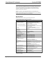
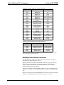
Specifications
Specifications for the ST-1700C are given in the following table.
ST-1700C 1-Way Wireless RF Touchpanel Specifications
SPECIFICATION DETAILS
Power Options
ST-BTPN (or equivalent)
AC: Domestic External Adapter
AC: International External Adapter
ST-DSN
Rechargeable NiMH battery pack (included)
(4100 mAh capacity after full charge. Operating time
depends on usage.)
1
12VDC, 1.5A, 120VAC Input (included)
(P/N PW-1215 or equivalent)
12VDC, 1.5A, 230VAC Input (included with international
version touchpanel)
(P/N PWI-1215 or equivalent)
Docking Station/charger with external power pack
(included)
Default Net ID 3
Default RF ID 10
Default Timeouts 10 minutes for standby
30 minutes for power down
Signal Join Maximums 999 digital
Control System Update Files
2, 3, 4
2-Series Control System
CEN/CN-TVAV
CNMSX-AV/Pro
CNRACKX/-DP
ST-CP
Version C2-2004.CUZ or later
Version 5.10.13V.UPZ or later
Version 5.10.11X.UPZ or later
Version 5.10.11W.UPZ or later
Version 4.02.02S.UPZ or later
Acceptable File Extensions
5
.vtz
.csf
projectname.vtz (compiled file)
ST1700C.vx.xxx.x.csf (panel firmware)
RF Specifications 1-Way Wireless RF Touchpanel, 433.92 MHz, Range
up to 300 feet
6
Memory 4 MByte flash memory (3 Mbytes available for user
programming)
8 MByte SDRAM for firmware storage
EEPROM for NV storage of last page and join #s
Touchscreen Dimensions Height: 3.700 in (9.017 cm)
Width: 4.700 in (11.938 cm)
Touchscreen Resolution 320 x 240 pixels, 64K color ISYS engine
Touchscreen Viewing Angles ±65° for X dir, +65°/-40° for Y dir
Touchscreen LCD Active matrix, 64K colors
Touchscreen Illumination Backlit fluorescent
Touchscreen Composition Resistive Membrane
Operating Temperature 50° to 113°F (10° to 45°C)
(continued on next page)
2 • 1-Way Wireless RF Touchpanel: ST-1700C Operations Guide – DOC. 6225A

Crestron ST-1700C 1-Way Wireless RF Touchpanel
ST-1700C 1-Way Wireless RF Touchpanel Specifications (continued)
SPECIFICATION DETAILS
Humidity 10% to 90% RH (non-condensing)
Overall Dimensions Width: 8.75 in (22.23 cm)
Height: 3.85 in (9.78 cm)
Depth: 5.51 in (14.00 cm)
Weight (without battery pack) 1.85 lb (0.84 kg)
1. Battery life is 180 minutes continuous usage with background lighting at full brightness. Actual
operating time depends on usage and settings for background brightness and timeouts.
2. The latest versions can be obtained from the Downloads | Software Updates section of the Crestron
website (www.crestron.com)
. Refer to NOTE after last footnote.
3. Crestron 2-Series control systems include the AV2 and PRO2. Consult the latest Crestron Product
Catalog for a complete list of 2-Series control systems.
4. CNX update files are required for either CNMSX-AV/PRO or CNRACKX/-DP. Filenames for CNX
update files have a UPZ extension and ST-CP files are in one EXE or zipped UPZ file. To avoid program
problems, make certain you are using the update file with the correct suffix letter (e.g., S, V, W, X).
5. Extension requires a prefix specific to the touchpanel type. In DETAILS, projectname represents the
assigned project name, and vx.xxx.x represents a version number.
6. Requires Crestron CNRFGWA 1-Way RF Receiver, or ST-CP SmarTouch Control Processor.
NOTE: Crestron software and any files on the website are for Authorized Crestron
dealers and Crestron Authorized Independent Programmers (CAIP) only. New users may
be required to register to obtain access to certain areas of the site (including the FTP site).
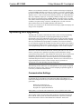
Physical Description
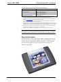
The touchpanel has a 5.7-inch (14.48 cm) active matrix color display panel with 320
x 240 resolution and 16-bit non-palette graphics. The electronic hardware is housed
in a black and silver molded plastic enclosure, shown below. Connectors to power
the unit and upload touchscreen projects are located on the sides of the unit.
Physical View of ST-1700C
Operations Guide – DOC. 6225A 1-Way Wireless RF Touchpanel: ST-1700C • 3

1-Way Wireless RF Touchpanel Crestron ST-1700C
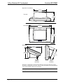
Physical Views (continued)
3.56 in
(9.04 cm)
8.75 in
(22.22 cm)
5.70 in
(14.48 cm)
Top view
Front view
Side views
3.85 in
(9.78 cm)
5.51 in
(14.00 cm)
4.24 in
(10.76 cm)
5.01 in
(12.73 cm)
upload
connector
Cresnet
Power
connector
The battery compartment, located on the underside of the unit, holds one Crestron
ST-BTPN, rechargeable power pack. There are also four rubber feet on the underside
of the unit for stability and to prevent slippage.
WARNING: To avoid shock hazard and possible damage to the unit, do not use
touchpanel in rain or expose it to unnecessary moisture.
4 • 1-Way Wireless RF Touchpanel: ST-1700C Operations Guide – DOC. 6225A

Crestron ST-1700C 1-Way Wireless RF Touchpanel
Industry Compliance
As of the date of manufacture, this unit has been tested and found to comply with
specifications for CE marking and standards per EMC and Radio Communications
Compliance Labeling.
NOTE: This device complies with part 15 of the FCC rules. Operation is subject to
the following two conditions: (1) this device may not cause harmful interference, and
(2) this device must accept any interference received, including interference that may
cause undesired operation.
NOTE: This equipment has been tested and found to comply with the limits for a
Class B digital device, pursuant to part 15 of the FCC Rules. These limits are
designed to provide reasonable protection against harmful interference in a
residential installation. The equipment generates, uses and can radiate radio
frequency energy and, if not installed and used in accordance with the instructions,
may cause harmful interference to radio communications. However, there is no
guarantee that interference will not occur in a particular installation. If this
equipment does cause harmful interference to radio or television reception, which
can determined by turning the equipment off and on, the user is encouraged to try to
correct the interference by one or more of the following measures:
Reorient or relocate the receiving antenna.
Increase the separation between the equipment and receiver.
Connect the equipment into an outlet on a circuit different from that to which the
receiver is connected.
Consult the dealer or an experienced radio/TV technician for help.
Setup
Applying Power
The touchpanel can be powered via the supplied external AC power pack, the
ST-DSN docking station, or via the ST-BTPN battery pack. Each of these supplied
items has its own guide which details proper usage. Refer to the following table for
the required document number.
NOTE: The battery can be charged only if the touchpanel is in the docking station.
The touchpanel will function when powered by the external power pack, but this
configuration will not charge the battery.
Operations Guide – DOC. 6225A 1-Way Wireless RF Touchpanel: ST-1700C • 5

1-Way Wireless RF Touchpanel Crestron ST-1700C
ST-1700C Power Source Options
POWER SOURCE OPTION MODEL
DOCUMENT
NUMBER *
Battery Pack** ST-BTPN 6088
Docking Station ST-DSN 6095
Domestic External Power Pack or PW-1215 5762
International External Power Pack PWI-1215 5763
* The latest revision may have a revision letter after the document number (i.e., 6088A).
**
The battery pack does not “trickle” charge when the external power pack is used to power the
touchpanel.
Identity Codes
The ST-1700C touchpanel uses two distinct types of identity codes: Cresnet identity
(Net ID or Cresnet ID), and RF ID. These codes are assigned to the touchpanel from
the Interface Submenu when the unit is configured. Refer to “Setup Menu” on page
7. For the touchpanel to be identified within the Cresnet system, these assignments
must match assignments made in the SIMPL Windows program.
Net ID
Every equipment and user interface within the Cresnet system requires a unique Net
ID. The Net ID is a two-digit hexadecimal number that can range from 03 to FE. The
Net ID of the unit must match the Net ID specified in the SIMPL Windows program.
The Net ID is used when the touchpanel is wired directly to the control system
during uploading a Crestron VisionTools
®
Pro-e (VT Pro-e) project or upgrading the
touchpanel firmware.
RF ID
Every ST-1700C touchpanel communicating with a Cresnet control system via a
CNRFGWA requires a unique RF ID to secure RF communications. There are 15
useable codes (two-digit hexadecimal numbers) for multiple touchpanel(s) ranging
from 10 to 0F in most significant digit increments (i.e., 10, 20, 30, . . . F0). The RF
ID of the unit must match the RF ID specified in the SIMPL Windows program.
NOTE: Do not set the RF ID to “00”; it is not supported in SIMPL Windows.
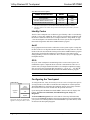
Configuring the Touchpanel
MAIN MENU
This menu can also be obtained via
digital reserved join number, 17242.
To configure the unit, it may be necessary to access a series of setup screens prior to
viewing run-time screens that are loaded into the touchpanel for normal operation.
The MAIN MENU for configuring the touchpanel appears when a finger is held to
the touchscreen for about five seconds from the powered down state.
Upon entering SETUP MODE, the MAIN MENU, shown to the left, displays four
buttons: Touch Screen Calibration, Exit and Run Program, Setup, and
Diagnostics.
The Exit and Run Program button verifies that all of the setup information has
been saved to EEPROM and displays the main page that has been programmed into
your system. The remaining buttons on the MAIN MENU open other menus, which
are discussed in subsequent paragraphs.
6 • 1-Way Wireless RF Touchpanel: ST-1700C Operations Guide – DOC. 6225A

Crestron ST-1700C 1-Way Wireless RF Touchpanel
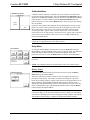
Calibration Menu
CALIBRATION MENU
Calibration of the touchscreen is required if the active touch area of a button does
not coincide with the button's image. Select the Touch Screen Calibration
b
utton to
display the CALIBRATION MENU, shown to the left. The CALIBRATION MENU
offers the choice to initiate calibration with the Perform Calibration button or
return to the previous screen with the Return button. Choose an option by touching
the correct button.
If you proceed to calibrate the touchpanel, the screen displays the message "Touch
Upper Left" centered on the panel with a cross hair in the upper left corner. Touch
the cross hair in the corner of the screen to initiate calibration. Another message,
"Touch Upper right", appears with a cross hair in the correct corner. Touch the
corner of the screen. A final message, “Touch Lower Left”, appears with a cross hair
in the correct corner. Touch the corner of the screen to conclude calibration and
return to the MAIN MENU.
NOTE: When touching the screen during calibration, be as accurate as possible.
Use the tip of a capped pen or the eraser end of a pencil.
Setup Menu
SETUP MENU
To obtain the SETUP MENU, shown to the left, press the Setup button from the
MAIN MENU. The SETUP MENU offers a series of buttons, which open additional
menus and displays that are detailed in subsequent paragraphs. After setup
parameters have been set, select the Return button to return to the MAIN MENU.
NOTE: For convenience, the current CRESNET ID setting is displayed in the lower
left corner.
NOTE: All touchpanel settings are automatically saved in non-volatile memory.
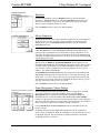
Battery Status
BATTERY STATUS
To access the BATTERY STATUS screen, shown to the left, press the Battery
Status button on the SETUP MENU.
This screen indicates the amount of charge (or life) remaining in the battery as a
percentage of full capacity, if the battery is installed. An analog bar is provided
below the percentage amount as a quick visual reference to the approximate level of
charge remaining. The EXTERNAL POWER label appears if external power is
applied either through the docking station or via the optional power pack. Note that
battery recharging takes place only through the docking station. Touch the Return
button to display the SETUP MENU.
NOTE: When the touchpanel is in the docking station to recharge the battery, the %
CAPACITY display is not an accurate indicator of battery charge level. The display
will indicate a full charge (100%) before charging is actually complete. The docking
station indicates that charging is complete by illuminating the RDY indicator.
Operations Guide – DOC. 6225A 1-Way Wireless RF Touchpanel: ST-1700C • 7

1-Way Wireless RF Touchpanel Crestron ST-1700C
Select Interface
SELECT INTERFACE
CRESNET INTERFACE MENU
SELECT RF ID
The touchpanel communicates with a control system to activate commands or to
display feedback from components within the system. The communication interface
must be correctly specified or communication will not occur. To set communication
parameters, first select the Interface button on the SETUP MENU to display the
SELECT INTERFACE screen, shown to the left. Then, select either the CRESNET
or the RF button to display the CRESNET INTERFACE MENU or the SELECT RF
ID screen, respectively. Use these screens to set the Cresnet network identity (Net
ID) and the RF ID numbers.
Cresnet Interface Menu
CRESNET ID is a two-digit hexadecimal number that can range from 03 to FE, used
only during screen uploads to the touchpanel or upgrading the touchpanel firmware.
Net ID for the ST-1700C is factory set to 03.
The UP and DOWN buttons increase and decrease the CRESNET ID by one digit
(i.e., 03, 04, 05, . . . FE).
Select the Return button to return to the SELECT INTERFACE screen.
RF Setup
RF ID, the radio frequency identity number, is necessary to secure RF
communications such that controls can be activated from the touchpanel. The RF ID
consists of a two-digit hexadecimal number. The touchpanel can be set to one of
fifteen numbers; “10” is shown as an example in the illustration and happens to be
the default. The RF ID setting should match the value assigned to the ST-1700C
touchpanel definition is the SIMPL Windows program. Refer to page 12 for
information about SIMPL programming/setup for this touchpanel.
The UP and DOWN buttons increase and decrease the RF ID most significant digit
by one, respectively (i.e., 10, 20, 30, …, F0).
After the Cresnet ID and RF ID settings have been verified, touch the Return
b
utton
to save the settings and display the SELECT INTERFACE screen.
KEY CLICK SETUP SCREEN
Key Click Setup
From the SETUP MENU, press the Key Click Enabled button to open the KEY
CLICK SETUP screen. (If the function is currently disabled, the button legend is
“Key Click Disabled.”)To enable an audible tone (beep) when the touchpanel
buttons are pressed, select among the Short, Med, or Long KEY CLICK
ENABLE/LEN buttons to set the duration of the tone. The touchpanel responds with
a corresponding signal. To disable the feature, select Click Off.
Use the KEY CLICK VOLUME UP and DOWN buttons to increase and decrease
the volume of the signal. The display to the right of the buttons shows the relative
volume from 0% to 100%, both as a numeric value and, for a quick visual reference,
as an analog bar.
Select the Return button to return to the SETUP MENU.
8 • 1-Way Wireless RF Touchpanel: ST-1700C Operations Guide – DOC. 6225A

Crestron ST-1700C 1-Way Wireless RF Touchpanel
SCREEN SETTINGS -
BRIGHTNESS
Brightness
From the SETUP MENU, press the Brightness button to open the SCREEN
SETTINGS – BRIGHTNESS screen. The UP and DOWN buttons increase and
decrease screen brightness, respectively. The display to the right of the buttons
shows the relative brightness from 0% to 100%.
Select the Return button to return to the SETUP MENU.
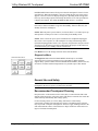
STARTUP PREFERENCE
Startup Preference
The Startup Preference feature allows (when the touchpanel is off or in standby) the
display to come on or stay off when a “quick” pushbutton is pressed. From the
SETUP MENU, press the Startup Preferences button to open the STARTUP
PREFERENCE screen.
NOTE: The “Display On From Hardkey” feature applies only to units with the
1700C-BTNB-BEZEL or 1700C-BTNB-BEZEL-BLANK option installed. These
options provide for installation of a new bezel and ten “quick” pushbuttons, five on
each side of the LCD screen. You can use these buttons to access any frequently used
commands. For detailed information, refer to the latest version of the manual supplied
with the options, Doc. 6224.
When pressed, the DISPLAY ON FROM HARDKEY button toggles between
ENABLED and DISABLED. With ENABLED selected, the display comes on when
one of the “quick” pushbuttons is pressed. With DISABLED selected, the display
stays off when a “quick” pushbutton is pressed (if touchpanel was off, it goes to
standby). The default is DISABLED.
The POWER UP ON LAST PAGE button also toggles between ENABLED and
DISABLED. Enabling this option causes the unit to “remember” the last page and
which “joins” were active when the unit was last powered down, and return to that
state when next powered on. If the option is disabled, the unit will always go to the
first page of the project and all “joins” are cleared.
Select the Return button to return to the SETUP MENU.
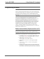
Power Management Timeout Settings
POWER MANAGEMENT TIMEOUT
SETTINGS
The Power Management feature is intended to conserve energy and to extend the
service life of the battery. From the STARTUP screen, press the Power
Management button to display the POWER MANAGEMENT TIMEOUT
SETTINGS Screen. Use the STANDBY and POWER DOWN UP and DOWN
buttons to set the respective timeouts from 0 through 120 minutes, where 0 disables
the timeout. The time settings are in single-minute increments from 0 to ten minutes,
and in 10-minute increments from 10 minutes through 120 minutes.
Use the Standby Now and Power Down Now buttons to immediately enter the
respective mode.
STANDBY timeout turns the display and backlight off when the touchpanel is
inactive for the specified time. When the touchpanel is reactivated, the last screen to
be displayed reappears. The specified time is displayed in minutes. The default
STANDBY timeout is 10 minutes.
Operations Guide – DOC. 6225A 1-Way Wireless RF Touchpanel: ST-1700C • 9

1-Way Wireless RF Touchpanel Crestron ST-1700C
POWER DOWN timeout turns off all power when the touchpanel is inactive for the
specified time. When the touchpanel is activated, either the first page of the project
appears or the last screen to be displayed reappears, depending on the setting of the
Power Up On Last Page option on the Startup Preference screen. The specified time
is displayed in minutes. The default POWER DOWN timeout is 30 minutes.
NOTE: Power Down Timeout should be set low to maximize battery life. However,
Power Down Timeout should be set greater than Standby Timeout. Otherwise, the
Standby Timeout is meaningless.
NOTE: When the panel is powered down, it will take about 1.5 seconds to power up
and respond to a button press. There is no such delay from Standby mode.
NOTE: If the external AC power pack is attached to the touchpanel and plugged
into an active AC receptacle, or if the touchpanel is resting in the docking station
(ST-DSN) and plugged into an active AC receptacle, the panel does not power down
when the power down timeout is achieved. Recall that the purpose of this timeout is
to maximize battery life. Standby timeout still functions.
Press Return to save the settings and return to the SETUP MENU.
Diagnostics Menu
DIAGNOSTICS MENU
The Diagnostics button from the MAIN MENU should only be used under
supervision from a Crestron customer service representative during telephone
support. Many options available from the DIAGNOSTICS MENU, shown to the left,
are numeric in nature and their interpretation is beyond the scope of this manual.
General Use and Safety
WARNING: To avoid shock hazard and possible damage to the unit, do not use the
touchpanel in the rain or expose it to unnecessary moisture.
Recommended Touchpanel Cleaning
Keep the surface of the touchscreen free of dirt, dust, or other materials that could
degrade optical properties. Long-term contact with abrasive materials can scratch the
surface that may detrimentally affect image quality.
For best cleaning results, use a clean, damp, non-abrasive cloth with any
commercially available non-ammonia glass cleaner. Surrounding plastic enclosure
may not provide a complete watertight seal. Therefore, apply cleaning solution to the
cloth rather than the surface of the touchscreen. Wipe touchscreen clean and avoid
ingress of moisture beneath panels.
10 • 1-Way Wireless RF Touchpanel: ST-1700C Operations Guide – DOC. 6225A

Crestron ST-1700C 1-Way Wireless RF Touchpanel
Programming Software
Have a question or comment about Crestron software?
Answers to frequently asked questions (FAQs) can be viewed in the Online Help
section of the Crestron website (www.crestron.com). To post your own question or
view questions you have submitted to Crestron’s True Blue Support, log in at
http://www.crestron.com/accounts/login.asp. First-time users will need to establish a
user account.
You can create a program that allows you to set up the ST-1700C to operate a
Crestron control system using the Crestron programming tools Crestron
SystemBuilder™ and SIMPL Windows. These tools are intended for users with
different levels of programming knowledge. The flexibility of each tool is
proportional to the degree of programming expertise (i.e., the more flexible, the
more a programmer needs to know and account for). Of course, one can initiate
programming using the easiest method (SystemBuilder) and use advanced
techniques that are available from SIMPL Windows to customize the job.
VT Pro-e is a Windows compatible software package for creating Crestron
touchpanel screen designs. Refer to “Programming with VT Pro-e” on page 15 for
additional details regarding VT Pro-e.
Earliest Version Software Requirements for the PC
NOTE: Crestron recommends that you use the latest software to take advantage of
the most recently released features. The latest software is available from the
Downloads | Software Updates section of the Crestron website (www.crestron.com).
The following are recommended software version requirements for the PC:
• SystemBuilder version 1.02 or later. Requires SIMPL Windows and
Crestron Engraver. Requires SystemBuilder templates 1.01 or later.
• SIMPL Windows version 2.05.22 or later.
Requires SIMPL+ Cross Compiler version 1.1.
• Crestron Database version 16.2.1 or later. Required by SIMPL
Windows.
• VisionTools Pro-e version 3.2.1.8 or later. Used for graphical
touchscreen design.
• (Optional) Crestron Engraver version 2.3.0.0 (only required if using
SystemBuilder or if optional hard buttons and bezel are installed, and
1700C-BTNB or 1700C-BTNS engraveable button kits are purchased).
Operations Guide – DOC. 6225A 1-Way Wireless RF Touchpanel: ST-1700C • 11

1-Way Wireless RF Touchpanel Crestron ST-1700C
Programming with Crestron SystemBuilder
The easiest method of
p
rogramming, but does not
offer as much flexibility as
SIMPL Windows.
Crestron SystemBuilder offers automatic programming for such residential and
commercial applications as audio distribution, home theater, video conferencing, and
lighting. The interface of this tool guides you through a few basic steps for
designating rooms and specifying the control system, touchpanels, devices, and
functionality. Crestron SystemBuilder then programs the system, including all
touchpanel projects and control system logic.
Crestron SystemBuilder is fully integrated with Crestron's suite of software
development tools, including SIMPL Windows, VT Pro-e, Crestron Engraver,
Crestron Database, User IR Database, and User Modules Directory. Crestron
SystemBuilder accesses these tools behind the scenes, enabling you to easily create
robust systems.
Programming with SIMPL Windows
NOTE: The following assumes that the reader has knowledge of SIMPL Windows.
If not, refer to the extensive help information provided with the software.
NOTE: In the following description, the PRO2 control system is used.
SIMPL Windows is Crestron's software for programming Crestron control systems.
It provides a well-designed graphical environment with a number of workspaces
(i.e., windows) in which a programmer can select, configure, program, test, and
monitor a Crestron control system. SIMPL Windows offers drag and drop
functionality in a familiar Windows
®
environment.
This section describes a sample SIMPL Windows program that includes a
touchpanel.
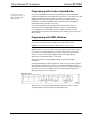
Configuration Manager is where programmers “build” a Crestron control system by
selecting hardware from the Device Library. In Configuration Manager, drag the
PRO2 from the Control Systems folder of the Device Library and drop it in the upper
pane of the System Views. The PRO2 with its associated communication ports is
displayed in the System Views upper pane.
PRO2 System View
The System Views lower pane displays the PRO2 system tree. This tree can be
expanded to display and configure the communications ports.
12 • 1-Way Wireless RF Touchpanel: ST-1700C Operations Guide – DOC. 6225A

Crestron ST-1700C 1-Way Wireless RF Touchpanel
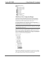
Expanded PRO2 System Tree
C2Net-Device Slot in Configuration Manager
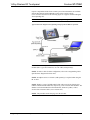
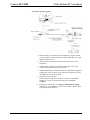
To incorporate a wireless RF touchpanel into the system, a gateway device is
required. The C2Net-Device Slot can accept a gateway such as the CNRFGWA.
Once a gateway is configured in a C2Net-Device Slot, the slot allows Cresnet
communication between the touchpanel and the control system.
In Configuration Manager, drag the CNRFGWA gateway from the Wireless
Receivers (RF) folder of the Device Library. The System Views upper pane displays
the CNRFGWA device icon below the PRO2 graphic.
NOTE: An ST-CP control processor is automatically configured with a CNRFGWA
in its STCP-Net Device Slot 3, with a fixed Net ID of 2, when the ST-CP is dragged
into the upper pane of System Views.
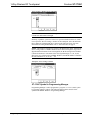
Drag the ST-1700C from the Touchpanels (Wireless | Wireless one way) folder of
the Device Library and drop it on the CNRFGWA symbol in System Views. The
PRO2 system tree displays the CNRFGWA gateway in Slot 9, with a default Net ID
of 24. The CNRFGWA displays the touchpanel at the touchpanel’s default RF ID
location, “10,” as shown in the following illustration.
C2Net Device, Slot 9
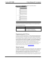
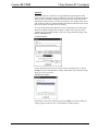
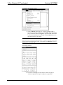
Double-click the CNRFGWA icon in the upper pane to open the “Device Settings”
window. This window displays CNRFGWA device information. Select the Net ID
tab to change the gateway Net ID, as shown in the following figure.
Operations Guide – DOC. 6225A 1-Way Wireless RF Touchpanel: ST-1700C • 13

1-Way Wireless RF Touchpanel Crestron ST-1700C
“Device Settings” Window for the CNRFGWA
NOTE: Recall that if the CNRFGWA is part of an ST-CP configuration, its Net ID
is fixed at 02 and cannot be changed.
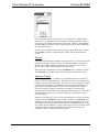
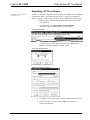
Similarly, expand the system tree in the lower pane and double-click the ST-1700C
icon to open the “Device Settings” window for the touchpanel. Select the RF/IR ID
tab to change the touchpanel RF ID, as shown in the following figure. For more
information on setting the RF/IR ID, refer to “Select Interface” on page 8.
NOTE: The hardware and software settings of the RF ID must match. Although the
device setting window in SIMPL Windows allows choices through the range of two-
digit Hexadecimal numbers from 01 through FE, the RF ID setting for the hardware
is limited to numbers in increments of the most significant digit (i.e., 00, 10, 20).
Since 00 is not a valid selection in SIMPL Windows, the RF ID number is limited to
the fifteen numbers 10, 20, 30, 40, . . .F0.
Touchpanel “Device Settings” Window
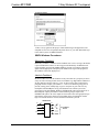
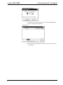
ST-1700C Symbol in Programming Manager
Programming Manager is where programmers “program” a Crestron control system
by assigning signals to symbols. The following diagram shows the ST-1700C
symbol in the SIMPL Windows’ Programming Manager.
14 • 1-Way Wireless RF Touchpanel: ST-1700C Operations Guide – DOC. 6225A

Crestron ST-1700C 1-Way Wireless RF Touchpanel
Detail View of the ST-1700C in SIMPL Windows’ Programming Manager
NOTE: Join numbers are expandable to 999.
The table below lists and gives functional descriptions for the touchpanel outputs.
Symbol Output Signal Descriptions
OUTPUT DESCRIPTION
press 1 through press 32* Notifies control system of button press (1 – 32*).
High/1 = button is being pressed
Low/0 = button is not being pressed
* Expandable to 999
Programming with VT Pro-e
Control screen variations incorporating two- and three-dimensional graphics and text
are possible and can be created with VT Pro-e, a design and programming Windows-
based software program. A set of pages, which make up a project, can be designed
for each application. Each touchpanel can be organized with the ideal, color-oriented
control environment with custom control graphics: icons, two and three-dimensional
buttons, and floor plans. The project is uploaded to the touchpanel’s flash PROM.
The touchpanel uses the project until another is uploaded from the PC. The PC may
be disconnected from the control processor except when uploading a project.
For additional software information, refer to the help file provided with the software.
The latest version of VT Pro-e can be obtained from the Downloads | Software
Updates section of the Crestron website (www.crestron.com)
.
Virtual Feedback
Programming a one-way RF touchpanel such as the ST-1700C requires consideration
of “feedback." Since the panels are one-way only, and there is no true feedback, you
must create "virtual feedback" so that buttons respond appropriately when pressed
and the user perceives no real difference between a one-way panel and a two-way
panel. SystemBuilder takes care of all of this for you. However, if you are
programming your panels with SIMPL Windows and VT Pro-e, you must follow the
procedure described on the next page to add logic both to the touchpanel for button
Operations Guide – DOC. 6225A 1-Way Wireless RF Touchpanel: ST-1700C • 15

1-Way Wireless RF Touchpanel Crestron ST-1700C
feedback and to the control system program to properly process the signals, and to
make sure that the state of the buttons on the panel and in the control system remain
in sync.
Button press feedback produces a change in appearance from the inactive state to the
active state, or vice versa, as defined in the program.
• Momentary feedback, from inactive to active and back to inactive, has
a short duration, lasting only as long as the button is pressed.
• Toggle feedback produces a change of state each time the button is
pressed.
• With Interlock feedback, only one button in an assigned interlock group
can be active at a time. Pressing an inactive button changes its state to
active, and forces the other buttons in the group to inactive. (To clear
all buttons in the interlock group requires that an extra button be added
whose sole purpose is to force all the others to the inactive state.)
• Duration feedback is assigned to a button that is to be activated and
remain active for a specified period of time, and then return to the
inactive state.
In the following paragraphs, each feedback type will be discussed in detail as
applicable.
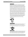
VT Pro-e Procedures
Buttons requiring feedback need to have the feedback type assigned as if it were a
property of the object. Button feedback logic is classified as momentary, toggle,
interlock, or duration. Logic is added to the buttons on the panel (after join numbers
and other properties have been assigned), by right-clicking the button in VT Pro-e
and selecting Feedback, which displays the “Feedback” window.
“Feedback” Window
NOTE: When the Feedback window is open, you can click on any of the buttons on
the page and view their various feedback properties.
16 • 1-Way Wireless RF Touchpanel: ST-1700C Operations Guide – DOC. 6225A
Page is loading ...
Page is loading ...
Page is loading ...
Page is loading ...
Page is loading ...
Page is loading ...
Page is loading ...
Page is loading ...
Page is loading ...
Page is loading ...
Page is loading ...
Page is loading ...
Page is loading ...
Page is loading ...
Page is loading ...
Page is loading ...
Page is loading ...
Page is loading ...
Page is loading ...
Page is loading ...
-
 1
1
-
 2
2
-
 3
3
-
 4
4
-
 5
5
-
 6
6
-
 7
7
-
 8
8
-
 9
9
-
 10
10
-
 11
11
-
 12
12
-
 13
13
-
 14
14
-
 15
15
-
 16
16
-
 17
17
-
 18
18
-
 19
19
-
 20
20
-
 21
21
-
 22
22
-
 23
23
-
 24
24
-
 25
25
-
 26
26
-
 27
27
-
 28
28
-
 29
29
-
 30
30
-
 31
31
-
 32
32
-
 33
33
-
 34
34
-
 35
35
-
 36
36
-
 37
37
-
 38
38
-
 39
39
-
 40
40


Crestron ST-1700C User manual
- Category
- Mobile device dock stations
- Type
- User manual
- This manual is also suitable for
Ask a question and I''ll find the answer in the document
Finding information in a document is now easier with AI
Related papers
-
Crestron STX-1700C User manual
-
Crestron TPS-6X-FP User manual
-
-
-
-
-
-
-
-
Other documents
-
Lenovo 80HW003CGE Datasheet
-
Bosch SSB800/ 1000/ 1000TL Touch Screen Firmware Update Operating instructions
-
Belkin F5U103WINXP Installation guide
-
 Inepro PRO2 Series User manual
-
 Crestron electronic CLS-C6 User manual
-
Yamaha Example Programs (Crestron) - Setup Guide Installation guide
-
Contec PWI-60D6D2 Owner's manual
-
Sharper Image Cordless Split End Hair Trimmer Owner's manual
-
 Audioaccess PX-700 User manual
-
janitza Firmware Updates Operating instructions


