Sears 113197211 User manual

Category
Circular saws
Type
User manual
SFo_u_h_'_e"_r"unle_
SWA/_S
owner's
manual
CATALOG NO.
9-29012
9-29013
FITSTHE FOLLOWING
MODEL NUMBERS:
113.197110, 113.197111
113.197150, 113.197151
113.197210, 113.197211
113.197250, 113_197251
113.197410, 113.197411
113.197510, 113.197511
113.197610, 113.197611
113.197180, 113.197181
FOR YOUR
SAFETY:
SEA/A_S/ I:RRFT$MgN_
10-INCH RADIAL SAW
GUARD KIT
assembly
operating
repair parts
READ ALL
INSTRUCTIONS
CAREFULLY
Sold by SEARS, ROEBUCK AND CO., Chicago, IL 60684 U.S.A.
Part No. SP5623 Printed in USA
Table of Contents
Section Title ................................................................................ Page
Safety ........................................................................................................................ 3
Assembly .................................................................................................................. 8
Repair Parts ............................................................................................................ 17
iiillllllllllllllllll ii ii ............................
FULL ONE YEAR WARRANTY ON CRAFTSMAN RADIAL ARM SAW GUARD KIT
If within one year from the date of purchase, this Craftsman Radial Saw Guard
Kit fails due to a defect in material or workmanship, Sears will repair it, free of
charge.
WARRANTY SERVICE IS AVAILABLE BY SIMPLY CONTACTING THE
NEAREST SEARS SERVICE CENTER/DEPARTMENT THROUGHOUT THE
UNITED STATES.
This warranty applies only while this product is used in the United States.
This warranty gives you specific legal rights and you may also have other rights
which vary from state to state.
SEARS, ROEBUCK AND CO. D/817 WA
Hoffman Estates, IL 60195
iiiiii, i1,1 ii1,111 iiiii ,i ii i i i,iii1,1111,1,11,ii, i,,i
Safety
This manual has safety information and
ins_ctions to help users eliminate or reduce
the risk of accidents and injuries, including:
1. Severe cuts, and loss of fingers or other
body parts due to contact with the blade.
2. Eye impact injuries, and blindness, from
being hit by a thrown workpiece, workpiece
chips or pieces of blade,
3. Bodily impact injuries, broken bones, and
internal organ damage from being hit by a
thrown workpiece
4. Shock or electrocution
5. Bums.
Major Hazards
Three major hazards are associated with
using the radial arm saw for ripping, They
are ouffeed zone hazard, kickback, and
wrong way feed.
This section only briefly explains these haz-
ards. Read the ripping and crosscutting safe-
ty sections of your saw manual for more
detailed explanations of these and other haz-
ards.
Outfeed Zone Hazard
,i_t,DANGER
Safety Symbol and Signal Words
An exclamation mark inside a triangle is the
safety alert symbol.
It is used to draw attention to safety informa-
tion in the manual and on the saw_ It is
followed by a signal word, DANGER,
WARNING, or CAUTION, which tells the
level of risk:
,_ DANGER: means if the safety infor-
mation is not followed someone will be seri-
ously injured or killed.
WARNING: means if the safety infor-
mation is not followed someone could be
seriously injured or killed.
,,Ik
,_ CAUTION: means if the safety infor-
mation is not followed someone might be
injured.
Read and follow all safety information
and instructions.
If you reach around the blade to the outfeed
side when ripping, and try to hold down or
pull the workpiece through to complete a
cut, the rotational force of the blade will pull
your hand back into the blade.
Fingers will be cut off.
Safety
Kickback Hazard
Kickback is the uncontrolled p_opelling of
the workpiece back toward the user' during
ripping°
The cause of kickback is the binding or
pinching of the blade in the workpiece°
Several conditions can cause the blade to
bind or pinch.
When a workpiece kicks back, it could hit
hard enough to cause internal organ injury,
broken bones, or death.
kWARNING
KICKBACKII
Wrong Way Feed Hazard
Wrong way feed is ripping by feeding the
workpiece into the outfeed side of the blade.
The rotational force of the blade can grab
and pull the workpiece.
Before you can let go or pull back, the force
could pull your hand along with the work-
piece into the blade. Fingers or hand could
be cut off.
The propelled workpiece could hit a by-
stander, causing severe impact injury or
death_
kWARNING
Wrong Way Feed
Safety Instructions
Read and follow all safety instructions,
Personal Safety Instructions
1. Wear"safety goggles labeled "ANSI
Z87.1" on the package, tt means the goggles
meet impact standards set by the American
National Standards Institute. Regular eye-
glasses are not safety goggles.
2. Wear close fitting clothes, short sleeved
shirts, and non-slip shoes. Tie up long hair.
Do not wear gloves, ties, .jewelry, loose
clothing, or long sleeves. These can get
caught in the spinning blade and pull body
parts into dae blade.
3. Wear dust mask to keep from inhaling
fine particles.
4. Wear ear protectors, plugs or muffs if' you
use saw daily.
5. Keep good fboting and balance; do not
over-reach.
Work Area Safety Instructions
1. Keep children, pets, and visitors out of
work area; they could be tilt by a thrown
workpiece, workpiece chips or pieces of
blade.
2. Turn saw off, remove yellow key, and
unplug before leaving work area. Do not
leave until blade has stopped spinning.
3. Make work area child-proof: remove yel-
low key to prevent accidental start-up; store
key out of sight and reach; lock work area.
4. Keep floors clean and flee of sawdust,
wax and other slippery materials.
5. Keep work area well lighted and unclut-
tered,
6. Use saw only in dry area. Do not use in
wet or damp areas.
\
Dust Mask
Ear Proleclors
Safety
Safety
Saw Safety Instructions
1_Use guard, pawls and riving knife accord-
ing to instructions. Keep them in working
order.
2_Routinely check saw for broken or dam-
aged parts. Repair or replace damaged parts
before using saw. Check new or rep_ed
parts fbr alignment, binding, and correct
installation.
3. Unplug saw before doing maintenance,
making adjustments, correcting alignment,
or changing blades.
4. Do not force saw. Use saw, blades and
accessories only as intended.
5. Have yellow key out and saw switched off
before plugging in power cord.
6. Before turning on saw, clear table of all
objects except workpiece to be cut and nec-
essary fixtures, clamps, or feather-boardso
7. If blade jams, turn saw off immediately,
remove yellow key, the free blade. Do not
try to free blade with saw on.
8_Turn saw off if it vibrates too much or
makes an odd sound° CorT_t any problem
before restarting saw.
9. Do not layout, assemble, or setup work
with saw on, or while blade is spinning.
10. Keep saw table clean.
11. Store items away from saw. Do not
climb on saw or stand on saw table to reach
items because saw can tip over.
Workpiece Safety Instructions
!. Cut only wood, woodlike or plastic mate-
rials.. Do not cut met'_
2. Cut only one workpiece at a time.
Stacking or placing workpieces edge to edge
can cause user to lose control of workpieceo
Safety
3. Rip only workpieces longer than the
diameter of the blade. Do not rip workpieces
that are shorter than the diameter of the
blade being used.
4. Workpieces that extend beyond the saw
table can shift, twist, rise up from the table,
or fall as they ar'e cut or afterwards. Support
workpiece with table extensions the same
height as the saw table.
5. To prevent tipping, support outer ends of
extensions with sturdy legs or an outrigger.
6. Do not use another person to help support
workpieces or to aid by pushing or pulling
on workpieces, because these actions can
cause kickback. Use table extensions.
7. Use clamps or vice to hold workpiece. It's
safer than using your hands.
Blade Safety Instructions
1.Use only blades marked for at least 3450
rpmo
2. Use only 10" or smaller diameter blades.
3. Use blades for their recommended cutting
procedures.
4. Keep blade sharp and clean.
5. Do not overtighten blade nut because
blade collar could warp°
6o Do not turn saw on and off in rapid
sequence because blade can loosen.
7. Blade should stop within 15 seconds after
saw is switched off. If blade takes longer, the
saw needs repair. Contact Sears Service
Center.
Assembly
Identify Parts
3he h_!lowing paris are inchided:
Nole: B@nv beginning assembl3; check that all parts are included If you ate missing at O, part, do
m_t assemble guar_L _mtact your Sear_ Service Center to get the missing part. Sonlethnes snlall
parts can get lost in packaging material. Do not throw away any packaging until guar'd is put
toRethet: Check packaging for' missing palts bcjbre contacting Sears, A COnlplete parts list (Repair
Parts) is at the end oJ the nlanual. Use the list to identij], the nuntber of the missblg part.
IJst of hmse parts with catalog #9-29012
A_ Guard Assembly ................. I
B Rear Table 40" ......................I
C SpacerT_d_Ic 40". ..................1
D. Izront Fable 40" .....................I
E Tahte Supporl ........................2
I;. Handle Assembly ................ 1
G. Bag Ol Loose Parts ........... I
Conlaining:
II,.Adapter Motor Key ........... I
I Screw Pan lid Ty T
6-32 x 1/2 ............................... 1
l Screw Flal Hd Plaslite
#1() x 3/4 ............................... 2
K fi2e Nu| ................................. I
l. Bag Ol Loose Paris ................ 1
Conlaining:
M, Guard Accessory ................ I
No Screw Plaslile #8 x 1/2 ...... 1
O. Washer 3/t6 x I x 1116....... 1
P, Owners Manual ................. 1
lJst of hmse parts with catalog #9-29013
A, Guard Assembly ................. 1
B Rear T_tble 44" ................... 1
C, Spacer Table 44" ................. 1
I), Front Table 44" .................. l
I;. tlandte Assembly .............. 1
G Bag Ol Loose Parts ............ 1
Conlaining:
I1, Adapter Motor Key ............. 1
1 Screw Pan Hd Ty T
6-32 x I/2 .............................. t
l Screw Flat Hd Plastile
#1() x 3/4 .............................. 2
K Iixe Nut .....................................t
l_Bag Ol: l_oose Paris .............. 1
Containing:
M, Guard Accessory ................ I
N Sc_cw Plaslite #8 x 1/2 ...... 1
() Washer 3116 x I x 1/16 ....... 1
P, ()whets Mamml ......................t
!
B
C
d K _ N
Assembly
Guard Installation Steps
1. Remove existing table boards. Keep all
screws, nuts and washers, including the lev-
elling screws in the center of the front table.
Discard the old table boards but keep the
fence.
2o 40" TABLE ONLY (if you have the 44"
table, skip to next step):
- Remove the table support channels,
keeping the screws, nuts and washers°
Discard the old channels.
- Install the new support channels.
- Referring to your saw owners manual,
level the channels and tighten them in
place.
Install the tee nut into the front table
board.
Refering to your saw owners manua!,
install and level the table boards.
3.44" TABLE ONLY (if you have the 40"
table, skip to next step):
Position the flont table and insert the
front two screws. The rear screw holes
in the table do not line up on any holes
in the saw base,
Using the rear screw holes as a drill
guide, drill a .5/16" hole in the saw base
for each of the two rear screws.
Remove the front table.
The U-Clips that were used as nuts for
the rear screws must be moved to the
new screw location° Remove them
from the saw and reinstall them on the
holes you .just drilled,
Install the tee nut into the front table
board.
Referring to your saw owners manual,
install and level the table boards.
4, The saw's crosscut travel may no Ionger
be square. Referring to your saw owners
manual, square the crosscut tlavel.
.5. Remove the existing guard and blade.
Rotate the saw to the outrip position.
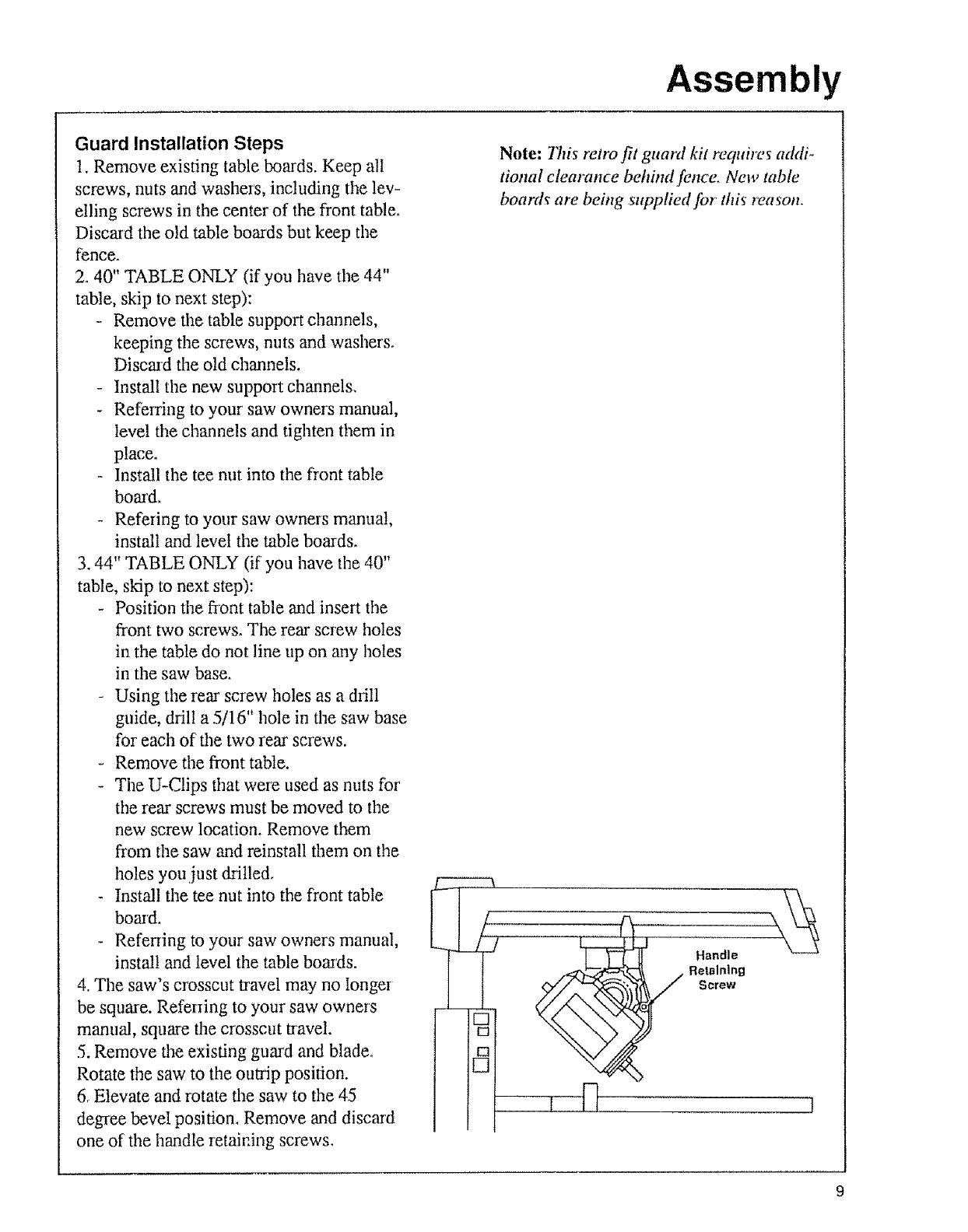
6, Elevate and rotate the saw to the 45
degree bevel position, Remove and discard
one of the handle retaining screws,
C
Note: This retro fit guard kit requires addi-
tional clearance behhM fence, New table
boards are being supplied for this reason,
c
C
.... I [-]
Handle
Retaining
Screw
Assembly
7, Rotate the saw to the negative 45 degree
l_'cx,_c!position. Remove and discmd ttle
oflmr lmndle retaining screw, Discard tile old
handle,
8. Using the two #1(1 x 3/4 flat head screws
provided, altach the new h;mdle in tile same
way as the old one was renloved,
9o Return lhe saw to the blade vertical, cross-
cut position.
10, Remove the top motor cover screw and
lock washer: Keep the washer, Discard the
old screw,
11, Install the adapter: Tile two ends of' tile
adapter fh into tile center cooling slots of the
motor; then the adapter is rotated tip into
phlce.
12. Install the replacement screw (#6 x 1/2")
with the old lock washer into the top motor
cover hole. This locks tile adapter in place.
13, Reinstall the blade°
Note: Tim rip scale fi_r the fi'ont fence posi-
tirol i._no longer cotvect Subtract 1-1/8"
fiom the ._'cale reading to obtain the correct
reading,
Install Guard
The guard is a very important safety feature_
It covers a large part of tile blade and helps
protect against severe cuts, Always use the
gumd.
1.Lock motor at 0° bevel (blade vertical).
2, Use one hand to lift cleaa" plastic guard;
use od_er hand to grasp fear of guard (below
dust elbow). Position guard so riving knife
fuces front of saw.
3oTilt fiont of guard down about 45°; place
over' blade; rotate guard to level position,
Nole: Make .uae notch in guardfits onto tab
on motor adapter. This wUlprevent move-
merit o/guard about motor Squeeze handle
u'igger to make sure it raises clear plas-tic
guard l[ it &_es ,tot, remove and re-install
gtuud, makiltg sure that trigger mechanism
engages pull link on guard,
-'LTighten guard clamp screw,
Motor Cover
Panel
Top Motor
Cover Screw
Parallel
10
Alignment
Align Riving Knife to Blade
The goa! of this adjustment is to position the
riving knife directly in line with the blade.
Riving knife alignment is an important safe-
ty factor, The riving knife rides in the kerf of
the cut work_iece during ripping to keep the
two sides of the workpiece from pinching on
the blade. Blade pinching is a cause of kick-
back,
1. Lock yoke in in-rip position (blade
towards column, motor towards front of
arm).
2. Lower arm until blade just clears table,
3. Unlock rip lock while holding up lower
plastic guard, move yoke back until blade
touches fence. Lock rip lock.
4. Loosen pawls/riving knife knob. Lower
riving knife to the table and tighten knob.
The riving "knife should rest fiat against
fence,
5. If adjustment is needed:
1o)loosen riving knife bracket screw.
Z) slide riving knife so it rests against
fence.
3.) secure riving knife bracket screw,
6, Raise riving knife and tighten pawls/riv-
ing knife knob.
Wrong
Correct
Wrong
Riving Knife
Screw
11
Controls
Miter Lock
Yellow Ke
Bevel Lock
dwheel
Miter Lock
On-Off Switch
Yellow Key
Bevel Lock
Handwheel
%ble Lock
(Cabinet Model
-Not Illustrated)
Function
Frees radial arm to move; locks
in any desired position; pro-set
indexed positions at 0°, 45°L,
45°R
Turns motor on!off
Allows saw to be switched on
Frees motor to rotate; locks in
any desired position; pre-set
indexed positions at 0°, 45 °, -
45°, 90°, -90°
Raises/lowers radial arm
Frees table sections to allow
fence changing
Operation/Comments
Pull out and towards right to
unlock, push to lock
Hold in unlocked position while
moving arm
Pull on, push off
Requires yellow key
Insert into on-off switch
Remove after turning saw off
Move towards right to unlock,
towards left to lock
Support motor before unlocking
because it can swing down
quickly. Hold in unlocked posi-
tion while moving motor
Turn clockwise to raise, coun-
terclockwise to lower'
To fold handle into wheel,
squeeze red plastic ear's and
push handle; pull handle out
until ears clock into place
Pull to unlock; push to lock
12
Controls
Rip Scale & Rip Lock
Rip lnd'_a,ors .__
0
_-._.,._ Swivel
Lock
l Table Clam[
11" Thumbscre_
t
Control Function
Operation/Comments
Rip Lock
Frees carriage to move along
radial tuna; locks in position
Pull to unlock, push to lock
Lock before ripping
Rip Scale & Rip
Indicators (Non-
Electronic Models)
Tell distance between blade and
fence when saw is in in-rip or
out-rip position
Move blade carriage along arm
to align line on indicator with
desired number on scale
Swivel Lock
Frees blade carriage to rotate
between rip and crosscut posi-
tions; locks in position
Pull to unlock; push to lock
HoM in unlocked position while
moving blade carriage
Table Clamp
Thumbscrew
(Leg Set Model)
Frees table sections to allow
fence changing
Tuna clockwise to tighten, coun-
terclockwise to loosen
Saw Handle
Provides grasping surface so
blade carriage can be moved.
Contains trigger mechanism to
raise clear plastic guard,
Grasp to move blade carriage,
Squeeze trigger to raise clear
plastic guard° Clear guard must
be raised over fence to start
crosscut.
13
Controls
Control
Guard Clamp
Screw
Guard
llold Down
Knob
tlokt Down
Riving Knife
Bracket
Function
Secures guard to motor; frees
guard for removal
Protects against contact with
upper blade; partially protects
against contact with lower'
blade; acts as sawdust deflector'
Frees hold down to move up
and down; locks hold down in
place
During ripping, acts as partial
barrier' to infeed side of blade;
keeps infeed side of workpiece
from fluttering; acts as sawdust
deflector
Prevents side to side movement
of riving knife and provides
means for' adjusting alignment
Qoeration/Comm_nts
Turn counterclockwise to
loosen, clockwise to tighten
Upper part remains fixed in
level position. Notch in guard
fits securely into matching tab
on motor
Clear guard is moveable: raise
over fence at start of crosscut;
See Saw Handle; most work-
pieces will automatically raise
clear guard during ripping; See
Guard Tab
Turn counterclockwise to
loosen, clockwise to tighten
For ripping, lower hold down to
top of workpiece surface, then
raise slightly zmd lock in place.
For crosscutting lock in fully
raised position
Loosen to align riving knife,
then tighten
14
Controls
Pawls Riving
Knile Knob
Pawls
\
Riving Knife
Control
G u ard Tab
Pawls!Riving
Knife Knob
Pawls
Riving Knife
Function
Provides manual way to raise
clear plastic guard during rip-
ping when workq_iece fails to
raise it
Frees pawls and riving knife to
independently move up and
down
During ripping, slow or stop
kickback by digging into work-
piece; when lowered during
crosscutting, provide partial bar-
rier to leading edge of blade
Reduces kickback by keeping
kerr' open; when lowered during
crosscutting, provides partial
barrier to leading edge of blade
Operation[Comments
Push and hold until workpiece
clears guard, daen release
Turn countmclockwise to
loosen, clockwise to tighten
For ripping, set paw! level on
workpiece surface. For' safeo,
rea.wns set pau& b@)re rip-
ping; See Ripping Set-Up/or
details and ilhtstratim_
For ripping, lower to table
For scgeo, reasom riving knife
must be in line with hkMe. See
Aligmnent" Riving Knife to
Blade
15
Notes
16
PARTS LIST CRAFTSMAN 10" RADIAL SAW GUARD KIT
CATALOG 9-29012 & 9-29013
Always order by Part Number - Not by Key Number
Key
No
!
2
3
4
5
6
7
8
9
t0
11
12
13
14
15
1
Part
No.
818922-1
820520
820534
820533
STD55t008
346030
82051€
818169
815757
820573
820566
820572
820568
818199
821560
STD600605
820985
805548-t0
SP5623
Description
n,n i
Screw, Flat Hd Ptastite
#10 x3/4
Handle, Yoke
Spring
Trigger
* Washer, 3/16 x 3/8 x 1/32
Screw Ptastite #8 x 1/2
Bumper
Table Rear 40"
Table Rear 44"
Table Spacer 40"
Table Spacer 44"
Table Front 40"
TabJe Front 44"
Table Support (29012 Only,_
Adapter Motor Key
* Screw Pan HD Ty 'T' 6-32 x 1/2
Guard Accessory
Washer 3/16x ! x 1/16
Owners Manual (Not Shown)
* Standard Hardware item - May Be Purchased Locally,
FIGURE 1
11
15
1
\
6
7
8
9
10
5
6
Ill
28
8
9
31
PARTS LIST CRAFTSMAN 10" RADIAL SAW GUARD KIT
CATALOG 9-29012 & 9-29013
Always order by Part Number - Not by Key Number
1
33
/
34
35
33
3O
24
1
27
17
16
2O
FIGURE 2
10
11
14
13
7 6
12
in
el=l=
U)
c£)
PARTS LIST CRAFTSMAN 10" RADIAL SAW GUARD KIT
CATALOG 9-29012 & 9-29013
Always order by Part Number - Not by Key Number
FIGURE 2 - GUARD
Key Pa_
No...... No.
1
2
3
4
6
7
8
9
10
1t
12
13
14
15
16
17
821217
821313
STD551025
815865
STD601105
802392-47
808447-6
820529
STD551031
820521
820515
STD541425
815815
820517
STD512510
820512
824159
Description
Screw, Guard Clamp
1Jnk,Pull
* Washer, 17/64 x 5/8 x 1/16
Screw, Hex Washer Hd Type
"Tq_' 1/4 - 20 x 1/2
* Screw, Pan Hd Type
'_' 10-32 x 5/16
Spacer #10 x .125
Washer, Sprtng
Knob, 5/16-18
* Washer
21/64 x 5/8 x 1/16
Spacer
Knife, Riving
* Nut, Lock 1/4-20
Paw_,AKB
Bushing
* Screw, Pan Hd. 1/4-20 x 1
Ho/der, AKB
Screw, Flat Hd Type 'q-F'
1/4 - 20 x 9/16
No
2O
21
22
23
24
25
26
27
28
29
30
31
32
33
34
35
Part
No.
820519
STD551225
820530 J
60208
805641-1
STD533107
809O19-4
820532
821310
821311
821312
821314 i
63258
60413
821449
824158
t Description
in
Nut, Slotted 1/4 - 20
* Lockwasher 1/4
Support, Knife
Nut, Push 1/4
* Ring, Retaining 5/16
* Bott, R.H, Short Neck
5/16 - 18 x 5/8
Bolt, Rd Hd Short Neck
5/16 - 18 x 1_3/4
Bolt 1/4 - 20 x 1/2
Guard, Lower
Dnk
Guard
Hold Down
Elbow, Dust
Nut, Push 5/16
Nut, Square 5/16- 18
Double Lead
Strap-Retainer
* Standard Hardware ;tern - May Be Purchased Locally,
iwnlllm ii
"U
owner's
manual
SERVICE
CATALOG NO.
9-29012
9-29013
The model number of your
drill press is found at the rear
of the head
When requesting service or
ordering parts, always pro-
vide lhe following informa-
lion:
Product Type
Model Number
Part Number
Part Description
\
Part No, SP5623
f
(
I
10-1NCH RADIAL SAW
GUARD KIT
For the repair or replacement parts you need
Call 7 am -7 pro, 7 days a week
1-800-366-PART
(1-800-366-7278)
For in-home major brand repair service
Call 24 houls a day, 7 days a week
1-800-4-REPAIR
(1-800-473-7247)
For the location of a
Sears Repair Service Center in your area
Call 24 hours a day, 7 days a week
1-800-488-1222
For information on purchasing a Sears
Maintenance Agreement orto inquire
about an existing Agreement
Cal! 9 am - 5 pro, Monday-Saturday
1-800-827-6655
";'"' ,,
If,t:;I',r/;$'!:/,t'I{_t_tl
America s Repair Spec_ahsls
\ j
Sold by SEARS,ROEBUCK AND CO., Chicago, IL 60684 U.S.A.
Form No. SP5623-3 Printed in U,S,A, 5/96
  • Page 1 1
  • Page 2 2
  • Page 3 3
  • Page 4 4
  • Page 5 5
  • Page 6 6
  • Page 7 7
  • Page 8 8
  • Page 9 9
  • Page 10 10
  • Page 11 11
  • Page 12 12
  • Page 13 13
  • Page 14 14
  • Page 15 15
  • Page 16 16
  • Page 17 17
  • Page 18 18
  • Page 19 19
  • Page 20 20

Sears 113197211 User manual

Category
Circular saws
Type
User manual

Ask a question and I''ll find the answer in the document

Finding information in a document is now easier with AI