Weil-McLain SVF Stainless Vertical Firetube (1000 MBH) User manual
- Category
- Water heaters & boilers
- Type
- User manual

Model 1000 Series 1
Models 1500-3000 Series 2
Commercial Condensing
Gas-Fired Water Boilers
Boiler Manual
Manual Part Number 550-100-255/0823
!
WARNING
Installation and service of the boiler must be performed by a qualied installer or service technician.
Read all instructions, including this manual and all other information shipped with the boiler, before
installation or operation. Perform steps in the order given. Failure to comply can result in severe
personal injury, death or substantial property damage.
Now with
the NURO®
Control!

1000-3000
2 550-100-255/0823
Contents
Tools . . . . . . . . . . . . . . . . . . . . . . . . . . . 4
Abbreviations . . . . . . . . . . . . . . . . . . . . . . 4
–
Safety Signals . . . . . . . . . . . . . . . . . . . . . . 5
Please Read Before Proceeding . . . . . . . . . . . . 5
Servicing a Boiler. . . . . . . . . . . . . . . . . . . . . . . .5
Boiler Operation . . . . . . . . . . . . . . . . . . . . . . . .6
Boiler Water . . . . . . . . . . . . . . . . . . . . . . . . . .6
Commonwealth of Massachusetts . . . . . . . . . . . . . . .6
Freeze Protection Fluids . . . . . . . . . . . . . . . . . . . .6
Damage from Water Contact . . . . . . . . . . . . . . . . . .6
Frozen Water Damage . . . . . . . . . . . . . . . . . . . . .6
–
Prepare Boiler Location. . . . . . . . . . . . . . . . . 7
Installation Compliance Requirements . . . . . . . . . . . . .7
Checks Before Boiler Installation. . . . . . . . . . . . . . . .7
Flooring and Foundation . . . . . . . . . . . . . . . . . . . .8
Garage Installation . . . . . . . . . . . . . . . . . . . . . . .8
Openings . . . . . . . . . . . . . . . . . . . . . . . . . . . .8
Clearances . . . . . . . . . . . . . . . . . . . . . . . . . . .9
Air Openings . . . . . . . . . . . . . . . . . . . . . . . . .10
Preparing for Multiple Boilers. . . . . . . . . . . . . . . . . 11
Prepare the Boiler . . . . . . . . . . . . . . . . . . . 12
Removing the Boiler from the Crate . . . . . . . . . . . . . 12
Placing the Boiler. . . . . . . . . . . . . . . . . . . . . . . 12
Seismic Bracket Installation – SVF 1000. . . . . . . . . . . 14
Seismic Bracket Installation – SVF 1500-3000. . . . . . . . 15
High Altitude Installations. . . . . . . . . . . . . . . . . . . 16
Pressure Test Preparation . . . . . . . . . . . . . . . . . .16
Pressure Test Precautions . . . . . . . . . . . . . . . . . .17
Fill the Boiler . . . . . . . . . . . . . . . . . . . . . . . . .17
Hydrostatic Pressure Test . . . . . . . . . . . . . . . . . . 17
Install Water Piping . . . . . . . . . . . . . . . . . . 18
General Piping Information . . . . . . . . . . . . . . . . . . 18
Pressure and Temperature Gauge . . . . . . . . . . . . . .18
Relief Valve Installation. . . . . . . . . . . . . . . . . . . . 19
Air Inlet Adapter Installation (SVF 1000 only) . . . . . . . . 19
Pipe Sizing . . . . . . . . . . . . . . . . . . . . . . . . . .20
Expansion Tank and Make-up Water . . . . . . . . . . . . . 22
Diaphragm or Bladder Expansion Tank . . . . . . . . . . . 22
Closed-Type Expansion Tank . . . . . . . . . . . . . . . . 22
ZONE VALVE Zoning - General . . . . . . . . . . . . . . . 23
ZONE VALVE Zoning - Primary/Secondary . . . . . . . . . 24
ZONE VALVE Zoning - High-ow-rate or High-head-loss DHW
Circuits . . . . . . . . . . . . . . . . . . . . . . . . . . . .24
ZONE VALVE Zoning - Variable Primary Flow . . . . . . . .25
ZONE VALVE Zoning - Circulator Zoning, Primary/Secondary . . 26
ZONE VALVE Zoning - Radiant Heating, Primary/Secondary . .26
ZONE VALVE Zoning - Water Chiller Systems, Primary/
Secondary . . . . . . . . . . . . . . . . . . . . . . . . . . 27
Commonwealth of Massachusetts Installations. . . . . 28
Venting and Combustion Air - General. . . . . . . . 29
Code Compliance . . . . . . . . . . . . . . . . . . . . . . 29
Venting Methods . . . . . . . . . . . . . . . . . . . . . . .29
Vent and Air Piping Materials. . . . . . . . . . . . . . . . . 29
Boiler Categories . . . . . . . . . . . . . . . . . . . . . . . 29
Using a Chimney . . . . . . . . . . . . . . . . . . . . . . .30
Combustion Air Contamination . . . . . . . . . . . . . . . . 30
Vent and Air Adapters — SVF 1000 Only . . . . . . . . . . 31
PVC Piping — SVF 1000 Only . . . . . . . . . . . . . . . .31
Vent and Air Adapters — SVF 1500-3000 . . . . . . . . . . 31
Venting and Combustion Air Options . . . . . . . 32
Existing Vent System . . . . . . . . . . . . . . . . . . . . . 32
Existing Vent System Test Procedure . . . . . . . . . . . . 32
Vent and Air Piping Materials. . . . . . . . . . . . . . . . . 33
Category II Requirements . . . . . . . . . . . . . . . . . . 34
Vent and Air Terminations for Category IV . . . . . . . . . . 36
DIRECT EXHAUST – Room Air Openings (Cat. II and IV). . 37
Combustion Air Provision. . . . . . . . . . . . . . . . . . . 37
Sizing Combustion Air Openings . . . . . . . . . . . . . . . 37
Special Considerations . . . . . . . . . . . . . . . . . . . . 37
DIRECT EXHAUST – Vertical Termination (Cat. II and IV). . 39
Vertical Termination Location . . . . . . . . . . . . . . . . . 39
Vent Piping Installation . . . . . . . . . . . . . . . . . . . .40
Vent Termination Installation . . . . . . . . . . . . . . . . .40
DIRECT EXHAUST – Sidewall Termination (Category IV) . 41
Sidewall Termination Location . . . . . . . . . . . . . . . .41
Determine Termination Location . . . . . . . . . . . . . . .42
Vent Piping Installation . . . . . . . . . . . . . . . . . . . .42
Vent Termination Installation . . . . . . . . . . . . . . . . .43
DIRECT VENT – Room Air Openings (Category IV) . 44
Combustion and Ventilation Air Provision . . . . . . . . . . 44
Sizing Air Openings. . . . . . . . . . . . . . . . . . . . . . 45
Special Considerations . . . . . . . . . . . . . . . . . . . . 45
Combustion Air Manifold Option . . . . . . . . . . . . . . .45
DIRECT VENT – Vertical Termination (Category IV) . . . 46
Vertical Termination Location . . . . . . . . . . . . . . . . . 46
Vent Piping Installation . . . . . . . . . . . . . . . . . . . .46
Vent and Air Termination Installation . . . . . . . . . . . . .47
DIRECT VENT – Sidewall Termination (Category IV) . .48
Sidewall Termination Location . . . . . . . . . . . . . . . .48
Determine Termination Location . . . . . . . . . . . . . . .49
Vent Piping Installation . . . . . . . . . . . . . . . . . . . .50
Vent Termination Installation . . . . . . . . . . . . . . . . .50
Install Condensate Components . . . . . . . . . . . 51
Condensate Trap Installation . . . . . . . . . . . . . . . . . 51
Condensate Line Connection. . . . . . . . . . . . . . . . . 51
Gas Piping . . . . . . . . . . . . . . . . . . . . . . . 52
Gas Supply Piping Connection . . . . . . . . . . . . . . . . 52
Check Gas Supply Pressure . . . . . . . . . . . . . . . . .53
Gas Train Diagram . . . . . . . . . . . . . . . . . . . . . .53
Pipe Sizing for Natural Gas. . . . . . . . . . . . . . . . . . 54
Multiple Boiler Applications - Manifolded Gas Supply Lines. . 54
Gas Pressure Switches. . . . . . . . . . . . . . . . . . . . 54
–
Electrical — General. . . . . . . . . . . . . . . . . . 55
Power Requirements . . . . . . . . . . . . . . . . . . . . . 56
Power Supply Connections. . . . . . . . . . . . . . . . . . 56
Field Wiring . . . . . . . . . . . . . . . . . . . . . . 57
Terminal Blocks. . . . . . . . . . . . . . . . . . . . . . . . 57
Schematic Diagram - SVF 1000 . . . . . . . . . . . . . . .58

1000-3000
3550-100-255/0823
Schematic Diagram - SVF 1500-2000 . . . . . . . . . . . .59
Schematic Diagram - SVF 2500-3000, 240V. . . . . . . . . 60
Schematic Diagram - SVF 2500-3000, 480V. . . . . . . . . 61
Ladder Diagram - SVF 1000 . . . . . . . . . . . . . . . . . 62
Ladder Diagram - SVF 1500-2000 . . . . . . . . . . . . . .63
Ladder Diagram - SVF 2500-3000, 240V . . . . . . . . . . 64
Ladder Diagram - SVF 2500-3000, 480V . . . . . . . . . . 65
High Voltage (TB2) Wiring — SVF 1000 . . . . . . . . . . .66
High Voltage (TB2) Wiring — SVF 1500-2000 . . . . . . . . 69
High Voltage (TB2) and 3-Phase Wiring — SVF 2500-3000 . 72
Low Voltage (TB1) Wiring — SVF 1000-3000 . . . . . . . .75
–
Control Setup and Operation . . . . . . . . . . . . . 79
Control Startup . . . . . . . . . . . . . . . . . . . . . . . .79
Home Screen. . . . . . . . . . . . . . . . . . . . . . . . . 79
Information Screen . . . . . . . . . . . . . . . . . . . . . .80
Setup Wizard . . . . . . . . . . . . . . . . . . . . . . . . . 80
Control Panel . . . . . . . . . . . . . . . . . . . . . . . . . 81
Touchscreen Interface . . . . . . . . . . . . . . . . . . . . 81
Factory Tests . . . . . . . . . . . . . . . . . . . . . . . . .81
Sequence of Operations . . . . . . . . . . . . . . . . . . .82
Startup – Fill the System . . . . . . . . . . . . . . . 83
Clean the System. . . . . . . . . . . . . . . . . . . . . . . 83
Water Chemistry . . . . . . . . . . . . . . . . . . . . . . .83
Freeze Protection. . . . . . . . . . . . . . . . . . . . . . . 84
Antifreeze. . . . . . . . . . . . . . . . . . . . . . . . . . . 84
Fill and Test the Water System . . . . . . . . . . . . . . . . 85
Recommended Inhibitor . . . . . . . . . . . . . . . . . . . 85
Purge Air from the Water System . . . . . . . . . . . . . . 86
Check Concentrations Annually . . . . . . . . . . . . . . . 86
Startup – Final Checks . . . . . . . . . . . . . . . . 87
Check for Gas Leaks . . . . . . . . . . . . . . . . . . . . . 87
Check Thermostat Circuits . . . . . . . . . . . . . . . . . .87
Inspect and Fill the Condensate System . . . . . . . . . . . 87
Inspect the Pressure Switch Hoses . . . . . . . . . . . . . 88
Final Checks Before Starting the Boiler . . . . . . . . . . . 88
Startup Procedure . . . . . . . . . . . . . . . . . . . 90
Starting the Boiler . . . . . . . . . . . . . . . . . . . . . . 90
Troubleshooting Startup Issues . . . . . . . . . . . . . . . 90
Check Flame and Combustion . . . . . . . . . . . . . . . .90
Gas Valve Adjustment . . . . . . . . . . . . . . . . . . . . 91
Maximum and Minimum Final Check. . . . . . . . . . . . . 94
Check Ignition System Safety Shuto Device . . . . . . . . 94
Check the System for Leaks . . . . . . . . . . . . . . . . . 94
Verication Check List . . . . . . . . . . . . . . . . . . . . 95
–
Maintenance — General. . . . . . . . . . . . . . . . 97
Handling Ceramic Fiber Materials . . . . . . . . . . . . . . 97
Perform Startup and Checkout . . . . . . . . . . . . . . . . 97
Annual Inspection . . . . . . . . . . . . . . . . . . . 98
First-Year Special Inspection . . . . . . . . . . . . . . . . . 98
General Inspection Information. . . . . . . . . . . . . . . . 99
Inspect the Boiler Area . . . . . . . . . . . . . . . . . . . .99
Inspect the Boiler Interior. . . . . . . . . . . . . . . . . . . 99
Inspect and Clean the Condensate Trap . . . . . . . . . . . 99
Inspect All Piping for Leaks. . . . . . . . . . . . . . . . . . 99
Service and Maintenance Schedules. . . . . . . . . . . . 100
Annual Startup. . . . . . . . . . . . . . . . . . . . . 101
Check Air Openings . . . . . . . . . . . . . . . . . . . . 101
Flue Vent System and Air Piping . . . . . . . . . . . . . . 101
Check the Water System . . . . . . . . . . . . . . . . . . 101
Check the Boiler Relief Valve. . . . . . . . . . . . . . . . 101
Check the Expansion Tank . . . . . . . . . . . . . . . . . 102
Inspect the Ignition Electrode and Wiring – SVF 1000 . . . 102
Inspect the Flame Sense Rod and Wiring – SVF 1000 . . 103
Inspect Ignition Electrode, Flame Sense Rod, and Wiring –
SVF 1500-3000. . . . . . . . . . . . . . . . . . . . . . . 104
Inspect and Clean the Burner . . . . . . . . . . . . . . . 105
Inspect the Combustion Chamber . . . . . . . . . . . . . 105
Cleaning the Heat Exchanger - Water Side . . . . . . . . 105
Cleaning the Heat Exchanger - Flue Side . . . . . . . . . 106
Reinstall All Components . . . . . . . . . . . . . . . . . . 107
Inspect the Pressure Switches . . . . . . . . . . . . . . . 110
Check Boiler Wiring . . . . . . . . . . . . . . . . . . . . 110
Check Control Settings . . . . . . . . . . . . . . . . . . . 110
Perform Startup and Checks . . . . . . . . . . . . . . . . 110
Low Water Cut-O Test. . . . . . . . . . . . . . . . . . . 110
Check the Burner Flame . . . . . . . . . . . . . . . . . . 111
Check the Flame Signal . . . . . . . . . . . . . . . . . . 111
Check the Flue Gas Temperature . . . . . . . . . . . . . 112
Check Blower Speeds . . . . . . . . . . . . . . . . . . . 112
High Altitude . . . . . . . . . . . . . . . . . . . . . . . . 112
Manual Test Mode . . . . . . . . . . . . . . . . . . . . . 114
Reinstall the Jacket Door After Servicing. . . . . . . . . . 114
Review with the Owner . . . . . . . . . . . . . . . . . . . 114
–
Troubleshooting — General . . . . . . . . . . . . . 115
Errors and Lockouts . . . . . . . . . . . . . . . . . 115
Control Display . . . . . . . . . . . . . . . . . . . . . . . 115
Loss of Power . . . . . . . . . . . . . . . . . . . . . . . 115
Loss of Water Level . . . . . . . . . . . . . . . . . . . . 115
Low Gas Pressure . . . . . . . . . . . . . . . . . . . . . 115
High Gas Pressure . . . . . . . . . . . . . . . . . . . . . 115
High Water Temperature . . . . . . . . . . . . . . . . . . 116
Low Air . . . . . . . . . . . . . . . . . . . . . . . . . . . 116
Flame Failure. . . . . . . . . . . . . . . . . . . . . . . . 116
Flame Error. . . . . . . . . . . . . . . . . . . . . . . . . 116
Flue Issue . . . . . . . . . . . . . . . . . . . . . . . . . 116
–
Ordering . . . . . . . . . . . . . . . . . . . . . . . .117
Miscellaneous Parts. . . . . . . . . . . . . . . . . . 117
SVF 1000 Miscellaneous Parts. . . . . . . . . . . . . . . 117
SVF 1500-2000 Series 2 Miscellaneous Parts . . . . . . . 118
SVF 2500-3000 Series 2 Miscellaneous Parts . . . . . . . 119
The SVF Commercial Condensing Water Boilers . . . 120
SVF 1000 Boiler Components . . . . . . . . . . . . . . . 120
SVF 1500-2000 Boiler Components . . . . . . . . . . . . 122
SVF 2500-3000 Boiler Components . . . . . . . . . . . . 124
Replacement Parts . . . . . . . . . . . . . . . . . . 126
Dimensions . . . . . . . . . . . . . . . . . . . . . . 138
–
Ratings . . . . . . . . . . . . . . . . . . . . . . . . . 141
Maintenance Log . . . . . . . . . . . . . . . . . . . 142
Installation and Service Certicate. . . . . . . . . . 143
Notes . . . . . . . . . . . . . . . . . . . . . . . . . .143

1000-3000
4 550-100-255/0823
Table 2 Common abbreviations
Tools Needed Purpose
1/16" precision at
blade screwdriver
Wiring on terminal blocks.
Removing the throttle screw cover
and adjusting the throttle screw.
2.5 mm Allen
wrench Adjusting the oset screw.
3 mm Allen
wrench
Removing the sight glass, ignitor,
or ame sense rod.
5/16" wrench and
socket
Removing the mixer from the
gas train. Removing the burner
access plate.
13 mm socket Removing the cover plate to
access heat exchanger interior.
4 mm Allen
wrench
Removing the cover plate
insulation.
3 mm Allen
wrench Removing the blower studs.
10 mm socket or
wrench Removing the burner.
13 mm wrench Removing the blower and mixer.
Multimeter
Measurement readings
on sensors and electrical
components.
Manometer
(inclined or digital)
Measuring the gas pressure
coming to the boiler.
Combustion
analyzer
(digital preferred)
Combustion testing.
Contact
thermometer
Checking surface temperatures of
the heat exchanger and pipes.
Table 1 Common tools needed
Tools
Abbreviation Description
AMP Ampere or Amperage
ANSI American National Standards Institute
ASME American Society of Mechanical Engineers
BTUH British Thermal Unit per Hour
CH Comfort Heat
CO Carbon Monoxide
CO2Carbon Dioxide
CP Consumer Protection
CPVC Chlorinated Polyvinyl Chloride
CSA Canadian Standards Association
CSD-1 Controls and Safety Devices
DHW Domestic Hot Water
LWCO Low Water Cut-O
MBH Thousands of Btuh
NFPA National Fire and Protection Agency
NG Natural Gas
NIOSH National Institute for Occupational Safety
and Health
NTC Negative Temperature Coecient
O2Oxygen
ODT Outdoor Temperature
P/T Pressure and Temperature
RPM Revolutions Per Minute
SCFM Standard Cubic Feet per Minute
TB<#> Terminal Block (1, 2, 3, etc.)
ULC Underwriters Laboratories of Canada
Vac Volts Alternating Current
VDC Volts Direct Current
W.C. Water Column

1000-3000
5550-100-255/0823
1
2
3
4
5
6
7
8
This section is intended to provide safety information.
Section Contents
Safety Signals . . . . . . . . . . . . . . . . . . . . . . . . .5
Please Read Before Proceeding . . . . . . . . . . . . . . . .5
The following dened terms are used throughout this
manual to bring attention to the presence of hazards
or other important information.
DANGER
!
Danger indicates the presence of hazards that
will result in severe personal injury, death, or
substantial property damage.
!
WARNING
Warning indicates the presence of hazards that
can result in severe personal injury, death, or
substantial property damage.
CAUTION
!
Caution indicates the presence of hazards that
will or can result in minor personal injury or
property damage.
NOTICE
Notice indicates additional information that may be
related to property damage, but is not related to
personal injury.
IMPORTANT
Important indicates additional information that is
important, but is not related to personal injury or
property damage.
!
WARNING
Adhere to all following guidelines and
instructions in this section. Failure to adhere to
these guidelines can result in severe personal
injury, death, or substantial property damage.
Installer: Read all instructions, including this manual
and all other information shipped with the boiler,
before installation. Perform steps in the order given.
Write the Consumer Protection (CP) number in
the space provided on the Installation and Service
Certicate on page 143. The CP number can be
found on the boiler jacket. Please include the boiler
model number and CP number when calling or
writing about the boiler.
The model number can be found on the boiler
rating label. Consider piping and installation when
determining boiler location.
IMPORTANT
Any claims for damage or shortage in shipment
must be led immediately against the transportation
company by the consignee.
User: This manual is for use only by a qualied
heating installer or service technician. Refer to the
User Manual (part number 550100256) for your
reference. A qualied service technician should
inspect and service this boiler at least once per year.
Servicing a Boiler
• To avoid electric shock, disconnect all electrical
supplies to the boiler before performing maintenance.
• To avoid severe burns, allow boiler to cool before
performing maintenance.
• This boiler contains ceramic ber and berglass
materials. Refer to the instructions on page 97.

1000-3000
6 550-100-255/0823
1
2
3
4
5
6
7
8
Boiler Operation
• Do not block ow of air to or from the boiler.
• Should overheating occur, or gas supply fail to
shut o, do not turn o or disconnect electrical
supply to pump. Shut o the gas supply at a
location external to the appliance.
Boiler Water
• Since the heat exchanger is made of stainless
steel, the water chemistry must be checked. The
system pH must be in the range of 7.0 to 8.5.
Chemical treatment may be required. See "Startup
– Fill the System" starting on page 83 for details.
• Before connecting the boiler, thoroughly ush the
system to remove sediment. Install a strainer or other
sediment removal equipment if necessary. The heat
exchanger can be damaged due to sediment.
• Do not use petroleum-based cleaning or sealing
compounds in the boiler system. Gaskets and seals
in the system may be damaged, which can result in
substantial property damage.
• Continual fresh make-up water will reduce boiler
life. Mineral buildup in the heat exchanger reduces
heat transfer, overheats the stainless steel heat
exchanger, and causes failure. Addition of oxygen
carried in by make-up water can cause internal
corrosion. Leaks in the boiler or piping must be
repaired at once to prevent make-up water. Use
this boiler ONLY in a closed-loop system.
• Do not add cold water to a hot boiler. Thermal
shock can cause the heat exchanger to crack.
Commonwealth of Massachusetts
When the boiler is installed within the Commonwealth
of Massachusetts:
• This product must be installed by a licensed
plumber or gas tter.
• If antifreeze is used, a reduced pressure back-ow
preventer device shall be used.
• See page 28 for all requirements.
Freeze Protection Fluids
NEVER use automotive or standard glycol antifreeze,
including glycol made for hydronic systems. Use only
freeze-protection uids recommended in this manual.
See page 84 for more information. Thoroughly
clean and ush any replacement boiler system that
has used glycol before installing the new SVF boiler.
Damage from Water Contact
DANGER
!
DO NOT attempt to operate any boiler if any
part of the boiler, burner, or controls has been
partially or fully sprayed with or submerged
under water. The boiler must either be replaced
or completely repaired and inspected. The boiler
and all components must be in good condition
and fully reliable before operation.
If these requirements are not met, operating
the boiler will cause re, explosion, and electrical
shock hazards, leading to serious injury, death,
or substantial property damage.
Saltwater damage: The immediate eects of
saltwater damage are like those of freshwater,
with electrical components shorting out and the
removal of critical lubricants. However, salt and other
contaminants left behind can lead to long term issues
due to the conductive and corrosive nature of salt
residue. WM Technologies equipment contaminated
with saltwater or polluted water will no longer be
covered under warranty and should be replaced.
Electrical damage: If any electrical component or
wiring has or likely has come into contact with water,
replace the boiler.
Frozen Water Damage
Power outages, unattended residences or buildings,
boiler component failures, or other electrical system
failures in cold weather could result in frozen plumbing
and water damage in a matter of hours. Consult with
a boiler contractor or a home security agent to take
preventative actions, such as installing a security
system that operates during power outages, senses
low temperature, and initiates an eective action.

1000-3000
7550-100-255/0823
1
2
3
4
5
6
7
8
This section is intended to provide installation
instructions for qualied heating installers.
Section Contents
Prepare Boiler Location . . . . . . . . . . . . . . . . . . . .7
Prepare the Boiler . . . . . . . . . . . . . . . . . . . . . . 12
Install Water Piping . . . . . . . . . . . . . . . . . . . . . . 18
Commonwealth of Massachusetts Installations . . . . . . . 28
Venting and Combustion Air - General . . . . . . . . . . . .29
Venting and Combustion Air Options . . . . . . . . . . . . . 32
DIRECT EXHAUST – Room Air Openings (Cat. II and IV) . . 37
DIRECT EXHAUST – Vertical Termination (Cat. II and IV) . . 39
DIRECT EXHAUST – Sidewall Termination (Category IV) . . 41
DIRECT VENT – Room Air Openings (Category IV) . . . . . 44
DIRECT VENT – Vertical Termination (Category IV) . . . . . 46
DIRECT VENT – Sidewall Termination (Category IV) . . . . 48
Install Condensate Components . . . . . . . . . . . . . . .51
Gas Piping . . . . . . . . . . . . . . . . . . . . . . . . . .52
Installation Compliance Requirements
!
WARNING
Installation and service must be performed
by a qualied installer, service agency, or gas
supplier. Failure to install the equipment in
accordance with this manual could result in an
unsafe operating condition.
• Local, state, provincial, and national codes, laws,
regulations, and ordinances.
• National Fuel Gas Code, ANSI Z223.1/NFPA 54
latest edition.
• National Electrical Code ANSI/NFPA 70 latest
edition. For Canada, electrical installation and
grounding must be in accordance with CSA C22.1,
Part 1, Canadian Electrical Code and local codes.
• For Canada only: CAN/CSA B149.1, Natural Gas and
Propane Installation Code and local codes.
• Where required by the authority having
jurisdiction, the installation must conform to the
Standard for Controls and Safety Devices for
Automatically Fired Boilers, ANSI/ASME CSD-1.
IMPORTANT
The SVF boiler manifold and controls met safe
lighting and other performance criteria when the boiler
underwent tests specied in ANSI Z21.13 latest edition.
Checks Before Boiler Installation
1. Check for nearby connections to:
• System water piping
• Venting connections
• Gas supply piping
• Electrical Power
• Location of drain for condensate
2. Check area around boiler. Remove any
combustible materials, gasoline, and other
ammable liquids.
!
WARNING
Failure to keep boiler area clear and free of
combustible materials, gasoline, and other
ammable liquids and vapors can create an
explosion hazard, resulting in severe personal
injury, death, or substantial property damage.
3. Check the boiler location to ensure it protects the
gas control system components from dripping
or spraying water and rain during operation or
service.
4. If a new boiler is replacing the existing boiler,
check for and correct system problems:
• System leaks causing oxygen corrosion or heat
exchanger cracks from hard water deposits.
• Incorrect expansion tank sizing.
• Lack of freeze protection in boiler water.

1000-3000
8 550-100-255/0823
1
2
3
4
5
6
7
8
Flooring and Foundation
The SVF Boiler is approved for installation on
combustible ooring, but must never be installed on
carpeting.
!
WARNING
Do not install the boiler on carpeting even if a
foundation is used as this is a re hazard. Failure
to comply can result in severe personal injury,
death, or substantial property damage.
1. The boiler mounting surface must be level and
suitable for the load.
2. Provide a solid foundation pad at least 2"
(51 mm) above the oor if any of the following is
true:
• Floor can become ooded.
• The oor is dirt, sand, gravel, or other loose
material.
• The boiler mounting area is severely uneven or
sloped.
3. Foundation may be brick or concrete
construction. The minimum foundation
dimensions are listed in Table 3.
4. If ooding is possible, elevate the boiler
suciently to prevent water from reaching the
boiler.
Garage Installation
Take the following special precautions when installing
the boiler in a garage.
1. Mount the boiler at a height above the oor as
specied in the latest edition of the National
Fuel Gas Code, ANSI Z223.1/NFPA 54 for U.S.
installations. For Canadian installations, use the
Natural Gas and Propane Installation Code, CAN/
CSA B149.1.
2. Locate or protect the boiler so it cannot be
damaged by a moving vehicle.
3. Ensure that the installation complies with all
applicable codes.
Openings
Openings in oors, walls, ceilings, or roofs must be
designed for re stopping as required by local codes.
Vent pipe openings through combustible materials
must be 3/8" (9.5 mm) larger in diameter than the
vent pipe.
Air pipe openings should be 3/8" (9.5 mm) larger
in diameter than the pipe or as required by the pipe
manufacturer.
!
WARNING
If pipe openings do not have the required
diameter, re can result, causing severe personal
injury, death, or substantial property damage.
Provide air openings for combustion air and
ventilation of the room. See page 10 for more
information.
Table 3 Minimum foundation dimensions
Boiler Model Minimum Dimensions (inches)
SVF 1000 34 x 58 x 4
SVF 1500
38 x 67 x 4
SVF 2000
SVF 2500
SVF 3000

1000-3000
9550-100-255/0823
1
2
3
4
5
6
7
8
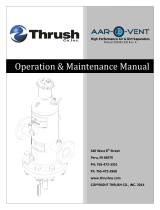
Clearances
Hot water pipes, vent pipes, and piping ends all have
a minimum clearance requirement from combustible
surfaces. There are also minimum allowable service
clearances and recommended service access
clearances. See Figure 1 for all clearances.
IMPORTANT
Without the recommended minimum clearances for
service access, it may not be possible to service the
boiler without removing it from the space.
Figure 1 Clearances for SVF Boilers
220089
Top
Top
Left
Side
Left
Side
Edge of opening within 12 inches of floor.
Edge of opening within 12 inches of floor.
Air openings
(when required)
Air openings
(when required)
Controls end
Front
Controls end
Front
Right
Side
Right
Side
Edge of opening within 12 inches of ceiling.
Edge of opening within 12 inches of ceiling.
Piping end
Piping end
Vent
pipe
Vent
pipe
Ensure that the installation complies with all state, local, and applicable codes.
Clearance from:
Minimum clearances to
combustible surfaces
(inches)
Minimum allowable service
clearances
(inches)
Recommended minimum service
access clearances
(inches)
SVF 1000 SVF 1500-3000 SVF 1000 SVF 1500-3000 SVF 1000 SVF 1500-3000
Controls end 0 0 30 30 35 35
Left side 0 0 0* 12* 24* 24*
Right side 0 0 0* 12* 24* 24*
Piping end 22 22 18** 22
35
(Measured from
frame, not pipes)
35
(Measured from
frame, not pipes)
Top 0 0 24*** 24*** 24*** 24***
Floor 0 0 — — — —
Vent pipe 3/16 3/16 — — — —
Hot water pipes 1/2 1/2 — — — —
* Boiler can be installed next to another boiler. Recommended clearances shown allow for easier service and maintenance.
** Minimum allowable service clearance to a non-combustible surface.
*** Top clearance allows for access to the cover plate for burner and heat exchanger service.

1000-3000
10 550-100-255/0823
1
2
3
4
5
6
7
8
Air Openings
Follow the National Fuel Gas Code ANSI Z223.1/
NFPA 54, latest edition for the U.S. Follow the
Natural Gas and Propane Installation Code CAN/CSA
B149.1 for Canada.
Follow all applicable codes to size and verify size
of the combustion and ventilation air openings into
the space.
The SVF boiler requires a special vent system.
See the Venting and Combustion Air sections starting
on page 29 for required air openings and sizing for
direct vent or direct exhaust installations.
SVF Boiler Alone in Boiler Room:
Direct Vent installations: No air ventilation openings
into boiler room are needed if the clearances around
the boiler are at least equal to the recommended
service clearances shown in Figure 1, page 9.
For spaces that do not supply the recommended
minimum service access clearances, see the direct
vent instructions for required openings for venting
starting on page 44.
Direct Exhaust installations: Provide air openings
as specied in the Direct Exhaust - Room Air
Openings section, starting on page 37.
SVF Boiler in a Room With Other Appliances:
Direct Vent installations: Size openings only on
the basis of the other appliances in the space. No
additional air opening free area is needed for the
SVF boiler because it takes its combustion air from
outside.
!
WARNING
For direct vent installations where the boiler is
located in the same room as other appliances,
provide combustion air openings correctly sized
for all appliances in the room EXCEPT the SVF
boiler. Failure to comply could result in severe
personal injury, death, or substantial property
damage.
Direct Exhaust installations: Combustion air
openings into the room must be sized to handle the
SVF boiler and all other appliances. See the direct
exhaust venting instructions starting on page 37 for
required openings.
The boiler control has the ability to operate a
combustion air damper. Refer to section D on page
67 and the SVF Advanced Manual (part number
550-100-292).
!
WARNING
In direct exhaust installations, the boiler
draws combustion air from the boiler. Provide
combustion air openings correctly sized for all
appliances in the room, INCLUDING the SVF
boiler. Failure to comply could result in severe
personal injury, death, or substantial property
damage.

1000-3000
11550-100-255/0823
1
2
3
4
5
6
7
8
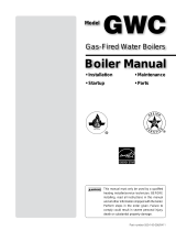
Preparing for Multiple Boilers
1. Provide the clearances shown in Figure 2 and
follow local codes. Other layouts can be used if
all required clearances are maintained.
2. Construct boiler foundation if the oor in the boiler
room is uneven or if there is the probability of
ooding. Size foundation to allow for clearance
and spacing dimensions shown in the gure
below.
3. Chalk-line boiler locations on foundation or boiler
room oor.
4. Remove boilers from the crate and assemble
according to instructions in this manual.
5. Provide clearance for installation of venting,
air piping, gas piping, condensate piping and
components, expansion tank, boiler pump, and
other accessories as given in Figure 1, page 9.
Figure 2 Side-to-side mounting of multiple boilers
18" (or as needed for piping or code requirements)
Minimum Allowable Service
220090
0” or 24"
(or as required
by codes)
0” or 24"
(or as required
by codes)
24"
(or as required
by codes)
Recommended set up
36" (or as required by codes)
18" minimum, 35” recommended (or as needed for piping or code requirements)
24"
(or as
required
by codes)
24"
(or as
required
by codes)
24"
(or as
required
by codes)
24"
(or as
required
by codes)
0”
(or as required
by codes)
0”
(or as required
by codes)

1000-3000
12 550-100-255/0823
1
2
3
4
5
6
7
8
Removing the Boiler from the Crate
Leave the boiler in the crate pallet until ready to
place in the nal location. Follow all uncrating
instructions. Refer to Figure 4 (SVF 1000) and Figure
5 (SVF 1500-3000) on page 13 for the following
instructions.
NOTICE
If the boiler has been stored in a location with
temperatures below 32°F (0°C), handle with care until
the plastic components come to room temperature.
NOTICE
Leave the plastic covers on the connections and
adapters until ready to attach piping. This will protect
the tting surfaces from damage and prevent debris
from entering the vent or air adapters.
1. Move the crate to a solid, level surface. The crate
must sit securely on the ground.
2. Ensure there is sucient clearance for the crate,
ramp, and nal boiler placement on the oor in
front of the piping.
!
WARNING
The boiler is heavy. Use caution not to drop
the boiler. Use proper lifting equipment and
techniques. Do not lift the boiler with water or gas
pipes. Do not handle, apply weight to, or push
on the gas pipes. Failure to comply could result
in severe personal injury, death, or substantial
property damage.
3. Remove the ramp from the crate. Place the end
of the ramp into the notch in the pallet as show in
the gures. Follow the uncrating instruction label
to secure the ramp to the pallet.
4. Remove the screws and lag bolts from the
shipping brackets.
Placing the Boiler
1. Roll the boiler down the ramp and move the boiler
into position. The boiler must be unloaded from
the pallet onto a solid, level surface.
!
WARNING
The boiler is heavy. Use caution when rolling
down the ramp. When moving the boiler, apply
pressure ONLY at the jacket corner posts or
water manifolds. Potential bodily injury or boiler
damage could be caused if handling the boiler
improperly.
2. All four casters are swivel type. Take care to keep
the boiler straight when rolling.
3. Adjust the leveling legs down until they are rmly
in contact with the oor. Remove the jacket
panels to access bolt heads and jam nuts for
leveling the boiler.
4. Continue adjusting the legs until the bottom of the
boiler base is .25"-.50" (6.35-12.70 mm) above
the oor while keeping the boiler level. Check
the level, front to back and side to side. Measure
level on the cover plate. See Figure 3.
CAUTION
!
Do not rest the boiler on the casters. The casters
are intended for moving the boiler into position
only. The support legs must be extended to take
the load o the boiler.
Installation is NOT complete until the leveling legs are
lowered below the wheels. The wheels MUST be lifted off
of the ground. Refer to manual for minimum distance
required.
550-225-451 (0522)
WARNING
LEVELING LEGS
Figure 3 Leveling legs warning

1000-3000
13550-100-255/0823
1
2
3
4
5
6
7
8
Figure 4 SVF 1000 boiler on pallet with ramp in position
220131
Ramp
Pallet
Apply pressure only to jacket
corners when moving
Shipping brackets
(front and back)
Notch
Hex head bolts
3/8" wrench
Lag bolts
7/16" socket or
wrench
230188
Ramp
Pallet
Apply pressure only to jacket
corners when moving
Notch
Hex head bolts
3/4" wrench
Lag bolts
9/16" socket or
wrench
Shipping brackets
(front and back)
Figure 5 SVF 1500-3000 boiler on pallet with ramp in position

1000-3000
14 550-100-255/0823
1
2
3
4
5
6
7
8
Seismic Bracket Installation – SVF 1000
For applications requiring bolting down of the SVF
1000 boiler (such as earthquake zone requirements),
use the leveling legs to position the boiler until
the bottom of the boiler base is at least .25" (6.35
mm) above the oor. Eight 3/8" bolts and four 5/8"
bolts are used to secure these two brackets to the
base. See Figure 6 for details. Refer to the seismic
calculations document for additional information.
!
WARNING
Follow all applicable codes and recognized
engineering design practices to verify the nal
mounting will meet all seismic, structural, and
other requirements. Failure to comply could
result in severe personal injury, death, or
substantial property damage.
Brackets (x2)
Brackets (x2)
Leveling
Legs (x6)
Leveling
Legs (x6)
Mount to the floor
in these locations
on each bracket
per the seismic
sheet (x4)
Mount to the floor
in these locations
on each bracket
per the seismic
sheet (x4)
5/8" bolts
(x2 each bracket)
3/8" bolts
(x4 each bracket)
220091
Figure 6 Seismic mounting brackets on the SVF 1000
boiler (provided by others)

1000-3000
15550-100-255/0823
1
2
3
4
5
6
7
8
Seismic Bracket Installation – SVF 1500-3000
For applications requiring bolting down of the boiler
(such as earthquake zone requirements), follow the
instructions below.
1. Use the leveling legs to position the boiler until
the bottom of the boiler base is at least .25" (6.35
mm) above the oor.
2. Remove the six caster wheels and caster support
blocks from the base of the unit by removing 24
5/16" bolts and nuts.
3. Lower the leveling legs to position the boiler base
on the oor.
4. Remove six leveling legs, bolts, and nuts from the
base of the unit.
5. Six 1/2" bolts are used to secure six brackets to
the base. See Figure 7 for details.
6. Refer to the seismic calculations document for
additional information.
!
WARNING
Follow all applicable codes and recognized
engineering design practices to verify the nal
mounting will meet all seismic, structural, and
other requirements. Failure to comply could
result in severe personal injury, death, or
substantial property damage.
Brackets
(x6)
Brackets
(x6)
Mount to
the floor
in these
locations
on each
bracket
per the
seismic
sheet
Mount to
the floor
in these
locations
on each
bracket
per the
seismic
sheet
1/2" bolts
(One each
bracket)
1/2" bolts
(One each
bracket)
230189
Figure 7 Seismic mounting brackets on the SVF 1500-
3000 boilers (provided by others)

1000-3000
16 550-100-255/0823
1
2
3
4
5
6
7
8
High Altitude Installations
For high altitude installations (over 2,000 ft.),
maximum blower, minimum blower, and ignition RPM
must be updated according to Table 15, page 113.
Pressure Test Preparation
Do not install the relief valve until pressure testing is
complete. See Relief Valve Installation on page 19
for installation instructions and warnings.
IMPORTANT
Apply pipe dope on all connections in the following
steps. Use pipe dope sparingly.
Reference Figure 8 for the following steps. All
components in this section are provided by the
installer except a 30psig relief valve and the P/T
gauge.
1. Remove the relief valve if it is installed.
2. On the boiler supply pipe, install two tees as
shown in Figure 8. Orient the tee closest to the
boiler up into a vertical position. Install the second
tee in a horizontal position.
a. The tee in the vertical position is where the
relief valve will be installed after the pressure
test. Install an NPT plug in this location for the
pressure test.
b. The tee in the horizontal position is where
the P/T gauge is installed for testing and for
normal boiler operation.
3. Install a shuto valve on the supply side and
connect it to the rest of the system piping.
4. Install a drain valve and a shuto valve on the
boiler return pipe before connecting to the rest
of the system piping. See Figure 8 for the boiler
drain location.
5. If the pressure test is conducted with a pressure
over 160 psig, remove the automatic air vent
located inside the boiler cabinet on the heat
exchanger port; replace it with a 1/2" NPT plug.
Boiler Drain
Boiler Drain
P/T Gauge
P/T Gauge
Relief Valve
(installed after testing)
Relief Valve
(installed after testing)
220132
Figure 8 Hydrostatic test piping connections - anges,
valves, and gaskets provided by installer

1000-3000
17550-100-255/0823
1
2
3
4
5
6
7
8
Fill the Boiler
1. Open the shuto valves installed on the supply
and return connections.
2. Allow water to ow into the bottom connection
and air to ow out the top connection.
3. When water reaches the shuto valve on top,
allow water to ow long enough to ensure all air is
out of the heat exchanger.
4. Close the shuto valves on supply and return lines.
5. Close o the water supply.
Hydrostatic Pressure Test
1. Use the hand pump to raise water pressure.
2. The test pressure should be 1.5 times the
pressure setting of the relief valve.
3. Gradually apply pressure until test pressure is
reached. Test pressures are shown in Table 4
and are compared to the normal operation of the
boiler with the relief valve installed.
4. Hold at test pressure for 10 minutes.
5. Maintain constant gauge pressure throughout the
test.
6. Check for leaks. Repair any leaks from threaded
joints. If leaks are found in the heat exchanger,
consult your WM Technologies representative.
7. Slowly release pressure and drain.
8. Install the automatic air vent if removed.
Pressure Test Precautions
!
WARNING
All air MUST be purged out of the heat
exchanger before performing the hydrostatic
pressure test.
The test pressure MUST NOT exceed the
maximum pressure on the P/T gauge. If the
test pressure is going to exceed the maximum
range of the current P/T gauge, use an
appropriate gauge for the test.
Leaks must be repaired immediately. Leaks
can damage the boiler, leading to substantial
property damage.
DO NOT leave the boiler unattended at any
time during testing. A cold water ll could
expand and cause excessive pressure,
resulting in severe personal injury, death, or
substantial property damage.
The release of high pressure water should be
done in a safe manner. Failure to release the
water safely could result in severe personal
injury, death, or substantial property damage.
DO NOT use petroleum-based cleaning or
sealing compounds in the boiler system.
Gaskets and seals in the system may be
damaged, resulting in substantial property
damage.
Table 4 Test pressure
Relief Valve Pressure Test Pressure
30 psig 45 psig
50 psig 75 psig
100 psig 150 psig
160 psig 240 psig

1000-3000
18 550-100-255/0823
1
2
3
4
5
6
7
8
General Piping Information
NOTICE
Use two wrenches when tightening water piping
at the boiler with one at the boiler interior piping to
prevent it from turning. Failure to prevent boiler piping
connections from turning could cause damage to
boiler components.
Additional controls, when required:
The control module uses temperature sensors to
provide both high limits protection and operating limit
control. The module is UL353 Limit Controls certied
to meet ASME CSD-1 and Section IV requirements.
A manual reset of the equipped low water cut-o is
performed through the control module. Some codes
and jurisdictions may require additional external
controls.
Operating limit set point =
Supply Max. Temperature + O Dierential
Additional limit controls:
• Consult local requirements for other codes and
standards to determine if additional limit devices
are needed.
• The control provides two sets of limit control
contacts. One set will cause automatic reset, while
the other will cause manual reset of the control.
See the Field Wiring section starting on page 57
for wiring information.
• The control can be reset using the manual RESET
function on the control display.
NOTICE
If the heating system includes circuits that require
lower temperature water and circuits that require
higher temperature water, it is recommended to
protect low-temperature circuits with limit controls
that are wired to a manual or automatic reset circuit
on the control.
Low water cut-o:
A push-to-test low water cuto is factory installed on
the switch panel on the left side of the control tray.
The low water cuto probe is mounted on the front of
the heat exchanger.
The low water cuto is manually reset through
the main control. This can be performed through the
display by selecting RESET LOCKOUT.
Backow preventer:
Use a backow check valve in the water ll as
required by local codes.
Pressure and Temperature Gauge
The boiler is shipped with a 1/4" NPT pressure and
temperature (P/T) gauge. The gauge has a pressure
range up to 75 psig. This gauge meets ASME
requirements for a relief valve setting of up to 50 psig.
The P/T gauge is mounted to a port on the heat
exchanger outlet pipe. See Figure 8, page 16 for
placement details.

1000-3000
19550-100-255/0823
1
2
3
4
5
6
7
8
Relief Valve Installation
!
WARNING
Do NOT install a relief valve with a pressure
higher than 160 psig. This is the maximum
allowable relief valve setting for the SVF boiler.
The boiler is shipped with a 30 psig relief valve.
!
WARNING
Improper installation of the relief valve and
discharge line can cause water damage and
scalding. Follow all instructions and guidelines
to avoid severe personal injury, death, or
substantial property damage.
1. A 30 psig relief valve is shipped with the boiler.
The valve must be installed by a qualied
installer. The valve should be connected as close
to the boiler water outlet as possible.
2. Connect discharge piping to a safe disposal
location according to the guidelines below.
• Discharge line must be connected to the relief
valve outlet and run to a safe place of disposal.
Terminate the discharge line in a manner that will
prevent the possibility of severe burns or property
damage should the valve discharge.
• Discharge line must be as short as possible and
be the same diameter as the valve discharge
connection throughout its entire length.
• Discharge line must pitch downward from the
valve and terminate at least 6" above the oor drain
where any discharge will be clearly visible.
• Discharge line shall terminate plain, not threaded,
with a material serviceable for temperatures of
375°F (191°C) or greater.
• Do not pipe the discharge to any place where
freezing could occur.
• Do not install any shuto valve between the relief
valve and boiler, or in the discharge line. Do not
plug or place any obstruction in the discharge line.
• After lling and pressurizing the system, test the
operation of the valve by lifting the lever. Make
sure the valve discharges freely. If the valve fails to
operate correctly, replace it with a new relief valve.
Air Inlet Adapter Installation (SVF 1000 only)
A 3-1 adapter with two cover plates are shipped with
the SVF 1000 boiler. These parts must be installed
on the boiler before air inlet piping. See Figure 10.
1. Place the 3-1 adapter over the studs on the air
intake box at the top of the boiler. Secure the
adapter with four M4 x 0.7 nuts using a 7 mm
socket.
2. Install the two cover plates over the adapter on
both sides with six 1/4"-20 screws using a T30 bit.
Figure 9 Relief valve location
220133
Relief Valve,
installed
Figure 10 Air inlet 3-1 adapter with cover plates
220153

1000-3000
20 550-100-255/0823
1
2
3
4
5
6
7
8
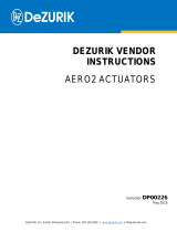
Pipe Sizing
Size the piping and the pumps to provide the required
temperature rise. See Figure 11 for boiler head loss
curves. See Table 6, page 21 for maximum and
minimum ow rate through the boiler and head loss
versus ow rate.
NOTICE
Pipe sizing should be based on the desired
temperature rise for the system, corresponding to the
recommended maximum ow rate. Failure to follow
these guidelines could result in system issues.
NOTICE
DO NOT design the piping and components for a
boiler ow rate above or below the ranges given in
Table 6, page 21 without using one of the piping
strategies listed below. Insucient ow will cause
nuisance outages due to limit operation. Excessive
ow can damage the boiler heat exchanger from
erosion.
Size system piping per Table 5, or apply recognized
engineering practices to size the piping.
IMPORTANT
The SVF 1000-3000 boilers have 3" ange
connections. Installer to provide reducers to adapt
from external piping to the boiler supply and return
connections if the system allows.
Higher ow rates than shown in Table 6, page 21:
• Use Primary/Secondary piping. See pages 24,
26, and 27.
• Add a dierential pressure bypass valve to
bypass the excessive ow in a Variable/Primary
ow system, or provide an alternative engineering
solution. See the gures on page 25.
Lower ow rates than shown in Table 6, page 21:
• Use Primary/Secondary piping.
• In a Variable/Primary ow system, it is
recommended to install a ow switch that is set at
the minimum ow rate of the boiler. The variable
circulator will increase water ow and prevent the
boiler from ring with an insucient ow rate. The
higher water ow will make the ow switch contact,
which will start the boiler.
Sch 40 Pipe
Diameter
Maximum
Flow Rate
GPM
SCH 40 Pipe
Diameter
Maximum
Flow Rate
GPM
2 45 6 800
3 140 8 1650
4 290 10 3000
5 500 12 4750
Figure 11 Pressure drop versus ow rate for SVF boilers
Table 5 Recommended pipe sizing per ow rate
230035
Page is loading ...
Page is loading ...
Page is loading ...
Page is loading ...
Page is loading ...
Page is loading ...
Page is loading ...
Page is loading ...
Page is loading ...
Page is loading ...
Page is loading ...
Page is loading ...
Page is loading ...
Page is loading ...
Page is loading ...
Page is loading ...
Page is loading ...
Page is loading ...
Page is loading ...
Page is loading ...
Page is loading ...
Page is loading ...
Page is loading ...
Page is loading ...
Page is loading ...
Page is loading ...
Page is loading ...
Page is loading ...
Page is loading ...
Page is loading ...
Page is loading ...
Page is loading ...
Page is loading ...
Page is loading ...
Page is loading ...
Page is loading ...
Page is loading ...
Page is loading ...
Page is loading ...
Page is loading ...
Page is loading ...
Page is loading ...
Page is loading ...
Page is loading ...
Page is loading ...
Page is loading ...
Page is loading ...
Page is loading ...
Page is loading ...
Page is loading ...
Page is loading ...
Page is loading ...
Page is loading ...
Page is loading ...
Page is loading ...
Page is loading ...
Page is loading ...
Page is loading ...
Page is loading ...
Page is loading ...
Page is loading ...
Page is loading ...
Page is loading ...
Page is loading ...
Page is loading ...
Page is loading ...
Page is loading ...
Page is loading ...
Page is loading ...
Page is loading ...
Page is loading ...
Page is loading ...
Page is loading ...
Page is loading ...
Page is loading ...
Page is loading ...
Page is loading ...
Page is loading ...
Page is loading ...
Page is loading ...
Page is loading ...
Page is loading ...
Page is loading ...
Page is loading ...
Page is loading ...
Page is loading ...
Page is loading ...
Page is loading ...
Page is loading ...
Page is loading ...
Page is loading ...
Page is loading ...
Page is loading ...
Page is loading ...
Page is loading ...
Page is loading ...
Page is loading ...
Page is loading ...
Page is loading ...
Page is loading ...
Page is loading ...
Page is loading ...
Page is loading ...
Page is loading ...
Page is loading ...
Page is loading ...
Page is loading ...
Page is loading ...
Page is loading ...
Page is loading ...
Page is loading ...
Page is loading ...
Page is loading ...
Page is loading ...
Page is loading ...
Page is loading ...
Page is loading ...
Page is loading ...
Page is loading ...
Page is loading ...
Page is loading ...
Page is loading ...
Page is loading ...
Page is loading ...
-
 1
1
-
 2
2
-
 3
3
-
 4
4
-
 5
5
-
 6
6
-
 7
7
-
 8
8
-
 9
9
-
 10
10
-
 11
11
-
 12
12
-
 13
13
-
 14
14
-
 15
15
-
 16
16
-
 17
17
-
 18
18
-
 19
19
-
 20
20
-
 21
21
-
 22
22
-
 23
23
-
 24
24
-
 25
25
-
 26
26
-
 27
27
-
 28
28
-
 29
29
-
 30
30
-
 31
31
-
 32
32
-
 33
33
-
 34
34
-
 35
35
-
 36
36
-
 37
37
-
 38
38
-
 39
39
-
 40
40
-
 41
41
-
 42
42
-
 43
43
-
 44
44
-
 45
45
-
 46
46
-
 47
47
-
 48
48
-
 49
49
-
 50
50
-
 51
51
-
 52
52
-
 53
53
-
 54
54
-
 55
55
-
 56
56
-
 57
57
-
 58
58
-
 59
59
-
 60
60
-
 61
61
-
 62
62
-
 63
63
-
 64
64
-
 65
65
-
 66
66
-
 67
67
-
 68
68
-
 69
69
-
 70
70
-
 71
71
-
 72
72
-
 73
73
-
 74
74
-
 75
75
-
 76
76
-
 77
77
-
 78
78
-
 79
79
-
 80
80
-
 81
81
-
 82
82
-
 83
83
-
 84
84
-
 85
85
-
 86
86
-
 87
87
-
 88
88
-
 89
89
-
 90
90
-
 91
91
-
 92
92
-
 93
93
-
 94
94
-
 95
95
-
 96
96
-
 97
97
-
 98
98
-
 99
99
-
 100
100
-
 101
101
-
 102
102
-
 103
103
-
 104
104
-
 105
105
-
 106
106
-
 107
107
-
 108
108
-
 109
109
-
 110
110
-
 111
111
-
 112
112
-
 113
113
-
 114
114
-
 115
115
-
 116
116
-
 117
117
-
 118
118
-
 119
119
-
 120
120
-
 121
121
-
 122
122
-
 123
123
-
 124
124
-
 125
125
-
 126
126
-
 127
127
-
 128
128
-
 129
129
-
 130
130
-
 131
131
-
 132
132
-
 133
133
-
 134
134
-
 135
135
-
 136
136
-
 137
137
-
 138
138
-
 139
139
-
 140
140
-
 141
141
-
 142
142
-
 143
143
-
 144
144


Weil-McLain SVF Stainless Vertical Firetube (1000 MBH) User manual
- Category
- Water heaters & boilers
- Type
- User manual
Ask a question and I''ll find the answer in the document
Finding information in a document is now easier with AI
Related papers
-
Weil-McLain SVF Stainless Vertical Firetube (1500–3000 MBH) User manual
-
-
Weil-McLain SVF 750 User manual
-
-
-
-
-
Weil-McLain 384000003 User manual
-
-
Other documents
-
-
Rheem RHBH-L120i Operating instructions
-
Viessmann Vitocrossal User manual
-
Wolf CGB-75 Installation And Technical Manual
-
 AIR SYSTEMS SVF-8AC Operating instructions
-
 Thrush TBSF-030-W Operating & Maintenance Manual
-
Emerson 24000CVF/SVF User manual
-
Lochinvar CREST 2.5 User manual
-
 Williamson-Thermoflo GWC-070 User manual
-
 DeZurik ACT COMPAK (AERO2) Operating instructions


