Page is loading ...

Models 725/850
Commercial Condensing
Gas-Fired Water Boilers
Application Guide
for
Common Venting SVF Boilers
Manual Part Number 550-100-296/0123
Common Venting methods and requirements for SVF Boilers (SVF 725/850)
The SVF boiler can be common vented when the following requirements are met.
• Common venting of the SVF boiler can only be done in a Category II vent system. All requirements for
the SVF boiler to be vented in a Category II conguration must be met as stated in the SVF Boiler Manual
or all subsequent addenda.
• SVF boilers can only be common vented with other SVF Boilers.
• The maximum number of SVF boilers to be common vented together is four.
• The Vent system for a Category II SVF boiler is considered a Designed / Engineered vent system and
should be designed by a professional using accepted engineering practices.
• Vertical Vent only.
• Combustion air must come from the boiler room. See Direct Exhaust – Room Air Openings requirements
in the SVF Boiler Manual.
• Must increase venting to 8” using a 6” to 8” bell reducer at boiler vent adapter for Category II Vent Connection.
(continued on the next page)
Hazard Denitions
The following dened terms are used throughout these Instructions to bring attention to the presence of
hazards of various risk levels or to important information concerning the life of the product.
!
WARNING
Warning indicates the presence of hazards that can result in severe personal injury, death, or
substantial property damage.
IMPORTANT
Important indicates additional information that is important, but is not related to personal injury or property damage.

svf gas-fired water boiler — application guide
2 550-100-296/0123
Common Venting methods and requirements for SVF Boilers (SVF 725/850), continued
• The Vent System should be designed so that the pressure in the vertical 8” vent pipe immediately
following the bell reducer is between the ranges provided in Table 1, during all operating conditions
(i.e., High Fire through Low Fire, prepurge, post purge and ignition). If a negative pressure cannot be
guaranteed at prepurge and post purge, a backow preventer is required on each boiler’s vent.
!
WARNING
To prevent backow through boiler, negative pressure must be maintained in vent system at all times
including prepurge and post purge cycles. Failure to comply can result in severe personal injury,
death, or substantial property damage.
• Flue gas temperature should not exceed 210°F; the boiler will shut down and recycle if it does. The ue
gas temperature should typically be within 20°F of the return water temperature of the boiler. If there is
the potential for a wide variation in return water temperatures, the lowest possible temperature should be
used for any calculations.
• Stack / Vent Flow Rate for each individual boiler model is listed in Table 1. This ow rate is based on the
unit running at 9.25% CO2 (natural gas), and the maximum ue gas temperature of 210°F.
The values can vary depending on the location of the installation and operating conditions.
• A carbon monoxide detector(s) is required in the boiler room for SVF boilers installed in a Category II
conguration. The carbon monoxide detector must be wired on the same electrical circuit as the boiler.
Check your local codes for any additional requirements of carbon monoxide detectors.
!
WARNING
Improper Installation of a Category II vent system resulting in positive pressure in the vent system can
cause ue gas spillage and carbon monoxide emissions, which can result in severe personal injury or
death.
IMPORTANT
Weil-McLain recommends the use of a Variable Speed Chimney Fan or Power Venter to ensure that the
appropriate negative pressure is maintained for Category II venting. As a result of the boiler’s eciency, the
exhaust gas temperatures can be low resulting in less natural draft. A ow proving switch should be wired into
the Proof of Closure jumper circuit on the boiler control. See the boiler manual for additional information.
IMPORTANT
Weil-McLain recommends the use of a Double Acting Barometric Damper or Modulating Damper to ensure the
appropriate negative pressure range is kept for Category II venting.
IMPORTANT
When using a damper of any kind, it is recommended to use a thermal spill switch to detect any exhaust ow
into the boiler room. Verify the temperature range on the thermal spill switch is adequate for the Flue gas
temperature from the SVF boiler. The use and set-point of this shall be determined by the system designer.
The Auto reset input on the Boiler’s control can be used to wire in the thermal spill switch.
Boiler Model Input
Btuh
Stack / Vent
ow rate
(scfm)
Negative pressure to be
maintained at the vent connection
of the boiler
(inches w.c.)
SVF vent adapter required
for Category II
SVF 725 725,000 149 -0.001 to -0.100 8"
SVF 850 850,000 175 -0.001 to -0.100 8"
Table 1 Rating and vent data

svf gas-fired water boiler — application guide
3550-100-296/0123
IMPORTANT
The thermal spill switch should shut down all boilers connected to the common ue. Each boiler must be wired
to its own set of dry contacts activated by the spill switch.
IMPORTANT
Increasing the negative pressure in the vent pipe will slightly increase the ring rate at low re, thus reducing
the boiler’s true modulation range. Consider this factor during system design.
Code Compliance
!
WARNING
Provisions for combustion and ventilation air must be made in accordance with the codes listed below.
Failure to comply can result in severe injury, death, or substantial property damage.
Installations must provide provisions for combustion and ventilation air in accordance with the section “Venting
of Equipment”, of the National Fuel Gas Code, ANSI Z223.1 / NFPA 54, or “Venting Systems and Air Supply for
appliances” of the Natural Gas and Propane Installation Code, CAN/CSA B149.1, or applicable provisions of
the local building codes.
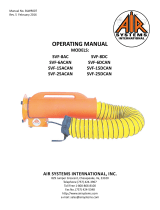
The gure below represents a general common venting approach. The Vent system for a Category II SVF
boiler is considered a designed engineered vent system and should be designed by a professional using
accepted engineering practices.
220296
*Double Acting
Barometric Damper
(by others if needed)
*
Horizontal Length
(by others)
Flue Vent
Flue Vent
* Thermal
Spill Switch
(by others if needed)
*
(Based on engineered vent system determined by others)
Common venting of SVF boilers requires
a negative flue pressure to be maintained
by an engineered vent system throughout
its operation. See Table 1, page 2 for
acceptable pressures.
Common venting of
SVF boilers requires
Direct-Exhaust
*Vent Diameter
(by others)
*
Vertical Height
(by others)
* Variable Speed
Vent Inducer
(by others if needed)
Minimum
3’ of 8” pipe
8” to 6”
bell reducer
Vent slope and condensate
drains according to vent
manufacturers instructions.
45°
Connection
Air
Vent Vent
Air
Vent
Air
Backflow Preventer
(as needed)
per Para. 1
4'6" to 6'
Figure 1 Common vent

Manual Part Number 550-100-296/0123
WM Technologies, LLC
500 Blaine Street
Michigan City, IN 46360-2388
T
elephone: (800) 654-2109
weil-mclain.com
/