Chloride 55 Series Contemporary Die Cast Aluminum Exit Install Instructions
- Type
- Install Instructions
This manual is also suitable for
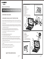
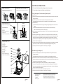
Chloride 55 Series Contemporary Die Cast Aluminum Exit: This versatile emergency lighting solution offers reliable illumination during power outages and other emergencies. It features dual voltage operation (120-277 VAC), self-powered battery backup, and a rugged die-cast aluminum housing for durability. Suitable for both indoor and outdoor use, this exit sign can be ceiling or side mounted, providing clear visibility from all angles.
Chloride 55 Series Contemporary Die Cast Aluminum Exit: This versatile emergency lighting solution offers reliable illumination during power outages and other emergencies. It features dual voltage operation (120-277 VAC), self-powered battery backup, and a rugged die-cast aluminum housing for durability. Suitable for both indoor and outdoor use, this exit sign can be ceiling or side mounted, providing clear visibility from all angles.


-
 1
1
-
 2
2


Chloride 55 Series Contemporary Die Cast Aluminum Exit Install Instructions
- Type
- Install Instructions
- This manual is also suitable for
Chloride 55 Series Contemporary Die Cast Aluminum Exit: This versatile emergency lighting solution offers reliable illumination during power outages and other emergencies. It features dual voltage operation (120-277 VAC), self-powered battery backup, and a rugged die-cast aluminum housing for durability. Suitable for both indoor and outdoor use, this exit sign can be ceiling or side mounted, providing clear visibility from all angles.
Ask a question and I''ll find the answer in the document
Finding information in a document is now easier with AI
Related papers
Other documents
-
 BARRON QXT Series Thin Thermoplastic Exit Installation guide
-
RAB Lighting EXIT34-RG Operating instructions
-
Lithonia Lighting ECC G M6 Installation guide
-
 BARRON QCRT Series Thin Thermoplastic Combo Installation guide
-
GE current IND622 User manual
-
GE current IND623 User manual
-
 BARRON NY900U NYC Edge-lit Series Installation guide
-
e-conolight KXTE Die-Cast LED Exit Sign User manual
-
 BARRON VLEDC Tempo Pro Thermoplastic Series Installation guide
-
 BARRON S900C Series LED Edge-lit Combo Exit Sign Installation guide


