Page is loading ...

PM1730 Issue 1 (July 2019)
Studio 3
Inset Convector Cassette
IMPORTANT
THE OUTER CASING, FRONT AND GLASS PANEL BECOME EXTREMELY HOT DURING
OPERATION AND WILL RESULT IN SERIOUS INJURY AND BURNS IF TOUCHED. IT
IS THEREFORE RECOMMENDED THAT A FIREGUARD COMPLYING WITH BS 8423
(LATEST EDITION) IS USED IN THE PRESENCE OF YOUNG CHILDREN, THE ELDERLY
OR INFIRM.
Do not attempt to burn rubbish in this appliance. Please read these Instructions carefully before
installation or use.
Keep them in a safe place for future reference and when servicing the fire.
The commissioning sheet found on page 3 of these instructions should be completed by the Installer.
Instructions for Use, Installation & Servicing
For use in GB & IE (Great Britain & Republic of Ireland).

2
Covering the following models:
RVST-3HT
Studio Cassette - Inset Convector
Contents
DESIGN PROTECTION
The Studio design, including it's frames and accessories, are
protected by European Design Registration
No. 001169338 0002 0008.
Appliance Commissioning Checklist ......................3
User Instructions .......................................................4
Getting Started ...........................................................................4
User Instructions ........................................................................6
Care & Maintenance...................................................................8
Troubleshooting ......................................................10
Installation Instructions ..........................................12
Installation Checklist ................................................................. 12
Pre-Installation Instructions ...................................................... 15
Installing the Appliance............................................................. 17
Commissioning ......................................................................... 29
Maintenance & Servicing ........................................31
Technical Appendix .................................................33
Information Requirement - Solid Fuel ..................................... 37
Spare Parts List ........................................................................38
Service Records ....................................................................... 39
If you have purchased your stove or fire from an authorised stockist
within our Expert Retailer Network, then automatically your product will
carry a 2 year warranty as standard. The 2 year warranty can be further
extended to a total warranty period of 5 years by registering your Stovax
Stove or Fireplace within one month of the latter of the purchase date
or installation date. Accordingly, the start date for the warranty period is
the date of purchase. During the registration process, the Expert Retailer
details will be required for your Extended Warranty to be activated. Any
product purchased outside of our Expert Retailer Network will carry a
standard 12 month, non-extendable warranty.
It is a condition of the Extended Warranty that the installation complies
with the relevant Building Regulations and is carried out by a suitably
trained and qualified individual (HETAS in the UK or equivalent in other
countries) with the certificate of installation and the Commissioning
Report on Page 3 completed and retained by the end user.
Full terms and conditions are detailed in the Warranty Statement on
the Stovax website www.stovax.com. In the event of any conflict of
information the wording on the website shall prevail.
Important Note: Should any problems be experienced with your
product, claims must first be submitted to the Expert Retailer where
the appliance was purchased from who will offer immediate assistance
or contact Stovax on your behalf.

3
Dealer appliance was purchased from:
Name:
Address:
Telephone number:
Essential information - MUST be completed:
Date Installed:
Model Description:
Serial Number:
Installation Engineer:
Company Name:
Address:
Telephone number:
Commissioning Checks - to be completed and signed:
Is flue system correct for the appliance:
YES NO
Flue swept and soundness test complete:
YES NO
Smoke test completed on installed appliance YES NO
Spillage test completed YES NO
Use of appliance and operation of controls explained YES NO
Clearance to combustible materials checked YES NO
Instruction book handed to customer YES NO
CO Alarm Fitted YES NO
Signature: ............................................................................ Print Name: ..........................................................................
To assist us in any guarantee claim please complete the following information:-
Appliance Commissioning Checklist

4
Welcome
Congratulations on purchasing your Stovax Studio, if
installed correctly Stovax hope it will give you many years of
warmth and pleasure for which it was designed.
The purpose of this manual is to familiarise you with your
stove, and give guidelines for its installation, operation and
maintenance. If, after reading, you need further information,
please do not hesitate to contact your Stovax retailer.
1. General Points
1.1 Before installation and/or use of this appliance please read
these instructions fully and carefully to ensure that you have
fully understood their requirements.
The appliance must be fitted by a registered installer*,
or approved by your local building control officer.
1.2 All local regulations, including those referring to national
and European Standards need to be complied with when
installing the appliance.
1.3 Only use for domestic heating in accordance with these
operating instructions.
1.4 You must burn only approved fuels. Do not use with liquid
fuels or as an incinerator.
1.5 Appliance surfaces become very hot when in use. Use
a suitable fireguard
‡
if young children, elderly or infirm
persons are present.
Stovax offer firescreens, sparkguards and hearthgate
systems for protection. Your Stovax dealer can advise you
about these products.
1.6 Donotplacephotographs,TV’s,paintings,porcelainor
other combustible items on the wall or near the appliance.
Exposure to hot temperatures will cause damage. Do not
place furniture or other items such as drying clothing closer
than 1m from the front of this appliance.
WARNING: Extra fuel should not be stored on or next to the
appliance. Only keep enough fuel for immediate use nearby
and never leave the appliance unattended for long periods
with any combustible material in close proximity.
1.7 Extractor fans or cooker hoods must not be placed in the
same room or space as this can cause appliance to emit
fumes into the room.
1.8 Do not obstruct inside or outside ventilation required for the
safe use of this appliance.
1.9 Do not make unauthorised changes to the appliance.
1.10 The chimney must be swept at least once a year.
See Section 12.
1.11 Do not onnect, or share, the same flue or chimney system
with another appliance.
SERIAL NUMBER
1.12 This number is required when ordering spare parts or
making warranty claims.
It is found on the appliance data plate, see Diagram 1.
1
Data Plate
Studio 3 Data plate only
accessible when door is closed
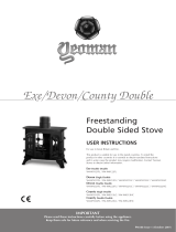
Triple Air Systems
Several Stovax appliances have triple air systems providing
cleaner burning, and greater efficiency and control,
See Diagram 2
1) Airwash - air drawn over the window cleans the glass.
The source of Primary Combustion air when burning wood.
2) Primary Air - for use initially when establishing fires.
3) Secondary Air - Secondary air is preheated through
a heat exchanger to combust unburned hydrocarbons,
providing a cleaner and more efficient burn.
1
3
2
2
Getting Started
‡In the U.K. these products must conform to the
latest edition of BS 8423, Fireguards for use with
solid fuel appliances.
If appliance is operating unattended they must
conform to the latest edition of BS 3248
*Registered on the Competent Persons Scheme
(GB only see page 36/ INFO (Republic of Ireland).

5
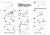
Airwash and Primary Air Controls
IMPORTANT: Stovax provide gauntlet style gloves
for the users protection from heat and any sharp
edges when using the appliance.
For your safety ensure that gloves are always
worn when opening, operating, refuelling or
handling internal metalwork.
1.13 Use a protective gloved hand to operate.
DO NOT OPERATE THE AIR CONTROLS WITH BARE HANDS
Airwash Control
Secondary
Air Inlet -
Factory Set
Primary Control
3
NOTE: The travel of the Airwash control and
Primary control may be limited if the appliance has
been set up to operate in a Smoke Control Area.
DOOR HANDLE
DO NOT OPEN THE DOOR WITH BARE HANDS
DO NOT OPEN THE DOORS WHEN THE FIREBOX IS
FULL OF FLAMES - WAIT FOR THEM TO DIE DOWN.
1.14 Engage tool in door as shown, see Diagram 4.
Pull door out and down to open.
Operating
tool
4
WARNING
Properly installed, operated and maintained this
appliance will not emit fumes into the room but
occasional fumes from de-ashing and refuelling
may occur.
Persistent fume emission is potentially
dangerous and must not be tolerated.
If fume emission persists:
• Open doors and windows to ventilate the room.
• Leave the room.
• Allow fire to burn out or safely dispose of fuel
from the appliance.
• Check for chimney blockage and clean if
required.
• Do not attempt to relight until the cause of the
emission has been identified and corrected.
• If necessary seek expert advice.
• All open flued appliances can be affected by
temporary atmospheric conditions which may
allow fumes to enter the house. Because of
this an electronic carbon monoxide detector
conforming to the latest edition of BSEN50292
must be fitted in the same room as the
appliance. The existence of an alarm must not
be considered a substitute for ensuring regular
servicing and maintenance of the appliance and
chimney system.
IF THE ALARM SOUNDS FOLLOW THE
INSTRUCTIONS GIVEN ABOVE.
Getting Started

6
2. Using the Appliance for the First Time
2.1 To allow the appliance to settle, and fixing glues and paint
to fully cure, operate the appliance at a low temperature for
first few days.
2.2 Do not touch the paint during the first period of use.
2.3 During this time the appliance may give off some unpleasant
odours. Keep the room well ventilated to avoid a build-up of
fumes.
2.4 Please be aware that, during use, rope seals may discolour.
This is normal.
3. Recommended Fuels
3.1 Wood Logs:
Burn only seasoned timber with a moisture content of less
than 20%. To ensure this allow cut wood to dry for 12 to 18
months.
Wood Length
Appliance Wood Length
Studio 3 250mm - 500mm
5
Poor quality timber:
— Causes low combustion efficiency
— Produces harmful condensation
— Reduces effectiveness of the airwash and life of
the appliance
Do not burn construction timber, painted, impregnated
/ treated wood, manufactured board products or pallet
wood.
3.2 Fuel consumption.
As tested at nominal heat output to the requirements of EN
13229: 2001 for intermittent operation:
Description
Fuel Consumption
Kg/hour
Wood
Studio 3 3.6
A number of factors can affect the performance of the
appliance. See Troubleshooting Section for details.
Fuel Overloading
The maximum amount of fuel specified in this manual
should not be exceeded, overloading can cause excess
smoke.
4. Lighting the Appliance
IMPORTANT: Stovax provide gauntlet style
gloves for the users protection from heat and any
sharp edges when using the appliance.
For your safety ensure that gloves are always
worn when opening, operating, refuelling or
handling internal metalwork.
4.1 For best results set air controls as shown, see Diagram 7.
Air Wash: Fully Open
Primary Air: Fully Open
7
4.2 Place firelighters or paper and dry kindling wood on the
base bricks.
A successful fire initially requires plenty of kindling to
establish a hot firebox and warm the chimney to aid flue
performance.
4.3 Light the paper or firelighters, see Diagram 6.
4.4 Leave the door slightly open as the fire establishes and
the glass warms to avoid build up of condensation.
6
4.5 Add larger pieces of wood.
Do not use full sized logs at this stage, build up gradually in
size. Too many logs may smother the fire.
Fuel Loading:
These are wide appliances and the logs should be laid out
in a single layer with gaps between, see Diagram 9.
Do not stack the logs on top of each other as this could
effect the efficiency.
DO NOT OVERLOAD THE APPLIANCE AS THE HEAT
OUTPUT WILL BE TOO HIGH.
User Instructions

7
5.3 When in use, burning the appliance at a high temperature
for a short period reduces tars and creosotes.
WARNING: DO NOT OPERATE THE APPLIANCE WITH
THE PRIMARY AIR CONTROL OPEN FOR LONG
PERIODS OF TIME AS THIS COULD CAUSE OVER-
FIRING AND MAY CAUSE PERMANENT DAMAGE.
Experience establishes settings to suit personal preference.
Refuelling
5.4 Open the Primary Air and Airwash controls fully.
Rake the embers evenly over the firebed to establish a
glowing firebed. If the firebed is low add a small amount
of kindling wood to help re-establish the fire.
5.5 Do not refuel when a large amount of flames are in the
firebox as this could cause smoke or flames to spill
into the room.
5.6 Close the doors immediately after refuelling.
These are wide appliances and the logs should be laid out
in a single layer with gaps between, see Diagram 7.
Do not stack the logs on top of each other as this could
effect the efficiency.
DO NOT OVERLOAD THE APPLIANCE AS TOO MUCH
FUEL COULD CAUSE IT TO OVER-FIRE.
5.7 After refuelling:
Burn the new logs at high output for a few minutes
before closing the Primary Air control. Adjust the burn
rate using the Airwash control.
Do not close the air controls until the fire is burning
well.
5.8 Do not burn large amounts of fuel with the Airwash
control closed for long periods of time. This reduces the
glass cleaning effect, causes tars and creosotes to build-up
in the appliance and flue system and will produce excessive
amounts of smoke.
5.9 When running the appliance refuel little and often for
clean, efficient burning.
A bright and clean firebox indicates the appliance is
burning well.
5.10 Do not burn continuously with the door open.
Shut Down
5.11 If there is still burning fuel in the firebox, Stovax do not
recommend shutting down the air controls completely
unless there is a chimney fire in progress (see Section 9
for advice). Closing the controls during the burning process
will cause poor combustion and could lead to a build up of
gasses that could ignite dangerously.
5.12 Always have enough air entering the stove to maintain some
flame within the firebox.
5.13 If it is necessary to shut down the appliance then run on a
high setting until all of the fuel has been burnt before closing
the air controls.
Be sure to use split logs and not whole pieces of wood.
Too much fuel in the firebox will cause the appliance to
reach higher temperatures than intended.
This can damage the interior components of the fire.
Suggested Loads:
4/5 logs no bigger than 5" (127mm) diameter
7
4.6 Close the door and follow the instructions for Running the
Appliance.
Do not run with the door slightly open except for initial
lighting as this could cause over-firing and damage the
appliance.
WARNING: DO NOT OPERATE THE APPLIANCE WITH
THE PRIMARY AIR CONTROL OPEN FOR LONG
PERIODS OF TIME AS THIS COULD CAUSE OVER-
FIRING AND MAY CAUSE PERMANENT DAMAGE.
5. Running the Appliance
Burning Wood
5.1 Close the Primary air control and use the Airwash
to control the burn rate when appliance is at operating
temperature, see Diagram 8.
Air Wash: Adjust Burn Rate
Primary Air: Close
Min
Max
8
Wood burns best on a bed of ash (approx. 25mm (1") deep).
5.2 Do not burn large amounts of fuel with the Airwash
Control closed for long periods of time. This reduces the
glass cleaning effect of the Airwash and causes tars and
creosotes to build-up in the appliance and flue system.
User Instructions

8
c) It is repaired as required before re-use. Use only
genuine Stovax replacement parts to keep your appliance in
safe, efficient working order.
10. General Cleaning
10.1 Clean and inspect the appliance regularly, especially in
periods of heavy use. Regular cleaning and maintenance
will help give many years of safe use.
10.2 Allow appliance to cool thoroughly to avoid risk of
burns.
10.3 Clean regularly, according to level of use.
10.4 Remove the ash completely
(see User Instructions, Section 7).
10.5 Check internal components for damage - grates, bricks,
baffles - and for obvious build up of soot, ash or debris
above the flue baffle(s) (these can be found in the upper
part of the firebox). Use a torch if necessary.
10.6 If there are any signs of a build up of debris above the flue
baffle(s) either:
— Arrange for the chimney to be swept (see User
Instructions, Section 12).
— Remove the baffles and clear the debris
(see Pre-Installation Sections).
10.7 Torefreshpaintednishesatouchupsprayisavailable.
Contact your Stovax retailer quoting the serial number found
on the appliance data badge.
Do not use aerosol sprays near an operating appliance.
11 Cleaning Glass
11.1 Keep the glass clean with correct use of the Airwash system
and good quality fuel.
11.2 Sometimes additional cleaning may be required.
Before undertaking this operation allow appliance to cool
fully. Do not clean hot glass.
11.3 On appliances with printed glass do not use cleaning
agents that have a high alkaline or acidic content, for
example Stovax Gel Cleaner, these are aggressive
cleaning agents designed to be used with heavily
stained clear glass. On printed glass surfaces, use
Stovax Glass Cleaner (Stovax No.4103) which is better
formulated for this application.
11.4 Before applying a cleaning agent remove any dust and
loose soot with a damp cloth.
11.5 Use an appropriate glass cleaner. Apply the cleaning fluid to
a cloth before rubbing onto the glass.
Apply carefully and do not apply excessively. Try to prevent
any run off which could soak into the rope seals around the
edge of the glass.
Soot can also contain acidic particles that can cause
corrosive damage to printed glass.
6. Extended Burning
6.1 It is possible to get the appliance to burn for extended
periods of time. In order to do this:
—De-ashpriortonalrefuelling.
— Burn new fuel at a high temperature for a few minutes
before closing the Primary Air Control.
— Set Airwash to low combustion settings.
This will gradually blacken the glass but it will clear when
operated at a high temperature for a short period.
7. Ash Removal
7.1 Wood burns best on a bed of ash
Do not allow ash to build up in the appliance as it will
not burn properly and may cause damage.
7.2 Open door, see Diagrams 4&5 on page 5.
Remove ash with a small shovel (available from Stovax).
Take care not to damage the ceramic lining of the appliance.
Do not use sharp pointed pokers.
7.3 Remove ash carefully - heat can remain long after use.
7.4 Carefully place the ash into a Stovax Ash Caddy (Stovax
Part No. 4227).
7.5 Do not place hot ash in a container made from plastic
or any other combustible material.
8. Over-Firing
8.1 Do not over-fill with fuel or run at high temperatures for long
periods or over-firing can occur.
DO NOT OPERATE THE APPLIANCE WITH THE
PRIMARY AIR CONTROL OPEN FOR LONG PERIODS
OF TIME AS THIS COULD CAUSE OVER-FIRING AND
MAY CAUSE PERMANENT DAMAGE.
8.2 Over-firing can cause permanent damage to the
appliance and invalid the product warranty.
9. Chimney Fire
9.1 If a chimney fire occurs:
— Shut all air controls immediately.
— Evacuate the building.
— Call the fire brigade.
— Do not re-enter the building until it is confirmed safe.
9.2 Do not use the appliance after a chimney fire until:
a) It has been inspected by a registered installer*,
confirming the appliance is safe to use.
b) The chimney system has been inspected and swept by a
chimney sweep, confirming the system is structurally sound
and free from obstruction*.
Care & Maintenance

9
Care & Maintenance
*Registered on the Competent Persons Scheme (GB
only) see page 36/ INFO (Republic of Ireland).
11.6 Remove dirt with a moist cloth and buff dry.
11.7 Some types of wood can cause a white residue to form
on the glass.
If this occurs it should be cleaned off at least once a
week during periods of heavy usage.
If the liquid cleaning agents recommended do not
remove this residue Stovax offer a dry cleaning pad
which will help remove heavy stains.
11.8 Before relighting the appliance ensure the glass is fully dried.
If the rope seal has absorbed excess cleaning agent it
is advisable to replace the rope as soon as possible to
preserve the printed finish of the glass.
12. Chimney Sweeping
12.1 To maintain safe and efficient use of the appliance, the
chimney/flue must be inspected and swept at least once a
year by a qualified chimney sweep*.
If the appliance is used continuously throughout the year,
or it is used to burn wood, more frequent sweeping is
recommended.
The best time to have the chimney swept is at the start of
the heating season.
12.2 The chimney, any connecting flue pipe and the appliance
flue ways, if incorporated, must be regularly cleaned.
12.3 Ensure adequate access for cleaning where it is not
possible to sweep through the chimney.
12.4 If the chimney is believed to have previously served an open
fire it must be swept a second time within a month of regular
use after installation.
13. Care Of Stove
Stovax has a range of cleaning and maintenance products
and accessories to keep your appliance in good working
order. Your Stovax retailer can advise you on suitable items
for your stove and provide genuine spare parts such as
replacementglass,doorsealingropeandrebricks.View
the extensive range at www.stovax.com by clicking on
Accessories. In addition, an annual service by a competent
engineer is recommended to keep your stove in the best
possible condition.
14. Seasonal Use
14.1 Clean and service the appliance if not used during the
warmer months, as detailed in the Maintenance and
Servicing section.
14.2 Set the air controls to 50% to keep the appliance ventilated
and stop the build-up of any moisture inside.
14.3 Before re-lighting the appliance:
— Remove the baffles.
— Clear any debris that may have accumulated.
— Check the flue is clear of any blockages.
15. Optional Extras
Fan Kit
15.1 This appliance can be fitted with an optional convection
fan kit. The fan must be fitted at the time of installation. For
installation and operating procedures you must refer to the
instructions supplied with the fan kit.
Outside Air Kit
15.2 This appliance can be fitted with an optional kit to help
bring air directly into the appliance from outside. The For
installation and operating procedures you must refer to the
instructions supplied with the Outside Air kit.
Warm Air Ducting Kit
15.3 This appliance can be fitted with an optional Warm Air
Ducting kit to help circulate warm air to other room in the
house.
This operation may require additional ventilation in order
to comply with building regulations and a qualified installer
should be consulted before fitting.
The Ducting kit must be fitted at the time of installation. For
installation and operating procedures you must refer to the
instructions supplied with the Warm Air Ducting kit.

10
Troubleshooting
Symptom Cause Solution
OPERATION
Difficulty starting the fire and
keeping it burning well
Low flue draught Consult your installer
Wet wood (over 20% moisture)
Use dry seasoned wood (less than
20% moisture content)
Poor burning control High flue draught Consult your installer
Short burn times
Wet wood (over 20% moisture)
Insufficient amount of fuel -
Refer to the table in section 3
Use dry seasoned wood (less than
20% moisture content)
Excessive heat output (Over firing)
High flue draught Consult your installer
Air control left fully open Close air control to reduce output
Low heat output
Low flue draught
Consult your installer for advice
on suitable flue system
Wet wood (over 20% moisture)
Use dry seasoned wood (less than
20% moisture content)
Excessive fuel consumption
High flue draught
Consult your installer for advice
on suitable flue system
Over dry wood
Do not use constructional timber
or pallet wood
SMOKE EMISSIONS
Smoke and small flames Wet wood (over 20% moisture)
Use dry seasoned wood (less than
20% moisture content)
Intermittent smoke spillage into room
when appliance door is opened
Low flue draught
Consult your installer for advice
on suitable flue system
Incorrect additional ventilation
air in to building
Consult your installer
Continuous smoke spillage into
room when appliance in use
Blocked flue
Open all doors and windows to ventilate
the room. Allow the fire to burn out.
Check flue for blockage. Do not re-use
until cause of spillage is identified.
Consult your installer for advice
Blue/grey smoke from chimney Wet wood (over 20% moisture)
Use dry seasoned wood (less than 20%
moisture content)
ADVERSE WEATHER
Windy days, intermittent smoke
spillage into room when appliance
door is opened
Down draught in flue caused by
air turbulence caused by nearby buildings
or trees
Weather conditions combined with the
flue terminal position can have an effect
on the appliance performance.
Consult your installer
Calm days, intermittent smoke
spillage into room when appliance
door is opened
Over size flue giving poor
flue draught
Weather conditions combined with the
flue terminal position can have an effect
on the appliance performance.
Consult your installer
Damp/Rainy days lighting
and burning problems
Flue temperature low / rain
water inside flue
Use good quality wood to start
and maintain the fire, consult your
installer to fit a rain cowl
Wind noise from the air control High flue draught
Consult your installer for advice
on suitable flue system
Troubleshooting

11
Troubleshooting
Symptom Cause Solution
THE APPLIANCE
Rapid creosote build-up in the chimney Wet wood (over 20% moisture)
Use dry seasoned wood (less than 20%
moisture content). Operate at a high
temperature for short periods each time the
appliance is used to avoid large build-ups of
tars and creosotes
Tar coming from flue joints
Appliance operated at continuous low
temperatures
Operate at a high temperature for short
periods each time the appliance is used to
avoid large build-ups of tars and creosotes.
See user instructions for correct use of air
control
Using poor quality wood
Use dry seasoned wood (less than 20%
moisture content)
Strong pungent smell after the appliance is lit
Appliance operated at continuous low
output
Operate at high output for short periods. See
user instructions for correct use of air control
Using poor quality wood
Use dry seasoned wood (less than 20%
moisture content)
Wind noise from the air control High flue draught
Consult your installer for advice on suitable
flue system
Dirty firebricks Wet wood (over 20% moisture)
Use dry seasoned wood (less than 20%
moisture content)
Dirty glass Wet wood (over 20% moisture)
Use dry seasoned wood (less than 20%
moisture content)
Glass blackening
Using poor quality wood
Use dry seasoned wood (less than 20%
moisture content)
Low flue draught
Consult your installer for advice on suitable
flue system
Incorrect use of air control
See user instructions for correct use of air
control
Appliance operated at continuous low
temperatures
Operate at high output for short periods. See
user instructions for correct use of air control
FLUES
The flue system has two main functions:
- To safely remove the smoke, fumes and combustion gases from the building.
- To provide a sufficient amount of flue draught (suction) in the appliance to ensure the fire keeps burning.
The flue draught is caused by rising hot gases when the appliance is lit.
Tar and creosote are a major cause of chimney fires. If the appliance experiences problems with tar build up consult a chimney
sweep before continued use of the appliance.
For advise on the correction of persistent flue problems consult a qualified heating engineer before continuing to use the
appliance.
Troubleshooting

12
Installation Checklist
Please Note
This section is intended to give an overview of the product performance and essential information required for installing the appliance.
It is intended for qualified engineers who are already familiar with Stovax products.
For full details and expanded information please see the Technical Appendix at the back of this manual.
1. Studio Dimensions
All dimensions in mm. (25.4 mm = 1”)
Description Model A B C D E F G H K L M N P
Studio 3
RVST-3HT
1332 450 393 1406 532 291
610
1010*
153
(6")
275 105 736 150 766
20mm
H Diameter (Ø)
M
N
P
D
C
B
A
G
F
E
K
L
1

13
Installation Checklist
GENERAL
Model:
Studio 3
Studio 3
Nominal Heat Output Wood kW 11.0
Efficiency Wood % 75.6
CO @ 13% O
2
Wood % 0.247
Weight Kg 120
Recommended Fuels
Wood
Seasoned Wood
(less than 20% moisture content)
As tested to the requirements of EN 13229 for intermittent operation
FLUES
Flue/Chimney Size
With Liner of Factory made system
(diameter)
installed in accordance with manufacturers
instructions
mm 153
inch 6
Flue/Chimney
minimum height
All products
m 4.5
feet 15
Flue Draught
Min
mm Wg
1.0
Nominal
1.5
Max
2.0
Flue Gas Mass Flow Wood g/s 8.6
Flue Gas Temperature at
Spigot/Socket
Wood
o
C
352
Flue Outlet Size
(Top Option)
mm 153
inch 6
European Min Spec for Chimney Flue - T400 N2 D 3 G50
VENTILATION
A) Traditionally Built Homes
• Where leakage is greater than 5m
3
/hour/m
2
.
• Ventilation normally required = 550mm
2
per kW output over 5kW
B) Modern Construction Homes
• Where leakage is less than 5m
3
/hour/m
2
.
• Ventilation normally required = 550mm
2
per kW
A
Additional Ventilation
mm2 3300
cm2 33
in2 5.3
B
Additional Ventilation
mm2 6050
cm2 60.5
in2 9.76
For full technical details on ventilation see Technical Appendix on Page 35
2. Essential Information
In the U.K. Additional information covering the
installation of the appliance may be found in the
following British Standards: BS EN 15287,
BS EN 1856-2:2009, BS8303.

14
Installation Checklist
3. Minimum Dimensions - Hearth
150
150
B
500
A
125
Superimposed Hearth
(or area to be free of
combustible material)
Constructional
Hearth
2
Dimension A
Studio 3 1650
4. Minimum Builders Opening
To make installation easier make the opening slightly larger than
the minimum requirements where possible.
A
B
C
D
E
E
F
Supporting
lintel
Fill
Mid lintel
250mm minimum
to Hearth
3
Dimension A B C D E F
Studio 3 1352 475 405 1202 75 100
5. Clearances to combustibles
When fitting the appliance use the minimum clearances
between any point of the appliance and any combustible
material.
100
100
100
100
900
600
Void
No Combustible
Material in this area
4
6. Optional Extras
The Studio has a number of optional extras to enhance the
performance of the appliance. These need to be considered when
planning the installation.
Fan Kit
6.1 This appliance can be fitted with an optional convection
fan kit. The fan must be fitted at the time of installation. For
installation and operating procedures you must refer to the
instructions supplied with the fan kit.
Warm Air Ducting Kit
6.2 This appliance can be fitted with an optional Warm Air
Ducting kit to help circulate warm air to other room in the
house. This operation may require additional ventilation in
order to comply with building regulations and a qualified
installer should be consulted before fitting.
The Ducting kit must be fitted at the time of installation. For
installation and operating procedures you must refer to the
instructions supplied with the Warm Air Ducting kit.
Outside Air Kit
6.3 This appliance can be fitted with an optional kit to help
bring air directly into the appliance from outside. The For
installation and operating procedures you must refer to the
instructions supplied with the Outside Air kit.

15
1. General
1.1 To make the installation of the appliance easier it is best
to remove the internal components before fitting into the
builders opening/studwork.
1.2 For the best results removing the following components as
set out below.
2. Removal of the Door
This will require 2 people.
2.1 Open the door fully (see User Instructions, page 5).
2.2 Lock the hinges in position using a ø3mm pin as shown in
Diagram 1.
ø3mm pin in each hinge
1
2.3 Raise the door vertically at the front.
2.4 Lower the door approximately 5mm and pull away from the
appliance.
2.5 Lie the door face down on a soft flat surface to protect the
paint work and glass.
2.6 Reverse the procedure to refit the door.
3. Removal of Internal Components
In the firebox of the Studio are several loose items
including:
• A box containing:
Baffle Bricks
Firebricks
Bag containing Instruction Manual, Warranty & Door Tool,
Log Guard End Supports
• Log Guard
• Front Baffle Support
3.1 Remove these carefully and put them safely to one side.
They can be fitted after the appliance has been installed,
see Installation Section.
4. Removal of the Top Baffles
The appliance is fitted with baffles in the top of the firebox to
maintain efficient combustion.
Studio 3 has 3 baffles.
4.1 Once the loose internal components have been removed it
is possible to remove the metal Top Baffles.
Allow the appliance to cool fully before removing the baffle
system.
2
The Studio 3 baffle comes in three sections. To remove the
baffle system the baffles must be taken out in the following
order:
Left hand side
Middle
Right Hand side
The method of removal is the same for all sections.
4.2 Use two hands and lift the front edge of the baffle to clear
the support tabs at the front of the firebox.
Push the baffle towards the back of the appliance to free it
from the tabs at the front, see Diagram 3.
4.3 Lower the baffle into the firebox to disengage from the
support pins and carefully withdraw through the front of the
appliance, see Diagram 3.
Take care not to damage the firebricks.
3
Support Pins
Tabs
1. Push Up
2. Push Back
3. Lower
4.4 If the appliance has more than one baffle remove in the
correct order.
4.5 Replace in reverse order.
Pre-Installation Instructions

16
Pre-Installation Instructions
4.6 The baffle system is designed to give safe and efficient
operation of the stove. Replace damaged baffles
immediately.
4.7 Do not modify the baffle system.
Do not operate with the baffle system removed.
5. Separate the Inner & Outer Box
To protect the delicate parts of the appliance the product
has been designed so that the inner box can be removed
from the outer box.
Keep the inner box in a safe place whilst the outer box
is installed into the fabric of the house, the main flue
connections made and the walls finished.
When all the heavy work is complete the inner box can be
re-installed into the outer box and the final connection made.
5.1 The internal components, bricks, baffles and the door etc
should be removed to make the installation process easier
and prevent damage.
5.2 First remove the inner collar, see Diagram 4.
Inner Collar
4 Bolts
4
5.3 First remove the inner collar. Using a 13 A/F spanner,
remove the 4 x bolts, see Diagram 5.
Recessed into
Inner Collar
Long bolts - front
Short bolts - rear
5
5.4 The inner box can now be slid out of the outer box.
There is a roller assembly at the rear which locates in
cutouts on the outer box, see Diagram 6.
6
Pull the inner box carefully forward to release from the
cutouts. It should now slide smoothly out of the outer
box.
This will require at least two people.

17
1. Installing the Appliance
Each installation is unique to the property so it is not possible
to give details to suit every setting. The installation must comply
with Building Regulations
†
and be made using "best practice"
construction methods
‡
.
The clearance to combustible materials for the Stovax Studio
models is greatly different due to the higher temperatures that
the appliance can reach. Extra care must be taken when creating
a builders opening. Pay careful attention to the distance to
combustible materials recommended and ensure the housing for
the appliance is built from non-combustible material.
Many fireplace openings have a supporting lintel. Do not remove
without supporting the remaining structure of the building. Do not
support the structure with the appliance or the flue system.
1.1 Take care when installing the appliance. Careless
handling and use of tools can damage the finish and/or
area.
There are two types of installation for this appliance:
Fitting to a Masonry Chimney - Section 2.
Studwork Installation - Section 3, 4 & 5.
All methods of installation will require the attachment of
frame fixing brackets prior to the installation of the outer box
see Section 3.6.
NOTE: If installing with an Outside Air Kit, please
consult manual PM361 prior to installation.
2. Fitting to A Masonry Chimney
2.1 Many fireplace openings have a supporting lintel. Do not
remove without supporting the remaining structure of the
building. Do not support the structure with the appliance
or the flue system.
Stovax recommend the use of a flue liner when
installing into a masonry chimney. Alternative methods
can be used if the chimney is sound and correctly sized,
however access may be required to make an effective
seal - ie Using a sump adapter.
Important Note: If you plan to install an optional fan kit
preparation must be made for the installation of wiring
and sockets.
250mm
minimum if
fan kit fitted
Ensure provision
for a vent of at
least 200 cm
2
is
made
1
For opening sizes see Installation Checklist.
2.2 Removal Of Outer Collar
Outer Collar
2
Using a 13 A/F Spanner remove the 3 bolts and remove
outer collar.
There is a Flue Collar Bracket on top of the Outer Box.
This locates on two pins that allow flexibility when replacing
the Outer Collar.
The bracket remain in place when installing the flue system,
see Diagram 3.
3
2.3 If the optional fan is to be fitted, remove the fan cover in the
base of the outer case. This cannot be removed after the
outer case has been installed. Full instructions are included
with the fan (PM379).
Fit frame fixing brackets or Edge/Cool Wall frame as
required. See alternative frame instructions (PM378) for
individual fixing methods.
2.4 The outer box can be slid into the chimney opening and
fitted.
Installation Instructions

18
Installation Instructions
2.5 The position of the box can now be improved within the
builder's opening by adjusting the four levelling feet to
ensure it sits firm and level at all four corners,
see Diagram 4.
Adjust each
corner using
leveling feet
4
Wind the set screws down to the desired position in each
corner.
2.6 Use M6 or M8 bolts to secure the outer case to the
masonry of the fireplace. There must be at least two
bolts in the back of the outer case and one in either
side. These can be secured through the sides or base
of the outer case. Check the security of these fasteners
before proceeding to fit the inner box.
The side fixings may be positioned by drilling though
the firebox into the base of the outer box and fixing
within the shaded area shown in Diagram 5.
Do not over tighten and deform the firebox.
This appliance MUST be securely fixed in position to
support the door when opened.
Shaded area for fixing bolts
120
5
† England and Wales – Document J / Scotland -
Part F/Document J (Republic of Ireland only)
‡ the latest edition of BS 8303, BS EN 15287,
BS 7566
2.7 Flue Assembly
The flue liner can now be lowered through the outer box and
connected to the outer flue collar using a suitable flexible
flue liner adapter. Make sure that these joints are secured
using suitable stainless steel fasteners and sealed with fire
cement.
Flue liner
(typical)
Fill
250mm
(minimum)
if fan is fitted
Studio
Outer Box
Mid
Lintel
Supporting
lintel
Ensure flue is
clear of masonry
15mm (typical)
wall finish
100mm (minimum)
6
Outer Flue Collar
Flue Liner
Adaptor

19
Installation Instructions
2.8 Push / pull the flue liner back up into the flue ensuring the
outer flue cover clears the screws at the rear of the box.
Secure the outer collar to the Flue Collar Bracket using the
3 x bolts, ensuring they are finger tight only, see Diagram 7.
3 x Outer flue collar bolts
Raise collar over screws in rear of box
7
2.9 To ensure the outer collar is central, and to avoid cross
threading of the bolts during actual installation, feed the
4 bolts used to secure the inner collar into the holes in the
outer collar as shown in Diagram 8. This should be done
by hand and the bolts should be finger tight only. Do not
force the bolts. If they are not easily located remove them
and loosen the 3 x bolts holding the outer collar to allow for
adjustment.
4 x Inner flue collar bolts
8
2.10 Once the 4 x bolts have been successfully located in the
holes tighten the 3 x bolts securing the outer collar in place
to create a good seal. Do not over tighten the bolts.
2.11 Remove the 4 x bolts and put them to one side until needed.
NOTE: The flue liner must be supported in accordance
with the manufacturers instructions, there should be no
weight on the Outer Box.
NOTE: If this appliance is NOT being fitted in a Smoke
Control Area then the two parts that restrict the range
of the air control sliders can be detached.
If the customer wants the ability to shut down the
appliance completely, the air control sliders MUST
be removed now as they cannot be accessed after
installing the inner box.
See Section 7 on how to remove the restrictors.
DO NOT REMOVE THESE RESTRICTORS IF FITTING
THE APPLIANCE IN A SMOKE CONTROL AREA.
2.12 Inserting the Inner box
Slide the inner box into the outer box.
There is a roller assembly at the rear of the inner box
which locates in cutouts in the base of the outer box,
see Diagram 9.
This will require 2 people, see Diagram 9.
9
2.13 Apply fire cement in to the faces shown prior to fitting the
inner collar, Diagram 10.
Inner Flue Collar
Fire
Cement
10
2.14 Fit the inner flue collar using the 4 bolts ensuring the 2
longer bolts are at the front and recessed into the Flue
Collar, see Diagram 11.
All bolts must be finger tight only at this stage.
Recessed into
Inner Collar
Long bolts - front
Short bolts - rear
11

20
Installation Instructions
2.15 Ensure that the front of the inner box is parallel to the outer
box, see Diagram 12. Adjust the position until correct and
then fully tighten the 4 bolts. Do not over tighten.
NOTE: When correctly installed the inner box sits proud of
the outer box, see Diagram 12.
Inner Box
Outer Box
Ensure both boxes are parallel before
tightening collar fixing bolts
12
Replace the internal components (baffles, bricks, door etc),
see relevant Pre-Installation sections.
Alternative Flue Outlet Collar
This appliance can be fitted with an angled outer flue collar.
This will give extra clearance by locating the flue liner
towards the back of the box.
It is available as an optional extra and should be fitted
before installation instead of the straight outer collar.
13
3. Studwork Installation
3.1 DISTANCE TO COMBUSTIBLE MATERIAL
ALL PARTS OF THE STUDWORK MUST BE NON
COMBUSTIBLE - FOR EXAMPLE METAL STUDDING.
DO NOT USE COMBUSTIBLE MATERIAL WITHIN THE
DIMENSIONS BELOW.
USE AN APPROVED TWIN WALL INSULATED CHIMNEY
SYSTEM WHEN INSTALLING WITHIN STUDWORK.
100
100
100
100
Vent
Vent
900
600
Void
No Combustible
Material in this area
14
3.2 Do not pack the void around or above the appliance
with insulation materials such as mineral wool or
vermiculite.
3.3 The void built for the cassette must be ventilated to
prevent a build up of heat. If the void is sealed then
you must fit vents at both low and high levels of
approximately 50cm
2
each. These vents must take cold
air from the room and return warm air back into the
room, see Diagram 19.
3.4 An access hatch must be left in the side of the chimney
breast for future servicing and inspection of the flue
and appliance.
/