Page is loading ...

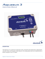
VIESMANN VITOSOL
VITOSOL 100-F
Flat-plate collector, type SV and SH
For installation on flat and pitched roofs and for freestanding
installation
Type SH also for installation on walls
VITOSOL 200-F
Flat-plate collector, type SVE and SHE
For installation on flat and pitched roofs and for freestanding
installation
VITOSOL 200-F
Large area flat-plate collector, type 5DIA
For roof integration on pitched roofs with roof tiles
VITOSOL 200-F, 300-F
Flat-plate collector, type SV and SH
For installation on flat and pitched roofs as well as for roof
integration and freestanding installation
Type SH also for installation on walls
VITOSOL 200-T
Type SP2A
For installation on flat or pitched roofs, on walls and for free-
standing installation
VITOSOL 200-T
Type SPE
For installation on flat and pitched roofs, and for freestanding
installation.
VITOSOL 300-T
Type SP3B
For installation on flat and pitched roofs, and for freestanding
installation.
5822 440 GB 4/2014
Technical guide

Index
1. Principles 1. 1 Viessmann collector range ....................................................................................... 6
1. 2 Parameters for collectors .......................................................................................... 7
■Area designations ................................................................................................. 7
■Collector efficiency ................................................................................................ 7
■Thermal capacity ................................................................................................... 9
■ Idle temperature .................................................................................................... 9
■Steam production capacity .................................................................................... 9
■ Solar coverage ...................................................................................................... 10
1. 3 Orientation, inclination and shading of the receiver surface ..................................... 10
■ Inclination of the receiver surface ......................................................................... 10
■ Orientation of the receiver surface ........................................................................ 10
■ Avoiding shading of the receiver surface .............................................................. 10
2. Vitosol 100-F, type SV1 and SH1 2. 1 Product description ................................................................................................... 12
■ Benefits ................................................................................................................. 12
■ Delivered condition ............................................................................................... 12
2. 2 Specification ............................................................................................................. 12
2. 3 Approved quality ....................................................................................................... 14
3. Vitosol 200-F, type SVE and SHE 3. 1 Product description ................................................................................................... 15
■ Benefits ................................................................................................................. 15
■ Delivered condition ............................................................................................... 15
3. 2 Specification ............................................................................................................. 16
3. 3 Approved quality ....................................................................................................... 17
4. Vitosol 200-F, type SV2 and SH2 4. 1 Product description ................................................................................................... 18
■ Benefits ................................................................................................................. 18
■ Delivered condition ............................................................................................... 19
4. 2 Specification ............................................................................................................. 20
4. 3 Approved quality ....................................................................................................... 21
5. Vitosol 200-F, type 5DIA 5. 1 Product description ................................................................................................... 22
■ Benefits ................................................................................................................. 22
■ Delivered condition ............................................................................................... 22
5. 2 Specification ............................................................................................................. 23
5. 3 Approved quality ....................................................................................................... 24
6. Vitosol 300-F, type SV3 and SH3 6. 1 Product description ................................................................................................... 25
■ Benefits ................................................................................................................. 25
■ Delivered condition ............................................................................................... 26
6. 2 Specification ............................................................................................................. 27
6. 3 Approved quality ....................................................................................................... 28
7. Vitosol 200-T, type SP2A 7. 1 Product description ................................................................................................... 29
■ Benefits ................................................................................................................. 29
■ Delivered condition ............................................................................................... 30
7. 2 Specification ............................................................................................................. 30
7. 3 Approved quality ....................................................................................................... 31
8. Vitosol 200-T, type SPE 8. 1 Product description ................................................................................................... 32
■ Benefits ................................................................................................................. 32
■ Delivered condition ............................................................................................... 32
8. 2 Specification ............................................................................................................. 33
8. 3 Approved quality ....................................................................................................... 33
9. Vitosol 300-T, type SP3B 9. 1 Product description ................................................................................................... 34
■ Benefits ................................................................................................................. 34
■ Delivered condition ............................................................................................... 34
9. 2 Specification ............................................................................................................. 35
9. 3 Approved quality ....................................................................................................... 36
10. Solar control units 10. 1 Solar control module, type SM1, part no. 7429 073 ................................................. 38
■ Specification .......................................................................................................... 38
■ Delivered condition ............................................................................................... 38
■ Tested quality ........................................................................................................ 38
10. 2 Vitosolic 100, type SD1, part no. Z007 387 .............................................................. 39
■ Specification .......................................................................................................... 39
■ Delivered condition ............................................................................................... 39
■ Tested quality ........................................................................................................ 39
Index
2VIESMANN VITOSOL
5822 440 GB

10. 3 Vitosolic 200, type SD4, part no. Z007 388 .............................................................. 40
■ Specification .......................................................................................................... 40
■ Delivered condition ............................................................................................... 41
■ Tested quality ........................................................................................................ 41
10. 4 Functions .................................................................................................................. 42
■ Allocation to solar control units ............................................................................. 42
■ Cylinder temperature limit ..................................................................................... 42
■ Collector cooling function with Vitosolic 100 and 200 ........................................... 42
■ Reverse cooling function with Vitosolic 100 and 200 ............................................ 42
■ Collector emergency stop ..................................................................................... 42
■ Minimum collector temperature limit ..................................................................... 42
■ Interval function ..................................................................................................... 43
■ Cooling function in Vitosolic 200 (only in systems with one consumer) ................ 43
■ Frost protection ..................................................................................................... 43
■ Thermostat function with solar control module and Vitosolic 100 ......................... 43
■ Vitosolic 200 thermostat function, ΔT control and time switches .......................... 43
■ Speed control with solar control module ............................................................... 43
■ Vitosolic 100 speed control ................................................................................... 43
■ Vitosolic 200 speed control ................................................................................... 44
■ Heat statement with solar control module and Vitosolic 100 ................................ 44
■ Vitosolic 200 heat statement ................................................................................. 44
■ Suppression of DHW cylinder reheating by the boiler with solar control module .. 44
■ Suppression of DHW cylinder reheating by boiler with the Vitosolic 100 .............. 44
■ Suppression of DHW cylinder reheating by boiler with the Vitosolic 200 .............. 45
■ Suppression of reheating by the boiler with central heating backup, with solar
control module ...................................................................................................... 46
■ Auxiliary function for DHW heating with solar control module .............................. 46
■ Auxiliary function for DHW heating with Vitosolic 100 .......................................... 46
■ Auxiliary function for DHW heating with Vitosolic 200 .......................................... 46
■ External heat exchanger with solar control module .............................................. 47
■ External heat exchanger with Vitosolic 100 .......................................................... 48
■ External heat exchanger with Vitosolic 200 .......................................................... 48
■ External heat exchanger in large solar thermal systems ...................................... 49
■ Bypass circuits to Vitosolic 200 ............................................................................. 49
■ Parallel relay with Vitosolic 200 ............................................................................ 50
■ Cylinder 2 (to 4) on with Vitosolic 200 ................................................................... 50
■ Cylinder heating with Vitosolic 200 ....................................................................... 50
■ Cylinder priority control with Vitosolic 200 ............................................................ 50
■ Utilisation of excess heat with Vitosolic 200 ......................................................... 50
■ Cyclical heating ..................................................................................................... 50
■ Relay kick with solar control module ..................................................................... 51
■ Relay kick with Vitosolic 200 ................................................................................. 51
■ SD module with Vitosolic 200 ............................................................................... 51
10. 5 Accessories .............................................................................................................. 52
■ Allocation to solar control units ............................................................................. 52
■ Contactor relay ...................................................................................................... 52
■ Immersion temperature sensor ............................................................................. 52
■ Immersion temperature sensor ............................................................................. 53
■ Collector temperature sensor ................................................................................ 53
■ Stainless steel sensor well .................................................................................... 53
■ Heat meter ............................................................................................................ 53
■ Solar cell ............................................................................................................... 54
■ Large display ......................................................................................................... 54
■ High limit safety cut-out ......................................................................................... 54
■ Temperature controller as temperature limiter (maximum limit) ........................... 55
■ Temperature controller .......................................................................................... 55
■ Temperature controller .......................................................................................... 56
11. DHW cylinders 11. 1 Vitocell 100-U, type CVUA ........................................................................................ 57
11. 2 Vitocell 100-B, type CVB .......................................................................................... 61
11. 3 Vitocell 100-V, type CVS .......................................................................................... 66
11. 4 Vitocell 100-V, type CVW ......................................................................................... 71
■ Solar internal indirect coil set ................................................................................ 73
11. 5 Vitocell 300-B, type EVB ........................................................................................... 75
11. 6 Vitocell 140-E, type SEI and Vitocell 160-E, type SES ............................................. 79
11. 7 Vitocell 340-M, type SVK and Vitocell 360-M, type SVS .......................................... 82
11. 8 Vitocell 100-V, type CVA .......................................................................................... 88
11. 9 Vitocell 300-V, type EVI ............................................................................................ 94
Index (cont.)
VITOSOL VIESMANN 3
5822 440 GB

12. Installation accessories 12. 1 Solar-Divicon and solar pump assembly .................................................................. 99
■ Versions ................................................................................................................ 99
■ Design ................................................................................................................... 99
■ Clearances ............................................................................................................ 100
■ Specification .......................................................................................................... 100
12. 2 Connecting tee .......................................................................................................... 102
12. 3 Connecting line ......................................................................................................... 102
12. 4 Installation kit for connection line .............................................................................. 102
12. 5 Manual air vent valve ................................................................................................ 103
12. 6 Air separator ............................................................................................................. 103
12. 7 Quick-acting air vent valve (with tee) ........................................................................ 104
12. 8 Connecting line ......................................................................................................... 104
12. 9 Solar flow and return line .......................................................................................... 104
12.10 Connection accessories for residual lengths of solar flow and return lines .............. 104
■ Connecting kit ....................................................................................................... 104
■ Connection set ...................................................................................................... 104
■ Connection set with locking ring fitting .................................................................. 105
12.11 Fill valve .................................................................................................................... 105
12.12 Manual solar fill pump ............................................................................................... 105
12.13 Solar expansion vessel ............................................................................................. 105
■ Layout and function ............................................................................................... 105
■ Specification .......................................................................................................... 106
12.14 Stagnation cooler ...................................................................................................... 106
12.15 Automatic thermostatic mixing valve ........................................................................ 107
12.16 Thermostatic DHW circulation set ............................................................................ 107
12.17 Three-way diverter valve .......................................................................................... 107
12.18 Threaded DHW circulation fitting .............................................................................. 107
13. Design information regarding
installation
13. 1 Snow load and wind load zones ............................................................................... 108
13. 2 Distance from the edge of the roof ........................................................................... 108
13. 3 Routing pipework ...................................................................................................... 108
13. 4 Equipotential bonding/lightning protection of the solar thermal system .................... 108
13. 5 Thermal insulation .................................................................................................... 109
13. 6 Solar lines ................................................................................................................. 109
13. 7 Collector fixing .......................................................................................................... 110
■ Above roof installation ........................................................................................... 110
■ Roof integration ..................................................................................................... 111
■ Flat roof installation ............................................................................................... 111
■ Installation on façades .......................................................................................... 111
14. Design information regarding
installation on pitched roofs —
above roof installation
14. 1 Above roof installation with rafter anchors ................................................................ 112
■ General information .............................................................................................. 112
■ Vitosol-F flat-plate collectors ................................................................................. 114
■ Vitosol 200-T vacuum tube collectors, type SP2A and Vitosol 300-T, type SP3B 115
■ Vitosol 200-T vacuum tube collectors, type SPE .................................................. 116
■ Support on pitched roofs ....................................................................................... 117
14. 2 Above roof installation with rafter hooks ................................................................... 117
■ General information .............................................................................................. 117
■ Vitosol-F flat-plate collectors ................................................................................. 117
■ Vitosol 200-T vacuum tube collectors, type SP2A and Vitosol 300-T, type SP3B 118
■ Vitosol 200-T vacuum tube collectors, type SPE .................................................. 119
14. 3 Above roof installation with rafter flanges ................................................................. 120
■ General information .............................................................................................. 120
■ Vitosol-F flat-plate collectors ................................................................................. 121
■ Vitosol 200-T vacuum tube collectors, type SP2A and Vitosol 300-T, type SP3B 121
■ Vitosol 200-T vacuum tube collectors, type SPE .................................................. 122
14. 4 Above roof installation for corrugated sheet roofs .................................................... 123
14. 5 Above roof installation for sheet metal roofs ............................................................. 123
■ General information .............................................................................................. 123
15. Design information regarding
installation on pitched roofs —
roof integration
15. 1 Roof integration with flashing frame ......................................................................... 124
15. 2 Roof integration with flashing frame and side flashing ............................................. 124
■ Installation versions .............................................................................................. 124
■ Required roof area ................................................................................................ 126
■ Routing solar lines through the roof ...................................................................... 126
■ Installation of snow guards ................................................................................... 127
16. Design information on flat roof
installation
16. 1 Determining the collector row clearance z ................................................................ 128
Index (cont.)
4VIESMANN VITOSOL
5822 440 GB

16. 2 Vitosol-F flat-plate collectors (on supports) .............................................................. 128
■ Collector supports with variable angle of inclination ............................................. 129
■ Collector supports with fixed angle of inclination .................................................. 131
16. 3 Vitosol 200-T and Vitosol 300-T vacuum tube collectors (on supports) ................... 132
■ Collector supports with variable angle of inclination ............................................. 133
■ Collector supports with fixed angle of inclination .................................................. 134
16. 4 Vitosol 200-T vacuum tube collectors, type SP2A and type SPE (horizontal) .......... 134
17. Design information for wall instal-
lation
17. 1 Vitosol-F flat-plate collectors, type SH ...................................................................... 135
■ Collector supports – angle γ 10 to 45° .................................................................. 135
17. 2 Vitosol 200-T vacuum tube collectors, type SP2A .................................................... 136
18. Information regarding design and
operation
18. 1 Sizing the solar thermal system ................................................................................ 136
■ System for heating DHW ...................................................................................... 137
■ System for DHW heating and central heating backup .......................................... 138
■ Swimming pool heating system – heat exchanger and collector .......................... 139
18. 2 Solar thermal system operating modes .................................................................... 140
■ Flow rate in the collector array .............................................................................. 140
■ Which operating mode is the right one? ............................................................... 140
18. 3 Installation examples Vitosol-F, type SV and SH ..................................................... 140
■ High-flow operation — single-sided connection .................................................... 140
■ High-flow operation — connection on alternate sides ........................................... 141
■ Low-flow operation — single-sided connection ..................................................... 141
■ Low-flow operation — connection on alternate sides ........................................... 141
18. 4 Installation examples Vitosol 200-T, type SPE ......................................................... 141
■ Vertical installation on pitched roofs, installation on supports or horizontal instal-
lation ..................................................................................................................... 141
■ Horizontal installation on a pitched roof ................................................................ 142
18. 5 Installation examples Vitosol 200-T, type SP2A ....................................................... 142
■ Vertical installation on pitched roofs, installation on supports or horizontal instal-
lation ..................................................................................................................... 143
■ Horizontal installation on pitched roofs and on walls ............................................ 143
18. 6 Installation examples Vitosol 300-T, type SP3B ....................................................... 144
■ Vertical installation on pitched roofs and installation on supports ......................... 144
18. 7 Pressure drop of the solar thermal system ............................................................... 145
■ Pressure drop of the solar flow and return lines ................................................... 145
■ Pressure drop of Vitosol 200-F, type SV and SH .................................................. 146
■ Pressure drop of Vitosol 100-F, type SV and SH .................................................. 146
■ Pressure drop of Vitosol 300-F, type SV and SH .................................................. 147
■ Pressure drop of Vitosol 200-T and Vitosol 300-T ................................................ 148
18. 8 Flow velocity and pressure drop ............................................................................... 148
■ Flow velocity ......................................................................................................... 148
■ Pressure drop of the pipework .............................................................................. 149
18. 9 Sizing the circulation pump ....................................................................................... 150
18.10 Ventilation ................................................................................................................. 151
18.11 Safety equipment ...................................................................................................... 151
■ Stagnation in solar thermal systems ..................................................................... 151
■ Expansion vessel .................................................................................................. 153
■ Safety valve .......................................................................................................... 155
■ High limit safety cut-out ......................................................................................... 155
18.12 Additional function for DHW heating ......................................................................... 155
18.13 Connecting the DHW circulation and thermostatic mixing valve .............................. 156
18.14 Intended use ............................................................................................................. 156
19. Appendix 19. 1 Subsidy programs, permits and insurance ............................................................... 157
19. 2 Glossary .................................................................................................................... 157
20. Keyword index .............................................................................................................................................. 158
Index (cont.)
VITOSOL VIESMANN 5
5822 440 GB

Together with Viessmann heating systems, solar thermal systems cre-
ate an optimum system solution for DHW and swimming pool heating,
central heating backup and other applications.
This technical guide includes a summary of all technical documents
for the required components, as well as design and sizing information
especially for systems for detached houses. This technical guide is a
product-related addition to Viessmann's "Solar thermal systems" tech-
nical guide. You can obtain a printed version from your Viessmann
sales consultant or download it from the Viessmann website
(www.viessmann.de), where you will also find electronic aids regard-
ing collector fixing and maintaining the correct pressure in solar ther-
mal systems.
1.1 Viessmann collector range
Flat-plate and vacuum tube collectors from Viessmann are suitable for
DHW and swimming pool heating, for central heating backup, as well
as for the generation of process heat. The conversion of light into heat
at the absorber is identical for both types of collector.
Flat-plate collectors are easily and safely installed above and integra-
ted into domestic roofs. Increasingly, collectors are also mounted on
walls or as floorstanding units. Flat-plate collectors are more affordable
than vacuum tube collectors. They are used for DHW heating systems,
swimming pool heating and for central heating backup.
In vacuum tube collectors, the absorber is similar to a Thermos flask
in that it is set into an evacuated glass tube. A vacuum has good ther-
mal insulation properties. Heat losses are therefore lower than with
flat-plate collectors, especially with high inside or low outside temper-
atures, i.e. under the particular operating conditions that are to be
expected when heating or air conditioning a building.
In Viessmann vacuum tube collectors, every vacuum tube can be rota-
ted. This means the absorber can be optimally aligned to the sun even
in unfavourable installation situations. Vitosol 200-T vacuum tube col-
lectors, type SP2A and type SPE, which use the heat pipe principle,
can also be mounted horizontally on flat roofs. The yield per m2 col-
lector area is a little reduced in this case, but this can be offset by a
correspondingly larger collector area. The Viessmann "ESOP" calcu-
lation program produces a yield comparison.
Flat-plate collectors cannot be mounted horizontally, as the glass
cover cannot be kept clean simply through rain, and the venting of the
collector would be more difficult. Vitosol-F, type SH and Vitosol 200-T,
type SP2A can also be installed on walls. When installed parallel to a
wall (facing south), on an annual average, approximately 30 % less
radiation hits the collector than in installations on 45° supports. If the
main period of use falls in spring, autumn or winter (central heating
backup), higher yields may still be achieved from the collectors, subject
to the prevailing conditions. It should be noted that installation on walls
is subject to certain legal requirements. For the rules regarding the
implementation of collector systems, see the "technical rules for the
use of linear supported glazing" (TRLV) issued by the Deutsches Insti-
tut für Bautechnik (DIBT) (see chapter "Technical Building Regula-
tions").
Principles
6VIESMANN VITOSOL
1
5822 440 GB

1.2 Parameters for collectors
Area designations
Flat-plate collector Vacuum tube collector
C
A
B
A
C
B
–Gross area A
Describes the external dimensions (length x width) of a collector. It is decisive when planning the installation and when calculating the roof
area required, as well as for most subsidy programs when applying for subsidies.
–Absorber area B
Selectively coated metal area, which is set into the collector.
–Aperture area C
The aperture area is the technically relevant specification for designing a solar thermal system and for the use of sizing programs.
Flat-plate collector:
Area of collector cover through which solar rays can enter.
Vacuum tube collector:
Sum of longitudinal sections of the single tubes. Since the tubes are smaller at the top and bottom with no absorber area, the aperture area
of these devices is slightly larger than the absorber area.
Collector efficiency
The efficiency of a collector (see chapter "Specification" for the rele-
vant collector) specifies the proportion of insolation hitting the absorber
area that can be converted into useable heat. The efficiency depends,
among other things, on the operating conditions of the collector. The
calculation method is the same for all collector types.
Some of the insolation striking the collectors is "lost" through reflection
and absorption at the glass pane and through absorber reflection. The
ratio between the insolation striking the collector and the radiation that
is converted into heat on the absorber is used to calculate the optical
efficiency η0.
When the collector heats up, it transfers some of that heat to the ambi-
ence through thermal conduction of the collector material, thermal
radiation and convection. These losses are calculated by means of the
heat loss factors k1 and k2 and the temperature differential ΔT (given
in K) between the absorber and the surroundings:
ŋ = ŋ0
k1 . ΔT -k2 . ΔT²
EgEg
-
Efficiency curves
The optical efficiency η0 and the heat loss factors k1 and k2 together
with temperature differential ΔT and the irradiance Eg are sufficient to
determine the efficiency curve. Maximum efficiency is achieved when
the differential between the absorber and ambient temperature ΔT and
the thermal losses is zero. The higher the collector temperature, the
higher the heat losses and the lower the efficiency.
The typical operating ranges of the collectors can be read off the effi-
ciency curves. This gives the adjustment options of the collectors.
Typical operating ranges (see following diagram):
1Solar thermal system for DHW at low coverage
2Solar thermal system for DHW at higher coverage
3Solar thermal systems for DHW and solar central heating backup
4Solar thermal systems for process heat/solar-powered air condi-
tioning
The following diagrams show the efficiency curves with respect to the
absorber surfaces of the collectors.
Principles (cont.)
VITOSOL VIESMANN 7
5822 440 GB
1

Flat-plate collectors
Vitosol 100-F, type SV1/SH1
0.30
0.20
Efficiency
0 20 40 60 80 100
Temperature differential
(absorber – environment) in K
0.40
0.50
0.60
0.70
0.80 12
3
4
Vitosol 200-F, type SVE/SHE
0.30
0.20
Efficiency
0 20 40 60 80 100
Temperature differential
(absorber – environment) in K
0.40
0.50
0.60
0.70
0.80 12
3
4
Vitosol 200-F, type SV2/SH2
0.30
0.20
Efficiency
0 20 40 60 80 100
Temperature differential
(absorber – environment) in K
0.40
0.50
0.60
0.70
0.80 12
3
4
Vitosol 200-F, type SV2D
0.30
0.20
Efficiency
0 20 40 60 80 100
Temperature differential
(absorber – environment) in K
0.40
0.50
0.60
0.70
0.80 12
3
4
Vitosol 200-F, type 5DIA
0.30
0.20
Efficiency
0 20 40 60 80 100
Temperature differential
(absorber – environment) in K
0.40
0.50
0.60
0.70
0.80 12
3
4
Vitosol 300-F, type SV3/SH3
0.30
0.20
Efficiency
0 20 40 60 80 100
Temperature differential
(absorber – environment) in K
0.40
0.50
0.60
0.70
0.80 2
3
4
1
0.90
Principles (cont.)
8VIESMANN VITOSOL
1
5822 440 GB

Vacuum tube collectors
Vitosol 200-T, type SP2A
0.30
0.20
Efficiency
0 20 40 60 80 100
Temperature differential
(absorber – environment) in K
0.40
0.50
0.60
0.70
0.80 2
3
4
1
Vitosol 200-T, type SPE
0.30
0.20
Efficiency
0 20 40 60 80 100
Temperature differential
(absorber – environment) in K
0.40
0.50
0.60
0.70
0.80 2
3
4
1
Vitosol 300-T, type SP3B
0.30
0.20
Efficiency
0 20 40 60 80 100
Temperature differential
(absorber – environment) in K
0.40
0.50
0.60
0.70
0.80 2
3
4
1
Thermal capacity
The thermal capacity in kJ/(m2 · K) indicates the amount of heat absor-
bed by the collector per m2 and K. This heat is only available to the
system to a limited extent.
Idle temperature
The stagnation temperature is the maximum temperature that the col-
lector can reach during insolation of 1000 W/m2.
If no heat is drawn from the collector, it will heat up until it reaches the
stagnation temperature. In this state, the thermal losses are of the
same magnitude as the radiation absorbed.
Steam production capacity
The steam production capacity in W/m2 indicates the maximum output
at which a collector produces steam during stagnation and transfers it
to the system, when evaporation occurs.
Principles (cont.)
VITOSOL VIESMANN 9
5822 440 GB
1

Solar coverage
300 350 400 450 500 550
Solar coverage
in %
10
20
30
40
50
60
70
600
80
90
100
Energy (yield) in kWh/(m²/p.a.)
A
B
AConventional sizing for DHW systems in detached houses
BConventional sizing for large solar thermal systems
The solar coverage rate indicates what percentage of the energy
required annually for DHW applications can be covered by the solar
thermal system.
Designing a solar thermal system always entails finding a good com-
promise between yield and solar coverage. The higher the selected
solar coverage, the more conventional energy is saved.
However, this is linked to an excess of heat in summer. This means a
lower average collector efficiency and consequently lower yields
(energy in kWh) per m2 absorber area.
1.3 Orientation, inclination and shading of the receiver surface
Inclination of the receiver surface
The yield of a solar thermal system varies depending on the inclination
and orientation of the collector area. If the receiver surface is angled,
the angle of incidence changes, as does the irradiance, and conse-
quently the amount of energy. This is greatest when the radiation hits
the receiver surface at right angles. In our latitudes, this case never
arises relative to the horizontal. Consequently, the inclination of the
receiver surface can optimise the yield. In Germany, a receiver surface
angled 35° receives approx. 12 % more energy when oriented towards
the south (compared with a horizontal position).
Orientation of the receiver surface
An additional factor for calculating the amount of energy that can be
expected is the orientation of the receiver surface. In the northern
hemisphere, an orientation towards south is ideal. The following figure
shows the interaction of orientation and inclination. Relative to the
horizontal, greater or lesser yields result. A range for optimum yield of
a solar thermal system can be defined between south-east and south-
west and at angles of inclination between 25 and 70°. Greater devia-
tions, for example, for installation on walls, can be compensated for by
a correspondingly larger collector area.
South East
South-east
-20% -40%
-25%
+5%
+10% -15%
±0%
West South
South-west
-40% -20%
-25%
+5%
-15% +10%
±0%
Avoiding shading of the receiver surface
Looking at the installation of a collector facing south, we recommend
that the area between south-east and south-west is kept free of shad-
ing (at an angle towards the horizon of up to 20°). It should be remem-
bered that the system is to operate for longer than 20 years, and that
during this time, for example, trees would grow substantially.
Principles (cont.)
10 VIESMANN VITOSOL
1
5822 440 GB

20°
Principles (cont.)
VITOSOL VIESMANN 11
5822 440 GB
1

2.1 Product description
The selectively coated absorber of the Vitosol 100-F, type SV1A/SH1A
ensures a high level of absorption of the available insolation. The cop-
per pipe shaped like a meander ensures an even heat transfer at the
absorber.
The collector casing features heat-resistant thermal insulation and a
cover made from low ferrous solar glass.
Flexible connection pipes sealed with O-rings provide a secure parallel
connection of up to 12 collectors.
A connection set with locking ring fittings enables the collector array
to be readily connected to the solar circuit pipework. The collector
temperature sensor is mounted in a sensor well set in the solar circuit
flow.
The Vitosol 100-F, type SV1B/SH1B with a special absorber coating
is designed for coastal regions (see chapter "Specification").
ASolar glass cover, 3.2 mm
BCover bracket made from aluminium
CPane seal
DAbsorber
EMeander-shaped copper pipe
FThermal insulation made from mineral fibre
GAluminium frame
HSteel bottom plate with an aluminium-zinc coating
Benefits
■ Powerful, attractively priced flat-plate collector.
■ Absorber designed as meander layout with integral headers. Up to
12 collectors can be linked in parallel.
■ Universal application for above roof and freestanding installation
— either in vertical (type SV) or horizontal (type SH) orientation.
Type SH is suitable for installation on walls.
■ High efficiency through selectively coated absorber and cover made
from low ferrous solar glass.
■ Permanently sealed and highly stable through all-round folded alu-
minium frame and seamless pane seal.
■ Puncture-proof and corrosion-resistant back panel made from zinc-
plated sheet steel.
■ Easy to assemble Viessmann fixing system with statically-tested and
corrosion-resistant components made from stainless steel and alu-
minium – standard for all Viessmann collectors.
■ Quick and reliable collector connection through flexible corrugated
stainless steel pipe push-fit connectors.
Delivered condition
The Vitosol 100-F is delivered fully assembled ready to connect.
2.2 Specification
Vitosol 100-F is available with 2 different absorber coatings. Type
SV1B/SH1B has a special absorber coating that allows these collec-
tors to be used in coastal regions.
Distance to the coast:
■ up to 100 m:
Vitosol 100-F, type SV1 and SH1
12 VIESMANN VITOSOL
2
5822 440 GB

only use type SV1B/SH1B
■ between 100 and 1000 m:
type SV1B/SH1B is recommended
Note
Viessmann accepts no liability if type SV1A/SH1A is used in such
regions.
Type SV1A SH1A SV1B SH1B
Gross area
(required when applying for subsidies)
m22.51
Absorber area m22.32
Aperture area m22.33
Installation position (see following diagram) A (above roof),
C, D
B(above roof),
C, D, E
A (above roof),
C, D
B (above roof),
C, D, E
Clearance between collectors mm 21
Dimensions
Width mm 1056 2380 1056 2380
Height mm 2380 1056 2380 1056
Depth mm 72 72 72 72
The following values apply to the absorber area:
–Optical efficiency % 76 75.4
–Heat loss factor k1W/(m2 · K) 4.14 4.15
–Heat loss factor k2W/(m2 · K2)0.0108 0.0114
Thermal capacity kJ/(m2 · K) 4.7 4.5
Weight kg 41.5 43.9
Liquid content
(heat transfer medium)
litre 1.48 2.33 1.67 2.33
Permiss. operating pressure
(see chapter "Solar expansion vessel")
bar/MPa 6/0.6
Max. stagnation temperature °C 200 196
Steam output
– Favourable installation position W/m260
– Unfavourable installation position W/m2100
Connection Ø mm 22
E
C
B
A
D
90
38
72
2200
2380
1056
KV
KR
Type SV1A/SV1B
KR Collector return (inlet)
KV Collector flow (outlet)
Vitosol 100-F, type SV1 and SH1 (cont.)
VITOSOL VIESMANN 13
5822 440 GB
2

90
38
72
2380
876
1056
KV
KR
Type SH1A/SH1B
KR Collector return (inlet)
KV Collector flow (outlet)
2.3 Approved quality
The collectors meet the requirements of the "Blue Angel" certificate of
environmental excellence to RAL UZ 73.
Tested in accordance with Solar KEYMARK and EN 12975.
CE designation according to current EC Directives.
Vitosol 100-F, type SV1 and SH1 (cont.)
14 VIESMANN VITOSOL
2
5822 440 GB

3.1 Product description
The selectively coated absorber of the Vitosol 200-F, type SVE/SHE
ensures a high level of absorption of the available insolation. The cop-
per pipe shaped like a meander ensures an even heat transfer at the
absorber.
The collector casing features heat-resistant thermal insulation and a
cover made from low ferrous solar glass with anti-reflective coating on
the inside.
Flexible connection pipes sealed with O-rings provide a secure parallel
connection of up to 15 collectors.
A connection set with locking ring fittings enables the collector array
to be readily connected to the solar circuit pipework. The collector
temperature sensor is mounted in a sensor well set in the solar circuit
flow.
D
E
B
A
F
G
H
C
ASolar glass cover with anti-reflective coating on the inside,
3.2 mm
BCover bracket made from aluminium
CPane seal
DAbsorber
EMeander-shaped copper pipe
FThermal insulation made from mineral fibre
GAluminium frame
HSteel bottom plate with an aluminium-zinc coating
Benefits
■ Powerful, attractively priced flat-plate collector
■ Absorber designed as meander layout with integral headers. Up to
15 collectors can be linked in parallel.
■ Universal application for above roof and freestanding installation
— either in vertical (type SV) or horizontal (type SH) orientation.
Type SH is suitable for installation on walls.
■ High efficiency through selectively coated absorber and cover made
from low ferrous solar glass with anti-reflective coating on the inside
of the glass
■ Long-lasting impermeability and high stability thanks to all-round fol-
ded aluminium frame and seamless pane seal
■ Puncture-proof and corrosion-resistant back panel made from zinc-
plated sheet steel
■ Easy to assemble Viessmann fixing system with statically-tested and
corrosion-resistant components made from stainless steel and alu-
minium – standard for all Viessmann collectors
■ Quick and reliable collector connection with flexible corrugated stain-
less steel pipe push-fit connectors
Delivered condition
The Vitosol 200-F is delivered fully assembled ready to connect.
Vitosol 200-F, type SVE and SHE
VITOSOL VIESMANN 15
5822 440 GB
3

3.2 Specification
Note
Viessmann accepts no liability for collectors installed in coastal
regions. Maintain a minimum distance from the coast of 1000 m.
Type SVE SHE
Gross area
(required when applying for subsidies)
m22.51
Absorber area m22.32
Aperture area m22.33
Installation position (see following diagram) A (above roof), C, D B (above roof), C, D, E
Dimensions
Width mm 1056 2380
Height mm 2380 1056
Depth mm 72 72
The following values apply to the absorber area:
–Optical efficiency % 82.7
–Heat loss factor k1W/(m2 · K) 3.721
–Heat loss factor k2W/(m2 · K2)0.019
Thermal capacity kJ/(m2 · K) 6.0
Weight kg 41
Liquid content
(heat transfer medium)
litres 2.68 1.83
Permiss. operating pressure bar/MPa 6/0.6
Max. stagnation temperature °C 209
Steam output
– Favourable installation position W/m260
– Unfavourable installation position W/m2100
Connection Ø mm 22
E
C
B
A
D
90
38
72
2200
2380
1056
KV
KR
Type SVE
KR Collector return (inlet)
KV Collector flow (outlet)
Vitosol 200-F, type SVE and SHE (cont.)
16 VIESMANN VITOSOL
3
5822 440 GB

2380
1056
876
90
KV
KR
39
72
Type SHE
KR Collector return (inlet)
KV Collector flow (outlet)
3.3 Approved quality
The collectors meet the requirements of the "Blue Angel" certificate of
environmental excellence to RAL UZ 73.
Tested in accordance with Solar KEYMARK and EN 12975.
CE designation according to current EC Directives.
Vitosol 200-F, type SVE and SHE (cont.)
VITOSOL VIESMANN 17
5822 440 GB
3

4.1 Product description
The main component of the Vitosol 200-F, type SV2C/SH2C is the
highly selectively coated absorber. It ensures a high absorption of
insolation and low emission of thermal radiation. A meander-shaped
copper pipe through which the heat transfer medium flows is part of
the absorber.
The heat transfer medium absorbs the absorber heat through the cop-
per pipe. The absorber is encased in a highly insulated collector hous-
ing that minimises the heat losses of the collector.
The high-grade thermal insulation provides temperature stability and
is non-outgassing. The collector is covered with a solar glass panel.
The glass has a very low iron content, thereby reducing reflection los-
ses.
Up to 12 collectors can be combined together to create a single col-
lector array. For this purpose, the standard delivery includes flexible
connection pipes with O-rings.
A connection set with locking ring fittings enables the collector array
to be readily connected to the solar circuit pipework. The collector
temperature sensor is mounted in a sensor well set in the solar circuit
flow.
The Vitosol 200-F, type SV2D with a special absorber coating is
designed for coastal regions (see chapter "Specification").
C
E
A
F
H
K
G
D
B
ASolar glass cover, 3.2 mm
BAluminium cover strip in dark blue
CPane seal
DAbsorber
EMeander-shaped copper pipe
FMelamine epoxy foam insulation
GMelamine epoxy foam insulation
HAluminium frame in dark blue
KSteel bottom plate with an aluminium-zinc coating
Benefits
■ Powerful flat-plate collector with a highly selectively coated
absorber.
■ Absorber designed as meander layout with integral headers. Up to
12 collectors can be linked in parallel.
■ Universal application for above roof and freestanding installation
— either in vertical (type SV) or horizontal (type SH) orientation.
Type SH is suitable for installation on walls.
■ Attractive collector design; frame in dark blue. Upon request, the
frame is also available in any RAL colour.
■ The selectively coated absorber, the highly effective thermal insula-
tion and the cover made from low ferrous solar glass ensure a high
solar yield.
■ Long-lasting impermeability and high stability thanks to all-round fol-
ded aluminium frame and seamless pane seal.
■ Puncture-proof and corrosion-resistant back panel.
■ Easy to assemble Viessmann fixing system with statically-tested and
corrosion-resistant components made from stainless steel and alu-
minium – standard for all Viessmann collectors.
■ Quick and reliable collector connection through flexible corrugated
stainless steel pipe push-fit connectors.
Vitosol 200-F, type SV2 and SH2
18 VIESMANN VITOSOL
4
5822 440 GB

Delivered condition
The Vitosol 200-F is delivered fully assembled ready to connect. Viessmann offers complete solar heating systems with Vitosol 200-F
(packs) for DHW heating and/or central heating backup (see pack
pricelist).
Vitosol 200-F, type SV2 and SH2 (cont.)
VITOSOL VIESMANN 19
5822 440 GB
4

4.2 Specification
Vitosol 200-F, type SV is available with 2 different absorber coatings.
Type SV2D has a special absorber coating that allows these collectors
to be used in coastal regions.
Distance to the coast:
■ up to 100 m:
only use type SV2D
■ between 100 and 1000 m:
use of type SV2D is recommended
Note
Viessmann accepts no liability if type SV2C/SH2C is used in these
regions.
Type SV2C SH2C SV2D
Gross area
(required when applying for subsidies)
m22.51
Absorber area m22.32
Aperture area m22.33
Installation position (see following diagram) A (above roof and
roof integration), C,
D
B (above roof and
roof integration), C,
D, E
A (above roof and
roof integration), C,
D
Clearance between collectors mm 21
Dimensions
Width mm 1056 2380 1056
Height mm 2380 1056 2380
Depth mm 90 90 90
The following values apply to the absorber area:
–Optical efficiency % 82.4 81.8
–Heat loss factor k1W/(m2 · K) 3.792 3.538
–Heat loss factor k2W/(m2 · K2)0.021 0.023
Thermal capacity kJ/(m2 · K) 5.0 4.6
Weight kg 41
Liquid content
(heat transfer medium)
litres 1.83 2.48 1.83
Permiss. operating pressure
(see chapter "Solar expansion vessel")
bar/MPa 6/0.6
Max. stagnation temperature °C 186 185
Steam output
– Favourable installation position W/m260
– Unfavourable installation position W/m2100
Connection Ø mm 22
E
C
B
A
D
Vitosol 200-F, type SV2 and SH2 (cont.)
20 VIESMANN VITOSOL
4
5822 440 GB
/