Page is loading ...

Model No. BRD101067G ENG101067
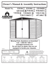
Owner's Manual & Assembly Instructions
AAG01
717381014
* Size rounded o to the nearest foot
BUILDING DIMENSIONS
CAUTION: SOME PARTS HAVE SHARP EDGES. CARE
MUST BE TAKEN WHEN HANDLING THE VARIOUS PIECES
TO AVOID A MISHAP. FOR SAFETY SAKE, PLEASE READ
SAFETY INFORMATION PROVIDED IN THIS MANUAL
BEFORE BEGINNING CONSTRUCTION. WEAR GLOVES
WHEN HANDLING METAL PARTS.
3,0 m x 2,8 m 307,3 cm x 290,8 cm 313,1 cm 297,2 cm 197,8 cm 300,4 cm 283,8 cm 194,6 cm 141,0 cm 165,1 cm
Storage Area: 92 Sq. Ft. 551 Cu. Ft.
8,5 m2 15,6 m3
Exterior Dimensions Interior Dimensions Door
*Approx. Base (Roof Edge to Roof Edge) (Wall to Wall) Opening
Size Size Width Depth Height Width Depth Height Width Height
10' x 10' 121" x 114 1/2" 123 1/4" 117" 77 7/8" 118 1/4" 111 3/4" 76 5/8" 55 1/2" 65"
Missing Parts, Questions on Assembly?
Call: 1-800-851-1085 or
Do not return to dealer, they are not
equipped to handle your requests.
R

114 1/2"
290,8 cm
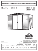
The Base For Your Building
FRONT
(DOOR)
FRONT
(DOOR)
Base
S09
Note: Finished Slab dimensions, with lumber removed.
No matter which of the options below you choose for a base, an ARROW ANCHORING KIT is
recommended as an e ective method of properly securing your building after assembly is complete.
OPTION 1: Directly on ground (earth)
Assemble your building directly on level ground (grass, dirt, rock, sand, etc.). If you choose this option Arrow has a simple kit available to
provide a oor inside the shed to keep stored items o the ground. This kit can be used to support a plywood oor (wood not included)
or be lled with sand/rock to provide a solid surface. (Order No. FB109-A or 68385-A)
Allow 1 - 2 hours for construction.
OPTION 2: Wood Platform
If you decide to build your own base, be sure to select the appropriate materials.
These are the recommended materials for your base:
2 x 4's (38 mm x 89 mm) Pressure Treated Lumber
5/8" (15,5 mm) 4 x 8 (1220 mm x 2440 mm) Plywood-exterior grade NOTE: Pressure Treated Lumber must not be used where it
will make contact with your storage building. The properties of Pressure Treated Lumber will cause accelerated corrosion.
If Pressure Treated Lumber comes in contact with your storage building your warranty will be voided.
10 & 4 penny Galvanized Nails Concrete Blocks (optional)
The platform should be level and at (free of bumps, ridges etc.)
to provide good support for the building. The necessary materials
may be obtained from your local lumber yard.
To construct the base follow instructions and diagram.
Construct frame (using 10 penny galvanized nails)
Measure 16"/24" (40,6 cm/61,0 cm) sections to construct
inside frame (see diagram)
Secure plywood to frame (using 4 penny galvanized nails)
Allow 6 - 7 hours for construction.
OPTION 3: Concrete Slab
The slab should be at least 4" (10,2 cm) thick. It must be level and at to provide good support for the frame.
The following are the recommended materials for your base.
1 x 4's (19 mm x 89 mm) (will be removed once the concrete cures)
Concrete Sheet of 6 mil plastic
We recommend for a proper strength concrete to use a mix of:
1 part cement 3 parts pea sized gravel 2 1/2 parts clean sand
Prepare the Site/Construct a Base
1. Dig a square, 6" (15,2 cm) deep into the ground (remove grass).
2. Fill up to 4" (10,2 cm) in the square with gravel and tamp rm.
3. Cover gravel with a sheet of 6 mil plastic.
4. Construct a wood frame using four planks of 1x4 (19 mm x 89 mm)
lumber.
5. Pour in concrete to ll in the hole and the frame giving a
total of 4" (10,2 cm) thick concrete. Be sure surface is level.
Allow 3 - 5 hours for construction and a week for concrete curing time.
Note: Platform/Slab will extend 9/16" (1,4 cm) beyond oor
frame on all four sides. Seal this 9/16" (1,4 cm) of wood with a
roo ng cement (not included), or bevel this 9/16" (1,4 cm) of
concrete when pouring, for good water drainage.
121"
307,3 cm
16"/24"
40,6 cm/61,0 cm
121"
307,3 cm
9
114 1/2"
290,8 cm

It is important that the entire oor frame be anchored after the building is erected.
Below are recommended ways of anchoring.
Anchoring Down The Building
Anchoring
A10
Arrow Anchoring Kit: (Model No. AK100 or 68383)
Recommended for use with the concrete base.
Contains: Corner gussets, perimeter clips, hardware,
1/4" masonary drill bit and installation instruction.
Anchoring into Concrete:
1. For poured concrete slab or footing or patio blocks:
Use 1/4" x 2" (6 mm x 51 mm) Lag Screws.
2. For Anchor Post of Concrete poured after building is
erected: Use 1/4" x 6" (6 mm x 152 mm) Lag Screws.
Arrow Anchoring Kit: (Model No. AK4 or 60298)
Recommended for use with any suggested base.
Contains: 4 Anchors with Cable, Clamps and
installation instruction.
Anchoring into Wood/Post:
Use 1/4" (6 mm) Wood Screws. There are 1/4" (6 mm)
dia. holes provided in the frames for proper anchoring.
OVER THE BEAMS
AND INTO THE GROUND
1. 2.
1. 2.
10

Remove from bag of screws
and save for the last step
67545
Weather Stripping (1)
5971
Roof Beam Bracket (4)
66382
Lower Door Guide (4)
66183
Roof Trim Cap
(2 right & 2 left)
66045
Handle (2)
66646
Washer (381)
(10 sheets of 40)
65109
#8-32 Acorn Nut (4)
(Packed with Screws)
67468
Peak Cap (2)
65004
#8Ax5/16" (8 mm)
Screw (344)
65923
#8-32x3/8" (10 mm)
Bolt (157)
65900A
#10Bx1/2" (13 mm)
Black Screw (8)
(Packed with Screws)
65103
#8-32 Hex Nut (157)
Hardware
S11
6228
Track Support (2)
66769
Door Slide (4)
11

Parts List
Assembly Part Part Quantity Check
Key No. Number Description in Carton List
1 3719 Door Handle Brace 2
2 5986 Rear Wall Angle 2
3 6000 Right Gable 2
4 6001 Left Gable 2
5 6015 Side Roof Trim 4
6 10497 Horizontal Door Brace 4
7 6300 Vertical Door Brace 2
8 6403 Door Track Splice 1
9 6633 Corner Panel 4
10 6627 Wall Panel 8
11 6529 Roof Panel 4
12 6635 Gable Brace 2
13 6640 Right Roof Panel 2
14 6641 Left Roof Panel 2
15 6869 Ridge Cap 2
16 9917 Rear Wall Channel 2
17 10477 Right and Left Doors 2
18 8934 Ramp 1
19 8936 Rear Floor Frame 2
20 9923 Side Wall Channel 4
21 10518 Roof Beam 8
22 9298 Side Wall Angle 4
23 9299 Side Floor Frame 4
24 9365 Front Wall Channel 2
25 9366 Door Track 2
26 9367 Front Floor Frame 2
27 9370 Door Jamb 2
28 9374 Front Wall Panel 2
29 69835 Edge Trim (Green) 4
QS12et
12

13
Assembly by Key No.
S13et
5
514
15
11
11
13
22
22
21
21
15
11
13
11
2121 3
21 45
4
3
21 21
12
5
21
14
10
10
910
2
12
10
10
10
22
2
9
20
10
10
20
9
19
23
17
17 7
7
6
6
26
23
27
27
18
24
28 22
1
1
28
24
925
20
6
68
25
23
19
20 16
16
23
26
29
29
29
29

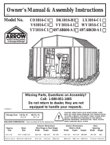
The front oor frame is made up of
three pieces. The side floor frames
and the rear floor frame are made
up of two pieces. The holes in these
pieces will align when the pieces are
positioned with correct amount of
overlap. The illustrations below show
the proper overall length for the sides,
rear and front. Proceed as follows:
1 Place the front floor frames as
shown. Center the ramp, with drain
holes facing outside, on top of the two
front oor frames. Join the frames by
inserting eight screws.
2 Overlap the side floor frames
and the rear oor frames as shown.
The holes in these pieces will align
when the pieces are positioned with
correct amount of overlap. See the
illustrations below for the proper
overall length of the side and rear
oor frames. Join the frames by in-
serting ve bolts into each frame set
as shown.
3 Double check the length of each
and set these pieces aside for later
use.
Step 1
S14 ctr
Parts Needed For
Floor Frame Assemblies
8934 Ramp (1)
9367 Front Floor Frame (2)
8936 Rear Floor Frame (2)
9299 Side Floor Frame (4)
9367
STEP
1
8934
9367
DRAIN HOLES FACE
OUTSIDE
Front Floor
Frame Assembly
119 3/8" 303,2 cm
8936
9299
9367
8934
9367
9299
9299
Side Floor Frame 112 7/8"
286,7 cm
8936 8936
Rear Floor Frame 119 3/8"
303,2 cm
STEP
2
STEP
3
112 7/8" 286,7 cm
119 3/8" 303,2 cm
Front & Rear
119 3/8" 303,2 cm
112 7/8" 286,7 cm
Side
(8) (15)
14

Step 2
S15 ctr
Parts Needed For
Frame Assemblies
The main frame pieces reinforce
the walls. These pieces will later be
installed in the center and at the top
edge of the side walls and the rear
wall. Proceed as follows:
1 Overlap the rear wall channel
pieces as shown in the figure and
fasten the two pieces together with
one bolt in the center hole (three
holes will align).
2 Make two side wall channels by
overlapping the side wall channel
pieces as shown. Fasten each set
together with one bolt in the center
hole of each set.
3 Overlap the rear wall angle
pieces as shown in the figure and
fasten them together with one bolt
in the center hole.
4 Make two side wall angles by
overlapping the side wall angle pieces
as shown. Fasten each set together
with one bolt in the center hole.
5 Double check the length of each
and set these pieces aside for later
use.
5986 Rear Wall Angle (2)
9917 Rear Wall Channel (2)
9923 Side Wall Channel (4)
9298 Side Wall Angle (4)
STEP
1
Rear Wall Channel
118 1/8" 300,0 cm
STEP
2
9917
9923
Side Wall Channels
111 5/8" 283,5 cm
9923
Rear Wall Angle
118 1/8" 300,0 cm
5986
5986
9298
9298 Side Wall Angles
111 5/8" 283,5 cm
STEP
34
Rear Wall Channel
118 1/8" 300,0 cm
Side Wall Channels
111 5/8" 283,5 cm
Side Wall Angles
111 5/8" 283,5 cm
Rear Wall Angle
118 1/8" 300,0 cm
STEP
5
STEP
9917
(6)
15

The roof beams join the two gables
and support the roof panels. The
main roof beam is made up of four
pieces overlapped back to back at
the center. The left and right roof
beam assemblies are made up of
two pieces.
Hint: These pieces are force-fitted,
so you may have to press hard to join
them together.
1 Place the end of one roof beam
inside a second roof beam so that the
six holes in each piece align. Make
four sets of roof beams by repeating
this procedure. Do not insert bolts
yet.
2 Take two of the pressed-together
roof beams and join them as shown
to form the main roof beam assem-
bly. Hold the assembly together and
fasten with 14 bolts. Build only one
Doubled Beam Assembly.
3 Fasten the other two pressed-
together roof beams with eight bolts
to make the left and right roof beam
assemblies.
4 Double check the length of each
and set these pieces aside for later
use.
Step 3
S16 ctr
Parts Needed For
Roof Beam Assemblies
10518 Roof Beam (8)
10518
STEP
1Roof Beam 113 7/16" 288,1 cm
Build one Doubled Main Roof
Beam Assembly for Peak in Roof
END
VIEW
10518
Build two Single Beam Assemblies
STEP
2
STEP
3
10518
10518
10518
10518
ASSEMBLED
113 7/16"
288,1 cm
113 7/16"
288,1 cm
(30)
16

Step 4
A17 ctr
Parts Needed For
Door Track Assembly
6403 Door Track Splice (1)
9366 Door Track (2)
The door track assembly supports the
sliding doors and reinforces the front
wall. It is made up of three pieces.
1 Using the door track splice,
(painted), join the door track
(galvanized) pieces end-to-end as
shown.
2 Insert four screws from the
underside only.
Hint: The holes in the top side of the
door track assembly are for fastening
the gable to the top of the front wall
in a later step.
3 Position door slides onto the
legs, from the end of door track
assembly, as shown in the end view.
4 Set this piece aside for later use.
(4)
17
NOTE:
Door Track Splice (painted part)
STEP
1
STEP
2
Long Leg
on Top
Short Leg
on Bottom
9366
9366
6403
66769
66769
STEP
3
STEP
4
118 1/8"
300,0 cm
118 1/8"
300,0 cm
CORRECT INCORRECT
Long Leg
on top.
Door Slide
END VIEW
6403
Painted Part
9366
9366

Front Floor Assembly (1)
Side Floor Assembly (2)
Rear Floor Assembly (1)
Parts Needed For
Floor Frame
Step 5
S18 ctr
The oor frame must be square
and level or holes will not align.
1 Assemble the four corners of
the oor frame using two screws at
each corner as shown. At the front
corners fasten bolts through from
the bottom with nuts on top.
2 Measure the oor frame diagonally.
When the diagonal measurements
are equal, the oor frame is square.
NOTE
If using a wood platform or
concrete slab do not fasten the
oor frames to your base at this
time. You will anchor the
building after it is erected.
STEP
1
9299
RIGHT
REAR
8936
Level
9299
RIGHT
FRONT
9367
STEP
2
When Diagonal Measurements
are Equal the Floor Frame
is Square.
FRONT
(8) (2)
18

6627 Wall Panel (2)
9374 Front Wall Panel (2)
6633 Corner Panel (4)
Step 6
QS19 ctr
Parts Needed For
Corners
STEP
1
6627
9374 9374
6633
6633
REAR
FRONT
9374
Panels rest on
frame as shown
6633
SIDE TOP VIEW
Narrow
Side
6633
6627
Wide Side
STEP
3
STEP
2
STEP
4
6627
9374
6633
6627
#8-32x3/8" Bolt (10 mm)
Washer
Crimped Rib
Underneath
SIDE
#8Ax5/16" Screw (8 mm)
#8-32 Hex Nut
1 Position a corner panel at the
corner of the oor frame as shown.
The widest part of each corner panel
must be placed along the side of the
building for all four corners. Fasten
the corner panel to the oor frame
with four screws.
Support the corner panel with a step
ladder until a wall panel is attached.
2 Attach the front wall panels to
the front corner panels, as shown.
A small gap will exist between front
wall panel and ramp.
3 Attach the wall panels to the rear
corner panels, as shown.
NOTE
Be careful to install the correct
panel in each position as shown
NOTE
The remainder of the building assembly
requires many hours and more than one
person. Do not continue beyond this
point if you do not have enough time to
complete the assembly today. A partially
assembled building can be severely
damaged by light winds.
4 Double-check the part numbers of
the wall panels, before proceeding.
The oor frame must be square
and level or holes will not align.
Each screw and bolt in the wall
requires a washer.
CORRECT INCORRECT
(38) (4)
19

The main frame pieces give rigidity to
the side walls and provide a surface
for attaching the gables which sup-
port the roof.
1 Fasten the rear wall angle as-
sembly across the inside top of the
rear wall using screws.
2 Fasten the rear wall channel as-
sembly across the middle of the rear
wall using screws.
3 Fasten the side wall angles across
the inside top of the side panels using
screws. Side wall angles must overlap
rear wall angle in corners.
4 Fasten the side wall channel as-
semblies across the middle of the
side panels using screws. Fasten
overlaps in rear corners with screws.
5 Fasten the door track assembly
(holes on top) across the top of the
front wall panels using screws. See
the gure.
NOTE
The wall channels behind the
front wall panels will be installed
in a later step.
Door Track Assembly (1)
Rear Wall Angle Assembly (1)
Side Wall Angle Assemblies (2)
Rear Wall Channel Assembly (1)
Side Wall Channel Assemblies (2)
Parts Needed For
Frames
Step 7
S20 ctr
5
Short Leg
on Bottom
STEP
3
Opening
Facing in
STEP
4
Long Leg
on Top
STEP
FRONT
9366
FRONT
9923
9298
FRONT
Wall Angles
Must Face
Inside
Building 9917
5986
1
STEP
2
STEP
Door Track Assembly
(54) (2)
20

6627 Wall Panel (6)
Parts Needed For
Wall Panels
Step 8
QS21 ctr
Each wall panel has a crimped rib
on one side. The crimped rib should
go under the rib of the panel that
follows it.
1 Locate all of the wall panels and
set each one alongside the building.
2 Be sure that you have the correct
panels in each position. Do this
by overlapping the panels and
determining if the holes line up with
the holes in the frame.
3 Fasten the wall panels at the top
and bottom with screws.
4 Fasten the center of each panel to
the wall channel with screws. Fasten
overlapping ribs using a bolt and nut
with two screws.
5 When you have attached all wall
panels in the correct positions, the
building will look like this.
STEP
2
6627
Panels rest on
frame as shown
6627
6627
6627
6627
6627
Crimped Rib
Underneath
Detail Showing
Center of Panel
Screwed to
Wall Channel
Bolt and nut
does not go thru
wall channel
at overlap
STEP
4
STEP
3
Use bolts and nuts
thru wall angle overlap
at the top of panel at
sides and rear.
STEP
5
STEP
1
(84) (15)
21

9370 Door Jamb (2)
9365 Front Wall Channel (2)
Parts Needed For
Front Channel/Door Jamb
Step 9
U22 ctr
The door jambs reinforce the door
opening and provide an attractive
trim. Follow these steps for both
door jambs.
1 Fasten the front wall channels
in their positions between the end of
the side wall channel and the corner
panel using screws. Do not put a
screw in the hole at the end behind
the door opening at this time.
2 Fasten a door jamb to the front
panel with two bolts, nuts and acorn
nuts, as shown.
3 Fasten the center of the door
jamb to the front wall panel and the
front wall channel with two screws.
4 Fasten the top of the door jamb
to the door track with two screws. Do
the same for the bottom into frame.
Repeat steps 2 through 4 for the
opposite door jamb.
Acorn Nut
Hex Nut
9370
FRONT
Screw
Screw
TOP VIEW
TOP VIEW
Door Track
9370
Front Wall Channel
Front Wall Channel
Cross-Section
Top View
(2) bolts
Bolt
INSIDE OF
BUILDING
9365
FRONT
TOP VIEW
Screw Screw
Door Track
STEP
4
STEP
3
STEP
2
STEP
1
Acorn Nut
(18) (4)
22

Parts Needed For
Gable Assemblies
Step 10
A23et ctr
6000 Right Gable (2)
6001 Left Gable (2)
5971 Roof Beam Bracket (4)
STEP
1
5971
Roof Beam
Brackets
Washer
6001
6000
FRONT
(8)
The gables go on top of the front and
rear walls to support the roof beams.
NOTE
The gables are packed nested
together and might be mistaken
as one piece. Carefully separate
them before continuing.
1 Apply edge trim to the top edge
of the right gables and left gables.
2 Attach the four roof beam
brackets to the gables using two
bolts, washers and nuts.
NOTE
Mounting leg of bracket must
face toward center of gable
and holes closest together
must be on top
To avoid mishap on the sharp
edge the edge trim must remain
in place on the top edge of the
gable until right and left roof
panels are in place.
CAUTION:
Edge Trim
(Plastic Piece)
STEP
2
23

Parts Needed For
Gables/Braces
Step 11
A24 ctr
Left Gable Assemblies (2)
Right Gable Assemblies (2)
6635 Gable Brace (2)
1 Lift and fasten a right and left gable,
under angle at corner, to the door
track and rear wall angle with screws.
Hint: On the rear gable, use a bolt
and nut at the overlapping rear wall
angle. On the front gable, leave out
2 screws closest to center gable leg.
2 Join the left and right gables
together with a gable brace using a
bolt and nut in the bottom hole only.
3 Repeat Steps 1 & 2 for the door
track on the front of building, except
for the track supports, fasten as
shown.
STEP
3
Track Supports 6228
STEP
1Gable
STEP
2
6635 Gable Brace
(20) (5)
24

Step 12
A25 ctr
Parts Needed For
Roof Beams
Main Roof Beam (1)
Single Roof Beam (2)
1 Spread the two halves of the main
roof beam and fasten the roof beam
to the gable brace of the front gable.
2 Fasten the other end of the main
roof beam to the gable brace of the
rear gable.
3 Fasten the single roof beams,
small holes on top, as shown using
bolts and nuts.
STEP
1
Spread Two Halves
Of Roof Beams
STEP
3
Single Roof Beam Assembly
STEP
2
Main Roof Beam Assembly
(12)
25

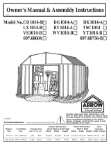
Step 13
S26et ctr
Parts Needed For
Right Roof Panel 6640 Right Roof Panel (1)
Installing the roof panels is best done
with a step ladder. Begin installing
roof panels at the back right corner
of the building. Each screw and bolt
in the roof requires a washer.
NOTE
Measure the building diagonally
again and make adjustments to
make sure the building is square.
This will make the roof panels t
better, and holes will align.
NOTE
If a Roof Beef-Up Kit was
purchased, assemble prior to
attaching the roof panels.
1 Locate all the roof panels by their
numbers and place them on the
ground alongside the building in their
proper positions.
2 Position a right roof panel at the
back right corner and fasten to the
top roof beam using screws.
3 Remove edge trim from the left
gable under the roof panel.
4 Continue fastening the right roof
panel to the gable and lower roof
beam using screws, bolts and nuts as
shown. Do not fasten the lower end
of the panels to the side wall angles
at this time.
6640 Right Roof Panel
FRONT
Washer
Bolt
Gable
STEP
1
Nut
5
6789
1 - 4
6641
8
6
2
4
1
5
7
3
FRONT
6529
6529
6640
6640
6529
6529
6641
10 thru 13
(8) (5)
STEP
2
Hint: Follow the fastener sequence
shown for proper alignment.
STEP
3
STEP
4
26

1 Install a left roof panel at the left
rear corner of the roof.
2 Install 4 roof panels in the se-
quence and positions shown. Follow
fastener sequence and instructions
in Steps 13 thru 15 while fastening
roof panels.
NOTE
Narrow roof panel rib (with bead
on it) is always overlapped by
wide rib of adjacent panel
3 Cover the joint at the peak with
weather stripping tape. Unroll the
tape and press it down over the
opening at the ridge as you install
each roof panel. Do not cut the tape
at this time.
Step 14
S27 ctr
Parts Needed For
Roof Assembly
6641 Left Roof Panel (1)
6529 Roof Panel (4)
NOTE
If roof beam holes do not line up
with the roof panel holes, shift the
building from left to right.
If this does not help, your building
may not be level. Shim the
corners until holes line up.
Fasten At
Overlap with
Bolt
STEP
STEP
Screws To
Roof Beam
2
FRONT
1
STEP
3
6641
8
6
2
4
1
5
7
3
FRONT
6529
6529
6640
6640
6529
6529
6641
6529 Roof Panel
Screws To
Roof Beam
6641 Left Roof Panel
Do not fasten
at this time
(40) (9)
27
/