Page is loading ...

13
Anwenderhinweise
Technische Information
User Manual
Technical Information
Mode d’emploi
Informations techniques
Manual del usuario
Información técnica
Istruzioni per l’uso
Informazioni tecniche
DE
EN
FR
ES
IT

14
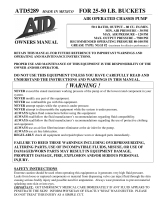
EN
R 1/4“
Ø 52 mm (2.05 in.)
14
mm
(0.55 in.)
43 mm (1.7 in.)
simalube 30
R 1/4“
Ø 52 mm (2.05 in.)
14
mm
(0.55 in.)
62 mm (2.4 in.)
simalube 60
R 1/4“
Ø 52 mm (2.05 in.)
14
mm
(0.55 in.)
100 mm (3.9 in.)
simalube 125
R 1/4“
Ø 52 mm (2.05 in.)
14
mm
(0.55 in.)
193 mm (7.6 in.)
simalube 250
Product Specification
Product automatic long-term grease and oil dispenser
Power generation hydrogen gas producing drycells
Working pressure max. 5 bar
Adjustment stepless 1–12 months (for standard conditions)
Dispensing rate see table on page 15 –17
Operating
temperature
–20°C to +55°C (–4°F to +131°F) ambient temperature
(Note: grease consistency changes with temperature)
Operation/Usage Grease dispenser can be installed in any position, even under
water. Attention: do not expose to direct heat.
Certifications/
Approvals
II 1G Ex ia IIC T6
II 1D Ex iaD 20T 80°C
I M1 Ex ia I
Ingress protection IP68 (dustproof and waterproof)
Usage period within 2 years of production date
Stock temperature recommended at 20°C ± 5°C (65°F ± 5°F)
30 ml 60 ml 125 ml 250 ml
Weight full ~ 82 g ~ 115g ~ 190 g ~ 335 g
Weight empty ~ 55 g ~ 60 g ~ 75 g ~ 111 g

15
Assembly and Installation
1) Open the lubricator outlet by cutting off seal or removing plug.
Do not remove plug from oil filled units! Cut off the
protruding nipple with a knife; a small black point becomes
visible (opening now guaranteed).
2) To start the simalube lubricator, set the gas generator to the
required dispensing time (stepless in months, 1–12) using a
3 mm Allen key. The lubricator is activated once the dispensing
time has been set. Take the required dispensing quantity from
the tables on page 16.
3) Note the starting date on the label using a waterproof pen.
4) Clear grease lines and fill them with the appropriate grease.
Screw simalube onto the greasing point. If necessary, use acces-
sories shown on page 20–22. Apply safety rules.
5) Once the set dispensing time has expired, replace empty lubri-
cator with the same type or refill. Before restarting, clear grease
lines and fill them with the appropriate grease.
6) The gas generator is sufficient to empty the unit once,
irrespective of the dispensing time set.
Security note: If the lubricator is started without opening the outlet or in case of
blocked grease lines within the installation, the pressure in the lubricator can build up
approx. 5 bar. At an overpressure of approx. 6 bar the lubricator breaks at the defined
breaking point between housing and bottom. The pressure behind the piston releases
and oil or grease can come out at the breaking point.
The correct functioning of the lubricator can only be assured if recommended lubricants
(see table on page 19) and original simalube accessories are used, and if the installa-
tion, operating and maintenance instructions are closely followed. The manufacturer
cannot accept any responsibility for damages as a result of ignoring the instructions
mentioned above. Important: Before putting simalube into operation fill extensions and
the lubrication lines with the appropriate simalube greases (cartouches KA0 ...KA25)
using a grease gun. Use only original accessories.
Temperature / Output rate
The output rate can be adjusted as required, depending on the ambient temperature
(see table).
Example: You want to set the dispensing time for a 125 ml simalube for 180 days.
Ambient temperature: 20°C Ambient temperature: 55°C
Setting: 6 Setting: 7

16
EN
simalube 60
Dispensing
time (days) 30 90 180 270 360
ml/day 2.00 0.67 0.33 0.22 0.17
Temperature Setting Setting Setting Setting Setting
–20°C + 2 4 6.5 8
4°C + 2.5 5.5 9 10.5
20°C 136912
40°C 1 3 6.5 9.5 –
55°C 1 3.5 7 10.5 –
+ use larger dispenser with longer dispensing time
– smallest possible output rate reached
simalube 30
Dispensing
time (days) 30 90 180 270 360
ml/day 1.00 0.33 0.17 0.11 0.08
Temperature Setting Setting Setting Setting Setting
–20°C + 2 3.5 5.5 7.5
4°C + 2.5 5 7.5 10.5
20°C 136912
40°C 1 3 6.5 9.5 –
55°C 1 3.5 7 10.5 –
+ use larger dispenser with longer dispensing time
– smallest possible output rate reached
simalube 125
Dispensing
time (days) 30 90 180 270 360
ml/day 4.17 1.39 0.69 0.46 0.35
Temperature Setting Setting Setting Setting Setting
–20°C + 2 4 6.5 8.5
4°C + 2.5 5.5 8 10.5
20°C 136912
40°C 1 3 6.5 9.5 –
55°C 1 3.5 7 10 –
+ use larger dispenser with longer dispensing time
– smallest possible output rate reached
simalube 250
Dispensing
time (days) 30 90 180 270 360
ml/day 8.33 2.78 1.39 0.93 0.69
Temperature Setting Setting Setting Setting Setting
–20°C ++ 2 4.5 7.5 9.5
4°C ++ 2.5 5.5 8 10.5
20°C 136912
40°C 1369–
55°C 1 3.5 6.5 9.5 –
++ use 2-fold adapter
– use smaller dispenser with shorter dispensing time

17
The values relate to laboratory conditions, SL01 with no counterpressure. At low tempe-
ratures in particular, the values may vary between one grease type and another. The
dispensers must be replaced once the dispensing time set has expired, even if they are
not completely empty.
The grease quantity dispensed – counter pressure/resistance from
per day is influenced by: the grease lines
– ambient temperature
– viscosity of the grease
Start-up time:
The lubricator requires a certain start-up time until the lubricant is first dispensed.
The start-up time varies in line with the volume dispensed, dispenser size and operating
temperature selected. At 20°C ambient temperature and a dispensing time setting of
12 months, the dispenser outputs the lubricant within one week. The start-up time dou-
bles at low temperatures (–20°C) or with small dispensers (30 ml).
You can reduce the start-up time in such a case by setting a dispensing time on the
lubricator of one month for one to two days and then changing to the desired dispens-
ing time.
Calculation Pro:
An online calculation program is available at www.simatec.com (simalube/calculation
pro). This tool calculates the right setting for the simalube lubricator if you enter the
precise operating parameters.
Notes:
In order for the unit to function reliably, it is important to have clear, filled grease lines.
It must be ensured that the grease lines are not blocked. Consequently, the grease lines
should always be cleared with a grease gun before starting.
The simalube can be re-adjusted or switched off during operation.
The values on the gas generator relate to laboratory conditions (see page 15). Depend-
ing on the temperature and setting, it may take several hours (or several days in the
case of long-term settings) until the lubricant is first dispensed.
The user must check the operation of the simalube regularly.
Grease lines should be no longer than 0.5 m. Recommended bore diameter: 6 – 8 mm
Resistance in grease lines has to be minimized, narrow passages and right angles
should be avoided.
Use a mounting support in the event of strong vibrations or high accelerations (for
accessories, see page 21).
The simalube may only be used to supply a single grease point. No branches may be
made.
Once the lubricator is installed and activated, it must not be removed and mounted
onto another lubrication point.

18
EN
Filling and Refilling (for small quantities)
1a. 2a.
3a. 4.
5. 6.
1b. 2b.
3b.
1.
2.
Filling with grease
1a. Push piston all the way forward by blowing
gently with compressed air or with the aid
of a plastic rod (7 mm diameter), towards
the bottom or opening.
2a. Screw on refill nipple (article no. 3012)
and connect grease gun, or screw
connector nipple (3013 or 3014) onto
grease gun. Keep the dispenser pressed
to the adapter during the filling process
so that you do not have to screw on the
refill nipple again. Press grease into the
dispenser. Avoid air bubbles when filling
the unit. Continue the filling process until
the piston has been pushed all the way
back. Do not overfill!
Caution: Lever
presses can create pressure of up to
80 bar, which is enough to destroy
the dispenser.
3a.
Use closing nipple (green) if the dispenser
is to be stored.
4. Position gas generator (make sure the O-ring is positioned correctly)
and attach firmly with a 1.5 – 2.0 Nm torque key.
5. Clip in cover disk.
6. Note grease type and filling date on the label.
Filling with oil
1b. Push the piston all the way back
(towards the gas generator).
2b. Pour in oil through the opening
at the bottom.
3b. Position non-return valve
(yellow, article no. 5060).
4–6 Continue as above.
Refilling with grease or oil
1. Remove cover disk.
2. Unscrew gas generator (SW 21) and
recycle with other batteries. Never remove
near an open flame! Then continue as
above for filling with grease or oil.
Note
To ensure that the simalube lubricator operates
reliably, only greases that have been tested
and approved for use with the simalube
should be used. In particular, it is important to
ensure the good stability of the grease against
bleeding of the base oil and a low consistency
class (max. NLGI 2). No guarantee claims will
be accepted when dispensers are filled by the
user or not explicitly approved lubricants are
used. If in doubt, please contact our Technical
Department or your local distributor.

19
Lubricants
The standard lubricant range suitable for simalube includes modern high quality lubri-
cants tested and modified for the special requirements of grease and oil dispensers.
Datasheets are available online for all lubricants (www.simatec.com). Please refer to these
datasheets for the instructions/safety regulations of the grease/oil manufacturers.
No. Application Temperature range
(in the area of lubrication)
SL01 Multipurpose grease –30 / +120°C
SL02 Multipurpose grease with MoS2–25 / +130°C
SL04 High temperature grease –20 / +160°C
SL06 Fluid grease –20 / +120°C
SL09 Biodegradable grease –20 / +80 / 100°C
SL10 Food industry grease (NSF H1) –30 / +140°C
SL14 Chain oil –10 / +90°C
SL15 High temperature chain oil 0 / +250°C
SL18 Food industry oil (NSF H1) –15 / +150°C
SL24 Grease for a wide temperature range –30 / +150°C
SL25 High temperature grease –20 / +180°C
simalube can also be delivered filled with other lubricants or as an empty unit.
Ask for advice.
The operation of simalube with oils of different viscosities is also possible.
Troubleshooting
Fault Possible cause Remedy
– no grease output – seal not cut off/closing nipple
still in place
– not switched on
– grease lines blocked
– gas generator loose
– open/remove
– switch on
– clear lines with grease gun
– tighten with 2 Nm
– insufficient output – dispensing time too long
– ambient temperature too low
– grease lines blocked/too
narrow
– short-term extreme low
temperatures, piston moves
backwards
– high counter pressure
– set to lower number
– correct setting according to
table, page 16
– clean, allow for free flow of
grease
– none
– clear grease lines, check
installation
– excessive output – dispensing time too short – set to higher number
For other malfunctions contact simatec engineering or your local distributor.
The information provided reflects the manufacturer’s current level of development and
understanding. Subject to change. The products are subject to strict manufacturing con-
trols and meet internal works specifications. As a result of the wide range of conditions
and areas of application possible in each case, no guarantee can be provided for effec-
tiveness or success in each individual instance. No responsibility is accepted for damage
or malfunctions caused by incorrect use or improper work on or with the lubricator.

20
EN
Fixation nipple G½"–R¼"
L25 [ mm ]
Nr. 1015
Bent connection 45°
DR 1/4
Nr. 1001
Bent connection 90°
DR 1/4
Nr. 1002
90° connection with thread (only for oil)
70 mm incl. 2 nuts
L70 [ mm ]
Nr. 1005
Connecting nipple
DR 3/8 R 1/2
Nr. 1010 1011
Reducing nipple
DR 1/8 R 1/4 M6 M8 M8x1 M10 M10x1 M12 M12x1.5 UNF 1/4
Nr. 1020 1021 1022 1023 1024 1025 1026 1027 1028 1121
Extension
L10 35 50 [ mm ]
Nr. 1021 1040 1041
Screwed connection with hole
25 mm incl. 1 nut
L25 60 [ mm ]
Nr. 1045 1046
Y-manifold
Contains reduction 1021
DR 1/4
Nr. 1050
Quick connection
For hose ø 8 mm
DR 1/4
Nr. 1060
Quick connection
For hose ø 8 mm
DR 1/8 R 1/4 R 3/8
Nr. 1070 1071 1072
Accessories
Note: Use only original accessories. If you have technically demanding or unusual
applications, please contact our Technical Department or your local distributor.

21
Hose
Maximum length to greasing point: 0.5 m /available by the metre
Lper meter
Nr. 2000/...m
113
Adapter for Perma clamp
Plastic
D50 [ mm ]
Nr. 2012
Distance holder to clamp for round brush (2013)
H15 [ mm ]
Nr. 2014
Non-return valve
DR 1/8 R 1/4
Nr. 2020 2021
Round brush
Plastic bristles
DxL ø 25x45 [ mm ]
Nr. 2034
Brush
Horse bristles
L40 70 100 25 [ mm ]
Nr. 2035 2036 2037 2038
Elevator brush
High 32 mm
Nr. 2039
Brush, lateral connection
Horse bristles
L40 70 100 [ mm ]
Nr. 2035-S 2036-S 2037-S
Elevator brush small
High 32 mm
Nr. 2042
Round brush
Horse bristles
DxL ø 25x15 [ mm ]
Nr. 2041
Mounting support for all simalube sizes
Nr. 2080
Clamp for simalube/round brush
Plastic
D50 28 [ mm ]
Nr. 2010 2013

22
EN
Bracket to mounting support
1-fold length 75 mm 3-fold length 240 mm 5-fold length 390 mm
Nr. 2082 2083 2084
Bracket, universally adjustable
Nr. 2800
Non-return valve plug
Plastic
Nr. 5060
Connector nipple
For cleaning and filling of grease lines
DR 1/4
Nr. 3011
Refill nipple
For refilling of simalube
DR 1/4
Nr. 3012
Connecting nipple
To grease gun filler for filling simalube
DR 1/4 R 3/8
Nr. 3013 3014
4-fold adapter
DR 1/2 R 1/4
Nr. 4100 4101
2-fold adapter
DR 1/2 R 1/4
Nr. 4102 4103
Gas generator
For refilling
30 ml 60 ml 125 ml 250 ml
Nr. 5004 5006 5008 5010
Gasket ring
Nr. 5080
Closing nipple
Plastic
Nr. 5050
Protective cover to mounting support 2080 (steel)
(for simalube 125 ml or smaller)
Nr. 2081

23
Oil bottle, 0.5 l
Chain oil OF14
High temperaure chain oil OF15
Food industry oil OF18
Recycling Instructions
1) Unscrew gas generator and dispose of
complete unit for battery recycling
(see above). Note: Do not detach lubrica-
tor near an open flame.
2) Dispose of empty housing for PET recyc-
ling. If the lubricator still contains lubricant
after use, please dispose of it in accord-
ance with local regulations.
EU Declaration of Conformity
simatec ag
Stadthof 2 in CH-3380 Wangen a. Aare
declares that the
single point lubricators
simalube & simalube multipoint
are designed and manufactured in
accordance with
Directive 94/9/EC of the European
Parliament and the Council for equipment
and protective systems intended for use in
potentially explosive atmospheres.
The following standards have been applied:
EN 60079-0:2006
EN 60079-11:2007
EN 60079-26:2004
EN 61241-0:2006
EN 61241-11:2006
EN 50303:2000
Notified Body:
TÜV Product Service GmbH
D-80339 Munich
KEMA Quality B.V., NL-6812 AR Arnhem
Certificate No.
KEMA 09ATEX0098
Wangen a. Aare, 10.11.11
Mischa Wyssmann, Managing Director CEO
simalube has been safety inspected and approved by the following institutions:
• Physikalisch Technische Bundesanstalt, Brunswick, Germany, Nr. 3.42-16990/94
• FM Approvals, USA, Project Identification Number: 3013825
• Technischer Überwachungsverein (TÜV) Rheinland, Cologne, Germany, 12.05.95
• DMT Gesellschaft für Forschung und Prüfung GmbH, Germany Nr. 16420/344/96
• LOBA NRW, Dortmund, Germany, Nr. 12.22.63-4-2
• INERIS, France, Nr. 96.Y.300 X, CROSS ia I
• EECS / BASEEFA, United Kingdom, No. 95 (A) 0692, 1997-04-10
• TÜV Product Service GmbH, Germany, Nr. Z1 08 02 29499 015
• TÜV Product Service GmbH, Germany, Nr. EX3 10 04 29499 016
• KEMA Quality B.V., Netherland Nr. KEMA 09ATEX0098
II 1 G Ex ia IIC T6
• II 1 D Ex iaD 20 T 80°C
I M1 Ex ia I
Manufactured by:
simatec ag
Stadthof 2, CH-3380 Wangen a. Aare
www.simalube.com
Grease cartridge
Grease SL01 SL02 SL04 SL06 SL09 SL10 SL24 SL25
Nr. KA01 KA02 KA04 KA06 KA09 KA10 KA24 KA25
400 ml
/