Page is loading ...

MAINTENANCE DESCRIPTION FREQUENCY
(in hours)
REPLACE BATH OIL
NORMAL CONDITIONS:
50
MUDDY CONDITIONS: 30
REPLACE WIPER SEALS
NORMAL CONDITIONS:
100
MUDDY CONDITIONS: 75
CHANGE DAMPER OIL 200
CHECK FASTENERS 30
INSPECT STANCHIONS EVERY RIDE
CLEAN DIRT AND MUD FROM STANCHIONS EVERY RIDE
CHECK ADJUSTMENT CONTROLS EVERY RIDE
TORQUE VALUES
FASTENER TORQUE
COMPRESSION BOLT (DAMPER SIDE) 70-75 LB-IN 8 NM
COMPRESSION BOLT (AIR SPRING SIDE) 70-75 LB-IN 8 NM
TOP CAPS 110 LB-IN 12 NM
REGISTER YOUR FORK ONLINE AT MRPBIKE.COM
A link to registration can be found under the “SUPPORT” heading.
While there check out our “TECH RESOURCES” section for more
information on the tuning, maintenance, and the technology found
in your MRP fork.
MRP IS A DIVISION OF:
MOUNTAIN RACING PRODUCTS
580 N WESTGATE DR.
GRAND JUNCTION, CO 81505
970.241.3518
GET THE LATEST INFO ON MRP PRODUCTS
Follow us on:
Facebook.com/MRPbike
Instagram.com/MRPbike
MAINTENANCE SCHEDULE
OWNER’S
MANUAL

IMPORTANT CONSUMER SAFETY INFORMATION
WARNING: RIDING A BIKE IS DANGEROUS. NOT PROPERLY
MAINTAINING OR INSPECTING YOUR BIKE AND ITS
COMPONENTS IS EVEN MORE DANGEROUS. IT IS ALSO
DANGEROUS TO NOT READ AND FOLLOW THESE
INSTRUCTIONS.
Thank you for choosing MRP. This owner’s manual is your
reference guide to using and fine-tuning your suspension fork
for optimum performance and comfort. It also provides important
information about the proper maintenance of your fork. Carefully
read this manual before installing your fork. If you need further
assistance, our experienced team is able to advise and assist you
to find the exact set up to meet your personal needs.
The fork is an important part of your mountain bike and
this owner’s manual explains how to install and use it properly.
We recommend that it be installed by a qualified bicycle
mechanic. Improperly installed forks might cause serious harm
to you and may severely damage your mountain bike. Never
take any chances with your safety. Before installing and using
your new fork, carefully read this owner’s manual to learn
the correct installation and adjustment procedures and avoid
the consequences of an incorrect installation or improper
adjustment.
When your fork requires an oil change or other internal
maintenance, MRP and experienced suspension service centers
are best qualified to provide the necessary service or repairs.
MAINTENANCE LOG
DATE PROCEDURE
WARRANTY:
MRP suspension products are the highest quality and as such are warranted to be
free from defects in materials and workmanship for a period of one year from the
date of purchase for the original purchaser. If date of purchase cannot be verified by
product registration or proof of purchase then the warranty is one year from the date
of manufacture. On receipt of the product by MRP, if it is found to be defective, MRP
will determine replacement or repair of the product at its sole discretion. MRP shall
not be liable for any indirect, special or consequential damages. Warranty does not
apply to any product that has been installed improperly or adjusted using methods
not outlined in this manual. Warranty also does not cover products that have been
misused or products that have missing/altered serial numbers. This warranty does not
cover breakage or damage that may result from crashes, falls, or abuse. Normal wear
and tear items such as; seals, wipers, bushings, stanchion coating, stanchions, piston
bands, foam rings, bottom out and top out bumpers, or damage caused by lack of
proper maintenance as outlined in this manual is not covered by this warranty.
What to do if you need warranty inspection or service:
1. Go to MRPbike.com and locate the warranty contact form in the support section of
the site. Alternatively, call or e-mail MRP ([email protected]) about the troubles you
are having and to set up a RA# (Return Authorization Number).
2. Carefully pack and ship your product, be sure to insure the package in case it is
lost or damaged in transit. Clearly write the RA number on the outside of the box.
(Only the return shipping to the customer is covered under warranty)
3. Wait for an e-mail confirming MRP has received your shipment.
FORK INSTALLATION
1. Remove your old fork from the bicycle. Measure the diameter and
length of your old fork’s steerer tube to ensure that your new steerer
tube is the correct diameter and sucient length for the installation.
If your MRP fork has a tapered steerer tube, be sure to leave enough
room above the taper to allow for proper stem installation.
2. Remove the crown race from your old fork.
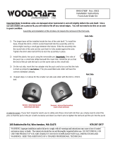
3. Press the crown race onto your new fork. (See Figure #1)
4. Preassemble the fork on the bike with the headset, stem, and
spacers (optional). Refer to your stem manufacturer’s instructions to
determine how much room is needed to clamp the stem.
5. Mark the steerer tube at the top of the stem. The steerer tube will
now need to be cut to the correct length. Disassemble and cut 3mm

The compression adjustment knob is located on the top of the damper-
side fork leg. There are 8 clicks of adjustment. Your fork comes from
the factory in the first, least damped position.
COMPRESSION ADJUSTMENT
As you turn the dial clockwise, you are adding compression
damping or slowing the forks compression stroke. It is an adjustment
that is subtle, and often overlooked, but can make a big dierence
in how your fork performs. Aggressive riders tend to like more
compression damping because it provides a firmer, more supportive
feel. Comfort oriented, less aggressive riders tend to like less
damping in order to maximize small bump sensitivity. Do not confuse
compression damping with spring rate. They are very dierent
adjustments, and while adding compression damping may make the
fork feel “stier”, it is not changing the spring rate.
REBOUND ADJUSTMENT
Adjustments to rebound can be made by turning the red knob on the
bottom of the damper-side fork leg. The total usable range of rebound
adjustment on the Raven is approximately 20 clicks.
Rebound damping is what prevents your suspension fork from
feeling like a pogo stick. It controls the rebound stroke of the fork
after a compression stroke (bump) has occurred. Increasing (turn knob
clockwise) rebound damping slows the rebound stroke of the fork.
Decreasing (turn knob counter clockwise) rebound damping speeds up
the rebound stroke of the fork. Ideally, you want to arrive at a setting
that allows your wheel to track the terrain and not get bounced o line.
S tar F a ngled Nut
S teerer Tube
S teering S t r
F ra m
Hea
em O ptiona l Heads et S pace
Hea ds et Upper R ace
e with
dset C ups
Hea ds et Lower R ace
F ork C rown
FIGURE 1
FIGURE 2
FIGURE 3
(1/8”) below the mark. Consult your dealer or mechanic if you don’t
have the proper tools to cut the steerer tube.
6. The star-fangled nut must now be installed into the steer tube. If you
don’t have the set tool, we recommend dealer installation of this part.
(See Figure #3)
7. Clean and grease all headset bearings and races to prepare them
for assembly. Note: Replace the bearings if there is any sign of wear or
corrosion.
8. Now loosely assemble the headset, stem and handle bars as done in
step four.
9. Install the headset according to the manufacturer’s instructions until
there is no play and the fork turns smoothly.
10. Install your front brake and adjust according to the manufacturer’s
instructions.
11. Install the wheel on the fork. Proper installation of the axle is
communicated in the next section of this manual.
12. Check to see that the brakes are adjusted and properly working.
Make sure that the brake cable does not interfere with any part of the
bike and is secured under the brake hose clamp on the fork brace.
Make sure your brakes are adjusted and functioning properly, and the
brake hose does not interfere with any part of the bike when the fork is
compressed and released.
IMPORTANT BRAKE INFORMATION:
THE RAVEN FORK FEATURES A POST MOUNT FOR 180mm ROTORS.
SHOULD YOU WANT TO USE A LARGER ROTOR, MAKE SURE TO USE
THE APPROPRIATE DISC BRAKE ADAPTOR AS RECOMMENDED BY
YOUR BRAKE MANUFACTURER. FAILURE TO DO SO COULD RESULT IN
SERIOUS INJURY OR DEATH.
IMPORTANT:
WHEN INSTALLING THE WHEEL OR A NEW TIRE, CHECK FOR MINIMUM
CLEARANCE. RELIEVE AIR PRESSURE IN THE AIR SPRING AND
COMPRESS FORK COMPLETELY TO BOTTOM OUT. THERE MUST BE
1/8” OR 3mm OF CLEARANCE BETWEEN THE CROWN AND HIGHEST
POINT ON THE TIRE AT FULL BOTTOM OUT TO ENSURE ADEQUATE
CLEARANCE IN ALL RIDING CONDITIONS.
OPERATING THE BOLT-ON AXLE
1. Seat hub into the dropouts of the fork.
2. Insert axle through the disc brake side dropout, through the hub and
into the captive nut on the non-disc brake side dropout.
3. Using a 6mm hex tool, thread axle into the captive nut and tighten to
12-15 Nm. DO NOT TIGHTEN THE BOLT-ON AXLE
USING THE 8mm HEX FITTING ON THE CAPTIVE NUT.

AIR PRESSURE FILL PROCEDURE
1. Unthread and remove the negative air chamber cap found on the
bottom of the spring leg.
2. Attach a high-pressure, suspension specific pump to the valve and
using the pump’s bleed button, remove all pressure. Remove the pump.
3. Locate the positive air chamber cap at the top of the spring leg.
Unthread and remove the positive air chamber cap and attach a high-
pressure suspension specific pump to the valve.
4. Fill the positive air chamber to the desired pressure. Remove the
pump and re-install the positive air chamber cap.
5. Return to the negative air chamber; attach the pump, fill to the
desired pressure, remove the pump, and re-install the negative air
chamber cap.
AIR SPRING SETUP
The Raven uses MRP’s FulFill™ air spring system with independent
positive and negative chambers. It is critical the you follow the steps
below in order for proper suspension function.
Because the Raven is a high-performance fork and its desired
feel is highly subjective, we recommend experimenting with dierent
air pressure settings in conjunction with air-volume modifications (using
the included Huck Pucks).
In testing, we’ve found that the common usable range for air
pressure is between 48 - 150 PSI. A good starting point for most riders
on our 150 and 160mm forks seems to be a positive pressure (in PSI)
equal to approximately 40-45% of body weight in pounds (lbs.). For
example, a 175 lb. rider should start with 70 PSI in the positive chamber.
Shorter travel forks may require more pressure than this, and longer
(170mm) forks less, but this a good baseline. Most riders like slightly
more pressure in the negative chamber. You may inflate the negative
chamber to as much as 10% or 10 PSI (whichever is greater) more than
the positive chamber.
HUCK PUCK (AIR VOLUME) TUNING
Some Raven models come stock with Huck Pucks installed. The
maximum number of huck pucks your fork can accomodate depends
on chassis (wheelsize) and travel. The installation of Huck Pucks
reduces the volume of the positive air spring and thereby changes the
overall spring curve. With additional Huck Pucks, the biggest change
occurs at the end of the stroke, where it becomes more progressive
(less susceptible to bottom-out).
HUCK PUCK INSTALLATION OR REMOVAL
1. Release all air pressure from the negative air spring by depressing
the Schrader valve core on bottom of the air leg of the fork. Repeat
the same for the positive spring (at the top of the air leg of the fork). To
ensure all air is released from both chambers, cycle the fork 2-3 times
and depress the positive valve core again.
3. Unthread the spring-side top cap from the crown of the fork using a
cassette tool.
4. With the top cap removed, install or remove Huck Pucks. Use up to
a 4mm hex key or something of similar diameter inserted into the side
of the pucks to tighten or loosen the pucks. Tighten any installed pucks
onto the bottom of the top cap snugly so they do not come loose over
time.
5. Re-install the top cap by threading it back into the fork crown and
tighten to 12 Nm.
6. Inflate the air spring as outlined in the previous section. Added Huck
Pucks will require slightly lower air pressure values to preserve the
previous sag level.
27.5” MODELS
170 and 160: 0 installed, 5 max.
150: 0 installed, 6 max.
140: 1 installed, 7 max
27.5+ / 29” MODELS
160: 0 installed, 5 max.
150: 0 installed, 6 max.
140: 1 installed, 7 max.
130: 2 installed, 8 max.
120: 3 installed, 8 max.
If you are unfamilar with lbs. (pounds) the conversion from kg.
(kilograms) is: kg. x 2.2 = lbs.
Here, below, are some examples of baseline settings, including
rebound settings (counted as “clicks from closed”):
/