
FORKS
F 535 ONE
TECHNICAL MANUAL
V2018.09

2
1. GENERAL ..................................................................................................... 3
2. DESCRIPTION .............................................................................................. 6
3. SMALL SERVICE .......................................................................................... 11
4. CONVERTING THE CONTROL ELEMENTS FROM MANUAL TO REMOTE . 21
5. CONVERT THE CONTROL ELEMENTS FROM REMOTE TO MANUAL ........ 27
6. ADDING / REMOVING APT VOLUME SPACERS........................................... 33

F 535 - technical manual
3
1. GENERAL
1.1 VALIDITY
This manual describes the component specied on the front page and the footer. It is valid for the
construction level of the component on the 26.09.18. Deviations are possible and all items are subject to
technical changes.
1.2 SAFETY
The safety instructions are classied as follows:
DANGER
...indicates a hazardous situation that, if not avoided, will result in death or serious injury.
CAUTION
… indicates a hazard with a medium level of risk which, if not avoided, may result in minor or moderate
injury.
NOTE
… indicates a potentially hazardous situation that may result in damage to property.
1.3 TARGET GROUP
This manual is intended for end users and dealers. It offers the possibility for experienced users to carry out
small maintenance works on their own. If there are any doubts concerning the own skills, a DT Swiss service
center should be contacted.
If the work is not carried out properly, any warranty claims expire.
1.4 LAYOUT
The cover page and the footing provide information about the type of product and manual as well as the
version of the manual. On the back you will nd the DT Swiss contact details. A list of all DT Swiss service
centers can be found at www.dtswiss.com.
This manual is intended for being printed as an A5 booklet. Only print this manual if electronic usage is not
possible.

4
1.5 DT SWISS MANUAL CONCEPT
The DT Swiss manuals are split into the following types of manuals:
• User Manual: Information for the end user on how to install and use the component.
• Technical Manual: Detailed information for the end user and the dealer on how to maintain the
component, spare parts and technical data.
1.6 USING THIS MANUAL
The steps described in this manual must be carried out in the order they are shown. If steps are ignored or
executed in a wrong order, the function of the component cannot be guaranteed.
Instructions begin with the table «Preparatory Steps» and end with the table «Closing Steps». The instructions
in these tables must be carried out.
1.7 GENERAL MAINTENANCE INFORMATION
Unless otherwise specied, moving parts, threads, O-rings and seals must be greased before assembly.
CLEANING
For an optimal result of the maintenance works, every component that will be disassembled must be cleaned.
Only use cleaners which do not damage the components. Especially the cleaning of O-rings and sealings
requires mild cleaners. Observe the instructions for use of the respective cleaning agent.
DT Swiss recommends the following cleaning products:
• Motorex Rex
• Motorex Swissclean
• Motorex OPAL 2400, 3000 OPAL, OPAL 5000
Use soap water or similar mild cleaners for external cleaning.
TOOLS
To ensure a damage-free mounting and dismounting of the components, only use the tools which are
mentioned in this manual. Special tools are indicated at the beginning of a chapter in the table "Required
material".
The use of different tools is at the discretion of the user. If components are damaged by the usage of differing
tools, the user is liable.
DT Swiss special tools are precision tools. Damage-free mounting and dismounting of the components can
only be ensured if the tools are working properly and if the conditions of the tools are perfect. Always keep the
tools in their original packaging or adequate devices to save them from damages.

F 535 - technical manual
5
1.8 ENVIRONMENTAL PROTECTION
The statutory regulations shall apply. Whenever possible, waste has to be avoided. Waste, especially carbon,
lubricants, cleaners and any other uids must be disposed in an environmentally compatible manner.
Only print this manual if electronic usage is not possible.
1.9 EXCLUSION OF LIABILITY
The activities listed in this manual may only be carried out by persons with sufcient specialist knowledge.
The user is liable for any damage or consequential damage caused by wrong maintained or wrong installed
components. If you have doubts, please contact your allocated DT Swiss pro level service center.
1.10 WARRANTY (EUROPE)
In addition to the general guarantee required by law, DT Swiss AG based in Biel/Switzerland, provides a
guarantee for 24 months from the date of purchase. DT Swiss AG shall reject any liability for both indirect
damage caused by accidents and consequential damage.
Any contradictory or extended national rights of the purchaser are not affected by this warranty. Place of
performance and jurisdiction is Biel/Switzerland. Swiss law shall apply.
Submit any warranty claims to your retailer or a DT Swiss service center. Any defects recognized by DT Swiss
AG as a warranty claim will be repaired or replaced by a DT Swiss service center.
Warranty and guarantee claims can only be made by the original purchaser with a valid sales receipt.
There shall be no claim under the guarantee for:
• Normal wear and tear caused by use of the components
• Incorrect assembly
• Incorrect or nonexistent maintenance
• Incorrectly completed repairs
• Use of unsuitable products
• Modication of components
• Incorrect use or misuse
• Carelessness
• Leasing, commercial use or use in competitions
• Damage caused by accidents
• Delivery and transport damage
• Modication, defacing or removal of the serial number

6
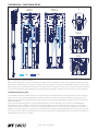
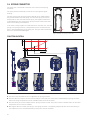
2. DESCRIPTION
The damping unit controls the compression and rebound speed of the fork. During compression and rebound movements of
the suspension fork, oil is pressed through holes with adjustable cross section and through small spring plates (shims) which
allow more oil to pass through as the oil pressure increases (the faster the movement of the suspension fork, the higher the
oil pressure).
The damping unit is a closed system. The damping oil is separated from the air in the fork by a preloaded oating piston. This
prevents the oil from foaming and ensures a constant damping performance even on long, rough downhills.
2.1 COMPRESSION
The damping unit was rethought right from the start in the design of the F 535 suspension fork. A system was realized
that allows different damping characteristics over the stroke of the fork. In the rst third of the travel, the suspension fork
responds extremely sensitively, with a rmer characteristic after the rst third of the travel. This system provides maximum
traction and at the same time high control and feedback on the ground.
The low-speed compression (LSC) can be pre-adjusted in three steps «OPEN», «DRIVE» and «LOCK» for different terrain and
different demands.
OPEN
Full functionality and sensibility of the fork can be attained in the mode «OPEN». This setup is mostly suitable for downhills,
technical and rough uphills and comfortable rides on at trails.
In order to meet the requirements of all riders, the low-speed compression can be set in “OPEN”mode with the setup tool
(Torx T10). The fork is very sensitive and comfortable when the compression damping is fully open (counterclockwise to the
stop). To use the full potential of the fork, we recommend using it with the compression damping fully open regardless of the
rider's weight and the bicycle. The compression damping can be incrementally increased for a less sensitive response.
DRIVE
The «DRIVE» mode sets the fork into a very rm mode. The fork moves, but is very rm. Movements from pedaling are mostly
eliminated. This setting is mostly advantageous for sporty and efcient pedaling on at trails and uphills.
LOCK
The «LOCK» mode blocks the fork in fully extended position. This is mostly suitable for situations where no suspension is
needed (for example riding on the road or connecting trails). The lockout in the «LOCK» mode is hard and dened. A blow-off
valve protects rider and material from unexpected hits.
High speed compression (HSC)
The setup of the high-speed compression leads to a controlled feeling even on hard hits, jumps or steps. The high-speed
compression is pre-set and is not adjustable.

F 535 - technical manual
7
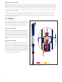
COMPRESSION - FUNCTION IN DETAIL
LSC HSC
LOCK
DRIVE
OPEN 1 OPEN 2
C
gure 1: Compression - function in detail
When the fork compresses, the piston inside the oil chamber is pushed upwards. Some of the oil passes through a one way
valve past the piston (see gure 1) into the lower part of the oil chamber. Thus the volume beneath the piston is smaller than
above, only part of the displaced oil can ow into the space beneath the piston. This excess oil is pushed through the damping
circuit into the upper part of the damping unit. The preloaded oating piston creates a counter pressure to the inowing oil.
Low Speed Compression (LSC)
In the «OPEN» mode the oil ows through the oil channel of the low-speed compression (LSC) and thus over the adjusting
needle, which position can be adjusted with the external compression adjuster (see gure 1/OPEN 1). The position of the
adjusting needle controls the ow resistance of the oil and thus the intensity of damping. The higher the ow resistance, the
higher the damping.
The oil ows through the channel of the low-speed compression into an area where the oil presses a preloaded piston
downwards (see gure 1/OPEN 1). The piston can be pressed down until the oil channel of the incoming oil is closed by a
sliding bushing. From this position, the oil can only ow through the channels of the high speed compression (see gure 1/
OPEN 2). This function gives the suspension fork its characteristic property: The damping responds very sensitively over the
rst third of the travel. After exceeding the rst third of the spring travel, the damping becomes rmer and thus prevents too
rapid and deep immersion in the travel.

8
High speed compression (HSC)
Additionally, the oil ows through the oil channel of the high-speed compression (HSC). Shims are placed at the end of the oil
channel. These shims only open when a dened oil pressure is attained. Oil which cannot ow through the oil channels of the
LSC (because of fast deection of the fork, and thus big displacement of the oil generated by the piston), ows through the oil
channels of the HSC. This ensures separate damping characteristics on small and medium or on fast compression speeds.
In «DRIVE» mode, the oil channel of the «OPEN» mode is closed. The oil ows through a separate oil channel onto a special
shim stack (see gure 1DRIVE).
In mode «LOCK» (see gure 1LOCK), a slider closes the oil channels of the low-speed compression (LSC) and high-speed
compression (HSC). The oil can only ow through the blow-off channel. Shims at the end of the blow-off channel open the
access to the HSC channel at a dened oil pressure. The blow-off itself does not represent a damping function, it protects
rider and material from big hits.
2.2 REBOUND
The preloaded oating piston pushes the oil from the
upper part of the damping unit into the oil chamber when
the fork is released. The oil can ow directly from the
upper unit of the damping unit into the oil chamber.
The rebound damping happens in the damping piston.
Low-speed rebound (LSR)
When the fork rebounds slowly, the oil ows through the
oil channel of the low-speed rebound (LSR). An adjusting
needle, which position can be adjusted with the red
rebound adjuster, controls the owing resistance through
the LSR oil channel. The position of the adjusting needle
controls the ow resistance of the oil and thus the intensity
of damping. The higher the ow resistance, the higher the
damping.
High speed rebound (HSR)
Additionally, the oil ows through the oil channel of the
high-speed rebound (HSR). Shims are placed at the end
of the oil channel. These shims only open when a dened
oil pressure is attained. Oil which cannot ow through the
oil channels of the LSR (because of fast rebound speed of
the fork and thus big displacement of the oil generated by
the piston) ows through the oil channels of the HSR. This
ensures separate damping characteristics on small and
medium or on fast rebound speeds.
LSR HSR
gure 2: Rebound - Function in Detail

F 535 - technical manual
9
2.3 SPRING
The Line Air system consists of a bypass located in the air chamber. The bypass ensures that the pressure inside the negative
air chamber is higher than in the positive air chamber when the fork is fully extended. This reduces the force of the beginning
stroke. The fork responds very smooth and offers more comfort and traction.
FUNCTION IN DETAIL
After inating or changing the air pressure:
When the fork compresses, the piston moves over the bypass
of the air chamber.
When the piston is located on the bypass, the bypass ensures
a pressure equalization of the positive and negative air
chamber (see red arrow).
gure 3: Pressure compensation via the bypass valve
Function during operation:
Due to the pressure equalization, the pressure in the negative
air chamber is higher than in the positive air chamber when
the fork is fully extended. This increased pressure inside the
negative air chamber counteracts to the breakaway torque
and improves the response characteristics drastically.
When the fork is compressed further, only the air inside the
positive air chamber is compressed.
When the fork extends again, a pressure builds up in the
negative air chamber and the cycles starts again.
gure 4: Pressure conditions with unloaded fork

10
2.4 SPRING CONNECTOR
The spring unit is connected to the lower unit of the fork via a spring
connector.
The spring connector basically consists of a coil spring and a guide
bushing.
The steel spring of the spring connector absorbs minor impacts before
they can be transferred to the spring unit. Since the spring unit with its
sliding seals is more inert than a steel spring, the slightest unevenness
is absorbed by the steel spring of the spring connector without the seals'
static friction having to be overcome.
In the event of major impacts or sustained force on the lower unit, the steel
spring in the spring connector is compressed to such an extent that the
force is transmitted directly to the spring unit. The cycle starts anew when
the fork is relieved and loaded again.
gure 5: Close-up spring connector
FUNCTION IN DETAIL
Kraft [N]
Federweg [mm]
50 100 150
450
1750
A
B C D
gure 6: Spring connector- function in detail
AThe fork is fully extended. No force is applied to the spring connector.
BThe fork starts to compress. On the rst millimetres of the travel, the entire force is absorbed by the spring connector
without air being compressed in the air chamber (static friction of the seals).
CThe force acting on the fork compresses the spring connector further. The piston of the air chamber starts to move and
compresses the air in the air chamber.
DAfter approx. 30 mm of travel, the spring in the spring connector is completely compressed. The entire force acting on
the suspension fork is transmitted directly to the piston of the air chamber.

F 535 - technical manual
11
3. SMALL SERVICE
3.1 REQUIRED TOOLS AND MATERIALS
Required tools and materials Specication Quantity Article number
Wiper seal kit Ø35
• 2 x wiper
• 2 x foam ring
• 2x O-ring
1FWKXXXXXXXXX20369S
DT Swiss Lube Fluid 100 ml 4064XXXXXXXX000026
DT Swiss Fork Oil 100 ml 4064XXXXXXXX000024
Wiper seal mounting tool 1FWTXXXXXX10015661S
Reworked 8 mm hex bit 1FXTXXXXXXXX018482S
Mounting tool for spring unit 1FWTXXXXXXXX014126S
Syringe (minimum volume 20 ml) 1-
Tire lever 1-
Degreaser - -
Torque wrench 25 Nm 1-
Plastic hammer 1 -
Shock pump 1-

12
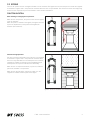
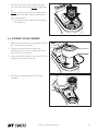
3.2 RELEASING THE AIR
1. Unscrew the xing screw of the cover on the
spring side.
2. Remove the cover. T10 Torx
3. Unscrew the valve cap.
4. Carefully press the back of the valve cap
onto the valve insert and slowly release the
air.
5. Slowly compress the fork two times about
10 mm with the valve insert pressed and
pull it apart again.
→ This balances the positive and negative
air chambers.

F 535 - technical manual
13
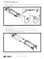
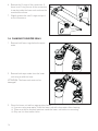
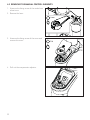
3.3 REMOVING THE LOWER UNIT
1. Make sure the valve cap is removed and the air is completely released (see „3.2 Releasing
The Air“ on page 12).
27,5“ 29“
FXTXXXXXXXX018482S
2. Screw in the screw on the spring side clockwise into the lower unit using the tool
FXTXXXXXXXXXX018482S.
3. Screw in the screw on the damping side clockwise into the lower unit using the tool
FXTXXXXXXXXXX018482S.
→ After the screws have been screwed in, about 20 ml of oil runs out of both dropouts.
Collect the leaking oil using a suitable container.
4. Carefully remove lower unit.
5. Collect the leaking oil using a suitable container.

14
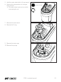
6. Remove the O-rings of the connectors. If
there is no O-ring on one of the connectors,
it may be inside the lower unit and must be
removed from there.
7. Slightly grease the new O-rings and put it
on the connectors.
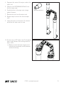
3.4 CHANGING THE WIPER SEALS
1. Remove both foam rings below the wiper
seals.
2. Remove both wiper seals from the lower
unit using a solid tire lever.
ATTENTION: The lower unit must not be
damaged!
3. Clean the lower unit with an appropriate cleaner.
→ If you are using soap water, ush the lower unit with clear water after cleaning.
→ There must be no residual moisture inside the lower unit before re-mounting.
→ Only use lint-free textile cloths.

F 535 - technical manual
15
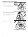
4. Degrease the seats of the wiper seals in the
lower unit.
5. Slide the tool FWTXXXXXX10015661S into
the rst wiper seal.
6. Carefully drive in the wiper seal using a
plastic hammer.
7. Remove the tool from the wiper seal.
8. Repeat steps to mount the second wiper
seal.
9. Leave the lower unit for about 15 minutes
and allow the wiper seals to seat.
FWTXXXXXX10015661S
10. Put two new, in DT Swiss Lube Fluid soaked
foam rings between the bushings and the
wiper seals.
→ Make sure that the foam rings are not
twisted and completely evenly between
seal and bushing.

16
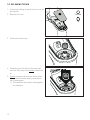
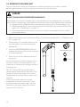
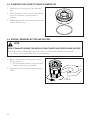
3.5 REMOVING THE SPRING UNIT
As part of the small service we recommend to remove the spring unit in order to remove
introduced lubricating oil from the spring unit and from the left stanchion.
DANGER
RISK OF INJURY FROM PRESSURIZED COMPONENTS!
If the spring unit or the air chamber cap is removed without rst releasing the air, the spring
unit or the air chamber cap is ejected from the stanchion after loosening the screw connection.
• Release the air completely before unscrewing the spring unit or the air chamber cap.
• While deating the air, move the fork several times through the travel and deate the air
again
(see „3. Small service“ on page 11)
.
• Components that may be under pressure must never point towards the face or body
during disassembly.
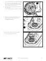
1. Make sure the valve cap is removed and the air is completely released (see „3.2 Releasing The
Air“ on page 12).
2. Clamp the fork in a suitable device so that
the open sides of the stanchions points
downwards.
3. Using the FWTXXXXXXXXXX014126S tool,
unscrew the spring unit from the underside
of the left stanchion.
4. Drain the oil from the stanchion and the
spring unit.
It is not necessary to clean the spring unit or
the inner surface of the left stanchion. The
remaining oil lubricates the sliding surfaces of
the spring unit.
The 130, 140 and 150 mm models have a
volume spacer inside the left stanchion. The
position of the volume spacer must not be
changed and the volume spacer must not be
removed.
If the volume spacer has been moved
accidentally, it must be positioned so that
the distance from the lower edge of the left
stanchion to the lower edge of the volume
spacer is 247 to 252 mm.
FWTXXXXXXXX014126S
27 mm

F 535 - technical manual
17
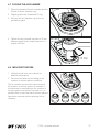
3.6 ASSEMBLING THE SPRING UNIT
1. Make sure that there is still residual oil on the seals of the spring unit. Grease the seals with
a small amount of DT Swiss Fork Oil if necessary.
2. Push the screw connection of the spring
unit as far as possible in the direction of the
piston.
3. Screw in the spring unit from the bottom
using the tool FWTXXXXXXXX014126S and
tighten with a torque of 20 Nm.
Make sure that the screw connection of the
spring unit is pushed as far as possible in
the direction of the piston. FWTXXXXXXXX014126S
20 Nm
27 mm

18
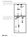
3.7 ASSEMBLING THE LOWER UNIT
1. Before mounting the lower unit, the damping unit should be fully compressed once. This
ensures that the correct amount of damping oil is in the damping unit. A small amount of oil
may drip from the stanchion.
2. Pull out the damping unit completely.
Vertical play in the damping unit is normal.
3. Check, if the O-rings of the connectors are still in place.
4. Slide the SAG O-ring onto the stanchion tube if necessary.
5. Slide the lower unit about 5 cm onto the stanchions.

F 535 - technical manual
19
6. Fix the fork 45° - 70° upright.
7. Fill 20 ml DT Swiss Fork Oil into the spring side of the lower unit.
8. Fill 20 ml DT Swiss Fork Oil into the damping side of the lower unit.
9. Allow the fork to rest in the previously xed position for about 60 seconds to allow the
bushings to be lubricated.
10. Fully slide the lower unit onto the stanchions. Do not compress the piston rods of the spring
and damping unit.
12 Nm
27,5“ 29“
FXTXXXXXXXX018482S
11. Screw in the screw on the damping side counterclockwise into the lower unit using the tool
FXTXXXXXXXXXX018482S and tighten the screw with a torque of 12 Nm.
12. Screw in the screw on the spring side counterclockwise into the lower unit using the tool
FXTXXXXXXXXXX018482S and tighten the screw with a torque of 12 Nm.

20
3.8 INFLATING THE FORK
1. Inate the fork (see user manual for
detailed information).
2. Screw on the valve cap.
3. Put on the cover and tighten the xing
screw handtight (max. 0.2 Nm).
T10 Torx
max. 0.2 Nm
Page is loading ...
Page is loading ...
Page is loading ...
Page is loading ...
Page is loading ...
Page is loading ...
Page is loading ...
Page is loading ...
Page is loading ...
Page is loading ...
Page is loading ...
Page is loading ...
Page is loading ...
Page is loading ...
Page is loading ...
Page is loading ...
Page is loading ...
Page is loading ...
Page is loading ...
-
 1
1
-
 2
2
-
 3
3
-
 4
4
-
 5
5
-
 6
6
-
 7
7
-
 8
8
-
 9
9
-
 10
10
-
 11
11
-
 12
12
-
 13
13
-
 14
14
-
 15
15
-
 16
16
-
 17
17
-
 18
18
-
 19
19
-
 20
20
-
 21
21
-
 22
22
-
 23
23
-
 24
24
-
 25
25
-
 26
26
-
 27
27
-
 28
28
-
 29
29
-
 30
30
-
 31
31
-
 32
32
-
 33
33
-
 34
34
-
 35
35
-
 36
36
-
 37
37
-
 38
38
-
 39
39


Ask a question and I''ll find the answer in the document
Finding information in a document is now easier with AI
Related papers
Other documents
-
Manitou Mara Pro Piggyback Complete Service guide
-
SRAM RockShox RS-1 User manual
-
Cannondale Lefty Oliver Owner's manual
-
-
 ibis Mojo 3 Instruction book
-
White fluid 29 130 User manual
-
-
 HP Velotechnik GrassHopper fx and Operating Instruction And Service Instructions Manual
-
 Eko Brands Bicycle XC0.8 User manual
-
Ohlins 07430-01 Owner's manual


